reinforced concrete beams Subjected to HC Fire
GUERGAH Cherif
1, DIMIA Mohamed Salah
2and GUENFOUD Mohamed
11Laboratory of Civil Engineering and Hydraulics, University of Guelma, Algeria, mail: gcheriff@yahoo.fr 2Department of civil Engineering, Laboratory of Applied Research in Hydraulics LRHYA,University of Batna, Algeria, mail : mohamedsalah.dimia@univ-batna.dz
3Laboratory of Civil Engineering and Hydraulics, University of Guelma, Algeria, mail:gue2905m@yahoo.fr
RÉSUMÉ. Cet article vise à mener une étude numérique concernant la prise en charge du phénomène d'écaillage du béton dans les poutres en béton armé sollicités au feu Hydrocarbure (HC) et son influence sur leur stabilité structurale. La manifestation de ce phénomène peut commencer dès les premières minutes, mettant à nu les armatures les plus près du parement en accélérant la perte de résistante et pouvant conduire à une rupture prématurée de la structure. La prise en compte du risque d'écaillage des bétons dans les différentes règlementations s'articule principalement autour des approches expérimentales, aucun calcul prédictif ne peut être encore réalisé, car la prédiction exacte de ce phénomène reste encore mal connue. Dans ce contexte le logiciel SAFIR est utilisé pour effectuer une analyse numérique du risque d'écaillage par l'élimination progressive de couches de béton d'enrobage à chaque fois que les critères d'apparition de ce phénomène sont remplis. L'étude paramétrique que nous avons menée, a porté sur: La généralisation de l'écaillage le long de l'élément ou non, la prise en compte d'un écaillage qui se manifeste sur une ou plusieurs faces de cet élément et l’influence de différents paramètres tels que la variation des conditions aux limites et la réduction des propriétés mécaniques des matériaux en fonction de l’évolution de la température. Les résultats obtenus montrent l'influence majeure de l'écaillage sur la stabilité mécanique des éléments structuraux en situation d'incendie et cela soit par la réduction du temps de ruine et/ou par la réduction de la contrainte de rupture et du module tangent.
ABSTRACT. The aim of the paper is the realization of a numerical study, in which the spalling phenomenon of concrete in reinforced concrete beams subject to hydrocarbon fire (HC) is considered, and its influence on their structural stability is analyzed. The manifestation of this phenomenon can start during the first few minutes, exposing the reinforcement nearest to the fire, and it subsequently accelerates the loss of resistance, thus causing premature failure of the structure. Taking into account the spalling risk of concrete, various regulations are often based on experimental approaches, and therefore no predictive calculation can yet be realized. The accurate prediction of this phenomenon remains unknown. In the context of this work, the SAFIR code may be used to perform a numerical analysis of the spalling risk, by removing layers of concrete covering when a set of spalling criteria are checked. The parametric study focused on: The generalization of the spalling along the element or not, taking account of spalling which occurs on one or more sides of the element, and the influence of various parameters such as changes in boundary conditions and reduced mechanical properties of materials as a function of changes in temperature. The results obtained show the major influence of spalling on the mechanical stability of structural elements in a fire situation, and that this is by reducing the failure time and/or by reducing the yield strength and tangent modulus.
MOTS-CLÉS: Feu HC, Écaillage, Poutre, Béton armé, Modélisation, SAFIR.
1. Introduction
In the event of fire, structures are exposed to high temperatures (up to 1200 °C), causing significant damage, which inevitably leads to deterioration of the surface of the concrete by spalling. The manifestation of this phenomenon was first observed long ago but it is still not well understood in the calculation (Kodur, 2005). This is due to the complexity of the phenomenon. According to several authors (Dwaikat and Kodur, 2009; Akhtaruzzaman and Sullivan, 1970; Sanjayan and Stocks, 1993), spalling can be affected by the following factors: the initial strength of the concrete, moisture content, density, the intensity of the fire, the side frame, loading conditions, the type of aggregate, heating rate, the dimensions and shape of the samples. The coupling of these factors can lead to several failure patterns of concrete near the face exposed to the fire.
Moreover, some authors believe that the main causes of the occurrence of this phenomenon are: the low permeability of the concrete, and migration of water vapour into the concrete at elevated temperatures (Kodur and Phan, 2007; Phan, 1996). This study focused on the analysis of the failure risk by spalling of a reinforced concrete beam exposed to fire (HC). The study includes two major components, namely:
Determination of temperature fields in every point of the beam, which is done by solving the transient equations of heat transfer using the finite element method.
Calculations of the fire resistance with and without consideration of the concrete spalling phenomenon. 2. Process of spalling
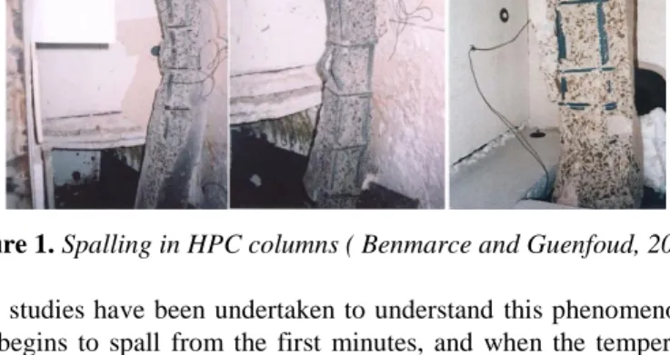
When concrete is subjected to high temperatures, two phenomena can lead to the loss of material: progressive spalling and explosive spalling. From a regulatory point of view, only the explosive spalling term is used (Eurocode 2 2005; Eurocode 4 2005). The explosive spalling is characterized by violent burst-out of concrete pieces characterized by a sudden release of energy (Zeiml et al., 2008). This phenomenon may occur during the first 30 minutes of fire. It is characterized by large or small pieces of concrete being violently expelled from the surface, accompanied by a loud noise (Khoury and Majorana, 2003). The explosive spalling of concrete has been observed under laboratory ( Benmarce and Guenfoud, 2005), (Fig. 1).and real fire conditions (Kodur and Dwaikat, 2010).
Figure 1. Spalling in HPC columns ( Benmarce and Guenfoud, 2005).
Numerous experimental studies have been undertaken to understand this phenomenon. According to Tuyen Phan (2012), the concrete begins to spall from the first minutes, and when the temperature in the concrete is around 150°C. Khoury and Anderberg (2000) concluded that spalling starts within 7 to 20 minutes, when the surface temperature reaches values between 150 and 300 °C. According to Gaweska (2004), the phenomenon may occur at temperatures between 190 and 260 °C. Haniche (2011) and Fletcher et al. (2007) consider that the spalling phenomenon arises at temperatures between 200 and 350 °C. In other works, it was noted at higher temperatures of the order of 250 – 400 °C (DeMorais et al., 2006) and 375 – 425°C (Akhtarnrzaman and Sullivan, 1970; Denny et al., 2009). Noumowé (1995) refers to values between 300 and 350 °C. For high performance concrete (HPC), explosive spalling was observed in the temperature range between 300 and 650 °C (Toumi, 2013). The rate of temperature increase can be considered as a dominant contributing factor that favours the spalling of concrete. According to Faris et al. (2004), a rate of 5 °C/min may be considered sufficient to cause the spalling of concrete.
3. Research context
In order to understand the influence of the spalling risk, we have undertaken a numerical modelling of the spalling of a reinforced concrete beam for various boundary conditions: simply supported beam (SSB), propped
cantilever beam (PCB) and fixed-fixed beam (FFB). The beam is subjected to the action of the hydrocarbon fire curve (HC) (EC1, 2003). In this context, two situations have been targeted: in the first, the beam is supposed to spall on three sides. In the second situation, it is considered that only the lower face of the beam is affected by spalling. We assume that the temperature distribution is uniform over the entire length of the beam, and take account of a global spalling which also occurs in a regular manner along this beam. For this purpose, the SAFIR software (Franssen, 2005) is used, removing a layer of concrete cover (5 mm) whenever the temperature of the exposed surface reaches 400 °C (this temperature seems to be quite sufficient to cause the spalling of concrete) (Deeny et al., 2009; Tuyen Phan, 2012; Jeremy, 2007), then this process has to be continued up to the total disappearance of the concrete cover. Note that the thickness of the layers removed will be a function of the element thickness used in the finite element analysis. The beam is 600 cm long, 30 cm wide and 60 cm high. The following tables present the mechanical characteristics of the materials used. Note that the SAFIR software takes into account a transient creep strain within the constitutive relationships for concrete at high temperatures (Gernay and Franssen, 2012). However, in the EC2 2005 uniaxial concrete material model, transient creep is included implicitly. But the results are very close using the model that takes into account the implicit transient creep .
Table 1. Mechanical characteristics of concrete and steel
4. Thermal Analysis
4.1. Fire models
For this modeling, we assumed that the beam is subjected to the action of the hydrocarbon fire curve (HC). This curve has a very rapid rise in temperature, reaching a temperature of 900 °C in the first 5 minutes, and held at 1100 °C. According to EC1 2003, the temperature–time curve of the hydrocarbon fire is given by:
[ 1 ]
where: θg is the gas temperature in the fire compartment (°C), t is the time (min).
4.2. Thermal analysis results
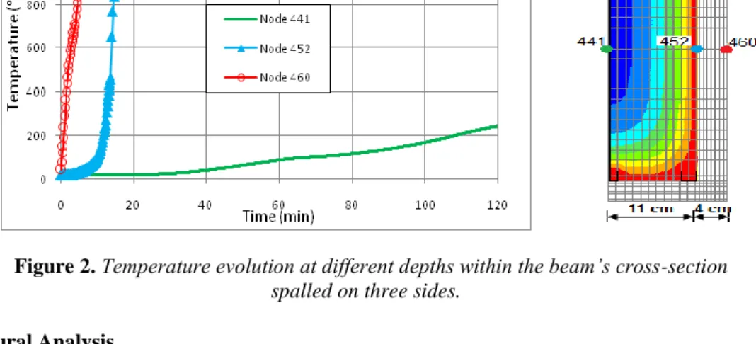
In (Fig. 2) below, we present the temperature evolution inside the cross-section of the spall beam. The temperatures are recorded at different depths of the beam’s cross-section. For this purpose, three points have been targeted and their representative curves are shown below:
The choice of these points is:
Node 460 on the surface of the section, Node 452 at the spalling face,
Node 441 in the centre of the section.
After 15 minutes, node 452 reaches a temperature of 1000 °C while core node 441 reaches only 245 °C after two hours of hydrocarbon fire HC exposure. That is, for a thickness of 15 cm (node 441 - node 460), the temperature difference is the order of 850 °C. In addition, the detachment of the concrete cover accelerates the heat transfer and produces a considerable increase in the temperature. This is explained by the concordance that we clearly observed between the two curves (node 452 and node 460).
Similarly, the temperature evolution of the same nodes for a non-spalled beam was calculated. This time, node 452 has a slow rise in temperature compared to that recorded for the spalled section. This evolution is concretized by the slight slope with the progression of time, with a heating rate of about 5 °C /min. On the other hand, node 441, which represents the position of the section centre, only reaches a temperature of 106 °C after 120 minutes of fire exposure. Accordingly, the concrete, which transmits heat flow only faintly, will have its centre temperature much lower than the external temperature.
Property of concrete (C40/50) Property of steel (fe,a 500) Compressive strength fc28 40 MPa Modulus of Elasticity Ea 210 GPa
Tensile strength ft28 0.0 Tensile strength fe 500 MPa
Poisson's ratio 0.2 Poisson's ratio 0.3
Type of aggregates Siliceous Reinforcement bare 5HA20
Water content 4 %
Cover 4 cm
Figure 2. Temperature evolution at different depths within the beam’s cross-section
spalled on three sides.
5. Structural Analysis
In this study, the beam is longitudinally discretized by Bernoulli beam elements. The transversal cross-sections of the beam elements are divided into fibers corresponding to those defined in the thermal analysis. The beam is subjected to a uniform distributed load of 40 kN/m and is discretized in 21 nodes and 10 elements, as shown in (fig 3).
Figure 3. Schematic of the considered beam.
Despite the high thermal conductivity of the steel, allowing it to absorb heat much more rapidly than other materials, we see from (Fig. 4) that it loses its initial strength after 15 min of exposure to HC fire, and when the cover layer has completely disappeared (red curve spalled section). Therefore, the concrete cover of the non-spalled section has a retarding effect on the decrease of the thermal conductivity of steel, giving it better resistance (blue curve). This shows that the modulus of elasticity is the most sensitive to elevated temperature when it is exposed directly to the fire source, followed by flexural strength and compressive strength.
Figure 4. Reduction of the steel elasticity modulus versus time.
Using the exposure to the HC fire curve, the behaviour of the same beams spalled on three sides was compared to those spalled on the one side. We present below the results of structural analysis for different types of beams.
5.1. Beam spalled on three sides
5.1.1. Simply supported beam (with pin-roller supports)
In Fig 5 the transverse displacements at mid-span of the beam is presented, in the case of a global spalling that occurs along the beam (Fig. 5a) and a local spalling that appears in the middle, i.e. at the location of the maximum positive bending moment (elements 5 and 6 in Fig. 5b).
(b)
(a) global spalling (b) local spalling
Figure 5. Bending moment diagram with spalled area
In Fig. 6, the mid-span deflections of the beams with the two different types of spalling are plotted, showing the comparison between the local and global spalling. When the simply supported beam is exposed to fire, it will expand outwards and gradually deflect downwards. The shape of deflection is linear until 14 minutes, then a plastic hinge starts to form in the mid-span and the deflection increases rapidly afterwards. For global spalling, this deflection is about 23.40 cm with a failure time of 15 minutes. In the case of local spalling, this deflection is of the order of 17.80 cm, corresponding to a failure time of 15 minutes. However, the non-spalled beam has a very big resistance time which exceeds 99 minutes, but it undergoes significant deflection of 29.40 cm (see Table 2).
According to this simulation, it is clear that the results are almost identical for both spalling types, which seems logical, because in a statically determinate system, the formation of one plastic hinge is sufficient to cause the collapse of the structure.
Figure 6. Transverse displacements at mid-span of beams.
5.1.2. Propped Cantilever Beam with fix-roller supports (PCB)
Fig. 7 illustrates the transverse displacements of node 13. Note that the maximum displacement for local spalling is about 22.00 cm, corresponding to a failure time of 17 min, whereas the global spalling causes the failure of the beam in 16 min with a maximum displacement of 18.00 cm. In view of the results obtained, we can see a relative evolution of the fire resistance of the beam (2 min). This is mainly due to the change in the support system. (Adding an embedment changed the failure mechanism).
5.1.3. Fixed-fixed beam
For this case, we have considered a local spalling assumed to appear at mid-span of the beam. The results of the transverse displacements of this simulation are shown in Fig. 8. The differential temperature caused a change in the bending moments and thermal expansion caused development of a compressive axial force.
When the applied bending moment exceeds the residual strength of the beam, a plastic hinge will develop and failure will occur.
We recorded a failure time of 181 min for local spalling, corresponding to a displacement of 0.9 cm, as against the global spalling which caused a displacement of 3.90 cm for a failure time of 129 min. According to Linus (2004), this best performance in fires is due to moment redistribution which allows the loads to be resisted by alternative means after the first plastic hinge forms. This shows the considerable influence of the degree of embedment on the mechanical behaviour of structures under the effect of thermal actions. The results of this simulation are summarized in table 2.
Figure 8. Mid-span deflection of beam.
Table 2. Transverse displacement as a function of failure time for different types of beam.
Scenario Simply supported
beam (SSB)
Propped cantilever beam (PCB)
Fixed-fixed beam (FFB)
Local spalling Displacement (cm) 17.80 22.11 0.90
Failure time (min) 15.50 17.75 181.00
Global spalling Displacement (cm) 23.40 18.30 03.90
Failure time (min) 15.50 16.83 129.0
No spalling Displacement (cm) 29.40 29.80 5.10
Failure time (min) 99.17 152.50 302.00
5.2. Beam spalled on one side
Similarly, we present below the results of the transverse displacements and the failure time corresponding to each scenario and according to different boundary conditions:
The results of this simulation are summarized in table. Fig. 9 shows the bending moment evolution at the mid-span in case of fixed-fixed beam.
-300 -250 -200 -150 -100 -50 0 50 0 40 80 120 160 200 240 280 320 M m o n t (k N .m ) Time (min) Local Spalling Global Spalling No Spalling Table 3. Comparison of failure times (minutes) for various conditions.
Scenario Simply supported
beam (SSB)
Propped cantilever beam (PCB)
Fixed-fixed beam (FFB)
Local spalling Displacement (cm) 09.90 16.50 04.90
Failure time (min) 17.50 20.33 287.50
Global spalling Displacement (cm) 17.20 23.30 05.10
Failure time (min) 17.50 20.08 254.08
No spalling Displacement (cm) 29.40 29.80 05.10
Failure time (min) 99.17 152.50 302.00
Figure 9. Mid-span moment of fixed-fixed beams (FFB).
During the fire, and when the temperature is increased, the moment resisting supports will steadily increase, which can lead the positive moment at span to change its sign. The value of the bending moment at mid-span is about 31.72 kN.m for global spalling and in the order of 16.57 kN.m for local spalling. However, this value reached 23.09 kN.m for the non-spalled beam. It is clear that the fully restrained supports enhance significantly the resistance of structures against spalling. The results above for the beam with spalling on one side reaffirm the crucial role of the support conditions on the structure’s behaviour in a fire situation.
6. Conclusion
For this purpose two situations were analyzed:
In a first situation, we chose the most unfavorable case; i.e. we assumed that spalling occurs along the beam and on the three sides that are heated, in the second situation, a local spalling is examines, which is supposed to appear at the location where there is the maximum bending moment. The following major conclusions can be drawn from the study:
The total disappearance of the concrete cover was recorded at a time of 13 minutes while the rupture occurred at 15 minutes, in other words, immediately after the detachment of the final layer of concrete covering.
Spalling accelerates the formation of plastic hinges, because the resistant cross-section is weakened by the detachment of the concrete covering.
For the embedded elements, and in the case where spalling is considered to occur only on one side, the mechanical behaviour of the beam is only slightly affected.
It is interesting to note that the failure mechanism of the three types of beam with various boundary conditions is the same as for static calculation. Therefore the failure time is considerably affected by spalling. In this study, the rotationally restrained beam at the supports reduces the maximum transverse displacement significantly when exposed to a fire. This confirms the results obtained in other work (Linus et al., 2003; Bernhart, 2004).
7. Bibliography
[KOD 05] Kodur, V.R., «Guidelines for fire resistance design of high strength concrete columns», J Fire Prot Eng, vol. 15, n° 2, 2005, p. 93-106.
[DWA 09] Dwaikat, M.B., Kodur, V.K.R.., «Hydrothermal model for predicting fire-induced spalling in concrete structural systems M.B », Fire Safety Journal vol44, (2009), p.425–434.
[AKH 70] Akhtaruzzaman, A. A. and Sullivan, P. J. E., « Explosive Spalling of Concrete exposed to high temperature », Imperial college of Science and technology, Concrete Structures and Technology, Research report CSTR 1970/2, London.
[SAN 93] Sanjayan, G. and Stocks, L.J., « Spalling of High Strength Silica Fume Concrete in fire », ACI Materials Journal, vol. 90 n° 2, (1993), p.170-173.
[KOD 07] Kodur, V.K.R. and Phan, L.T., «Critical factors governing the fire performance of high strength concrete systems», Fire Safety Journal vol 42, 2007, p.482–488.
[PHA 96] Phan, L.T. «Fire performance of high-strength concrete». A report of the state-ofthe-art. National Institute of Standards and Technology, Gaithersburg, MD, 1996, p 105.
[EN 92] Eurocode 2. (2004), EN 1992-1-2. « Design of Concrete Structures – Part 1-2: General Rules – Structural Fire Design ». CEN – European Committee for Standardization, Brussels.
[EN 94], Eurocode 4. (2004), EN 1994-1-2. « Design of Composite Steel and Concrete Structures- Part 1-2: General Rules-Structural Fire Design ». CEN - European Committee for Standardization, Brussels.
[ZEI 08] Zeiml Matthias, Lackner Roman, Herbert A. Mang., « Experimental insight into spalling behavior of concrete tunnel linings under fire loading »., Acta Geotechnica, vol.3 n° 4, 2008, p. 295-308
[KHO 03] Khoury, G. and Majorana, C., « Effect of heat on concrete ». International Centre for Mechanical Sciences, Udine, Italy. 2003
[KOD 10] Kodur, V. K. R. and Dwaikat, M. B., « Fire Induced Spalling in High Strength Concrete Beams”, Fire Technology, vol46, 2010, p. 251–274.
[BEN 05] Benmarce, A. and Guenfoud, M. (2005), « Behaviour of Axially Restrained High Strength Concrete Columns under Fire », Construction and Building Materials, vol. 57, n°5, 2005, p. 283-287.
[MIN 12] Minh Tuyen PHAN., « Modélisation explicite de l’écaillage sous incendie du béton. Approche thermo-hydro-mécanique avec des conditions aux limites évolutives dimensions », Thèse de Doctorat 2012. Université paris-est, France.
[KHO 00 ] Khoury, G.A. and Anderberg, Y. (), « Concrete spalling », Review Fire safety design, 2000.
[IZA 04] Izabela Gaweska Hager., « Thermal behavior of high performance concretes at high temperature - evolution of mechanical properties », Thèse de doctorat, 2004, Ecole Nationale des Ponts et Chaussées et l’Ecole Polytechnique de Cracovie.
[RAC 11] Rachid HANICHE., « Contribution à l’étude des bétons portés en température/Evolution des propriétés de transfert/Étude de l’éclatement ». 2011, Institut National des Sciences Appliquées de Lyon.
[FLE 07] Fletcher, I.A., Welch, S., Torero, J.L., Carvel, R.O. and Usmani, A. (2007), « The Behaviour of Concrete structures in fire », Journal of Thermal Science, vol.11, n°2,2007, p. 37-52.
[DEM 06] DeMorais, M. V. G., Noumowé, A., Kanema, M., Gallias, J.-L. et Cabrillac, R. (2006). « Transferts thermo-hydriques dans un élément en béton exposé à une température élevée: Approches numérique et expérimentale », 24ème Rencontres Universitaires de Génie Civil (AUGC06), Grande Motte, France, p.1-10.
[NOU 95] Noumowé, A., « Effet de hautes températures (20-6000 °C) sur le béton. Cas particulier du béton à hautes performances », Thèse de Doctorat, 1995, Génie civil, Institut National des Sciences Appliquées, Lyon.
[TOU 13] Toumi Belkacem., « Etude de l'influence des hautes températures sur le comportement du béton », Thèse de doctorat, 2013, Université mentouri Constantine, Algérie.
[FAR 04 ] Faris, A., Nadjai, A.; Silcock, G. and Abu-Tair, A., « Outcomes of a Major Research on Fire Resistance of Concrete Columns », Fire Safety Journal vol.39, 2004, p.433–445.
[EC1 91] Eurocode 1. EN 1991-1-2. « Actions on structures - Part 1-2: General actions - Actions on structures exposed to fire », 2003, CEN, Brussels.
[FRA 05] Franssen J-M., « SAFIR, A Thermal/Structural Program Modeling Structures under Fire », Engineering Journal, A.I.S.C., vol. 42, n°3, 2005, p.143-158.
[JER 07] Jeremy J. Chang., « computer Simulation Of Hollowcore Concrete Flooring Systems Exposed To Fire », thesis doctorate, 2007, University of Canterbury, New Zealand.
[EC3 05] EC3, Eurocode 3. (2005), EN 1993-1-2, « Design of steel structures - Part 1-2: General rules - Structural fire design », 2005, CEN, Brussels.
[GER 12] Gernay Thomas, and Franssen, J.M. (2012), « A formulation of the Eurocode 2 concrete model at elevated temperature that includes an explicit term for transient creep », Fire safety journal vol.51, 2012, p.1-9.
[LIN 03] Linus C. S. Lim., « Membrane Action In Fire Exposed Concrete Floor Systems », Doctoral thesis of Philosophy, 2003, University of Canterbury Christchurch, New Zealand.