DEVELOP AND TEST AN ICCS FOR LARGE SCALE MHD MAGNETS QUARTERLY PROGRESS REPORT
Period from October 1, 1984 to December 31. 1984
Hatch, A. M.; Marston, P. G.; Tarrh, J. M.; Becker, H.; Dawson, A. M.; Minervini, J. V.
March, 1985
Plasma Fusion Center
Massachusetts Institute of Technology Cambridge, Massachusetts 02139 USA
This work was supported by the U. S. Department of Energy, Pittsburgh Energy Technology Center, Pittsburgh, PA 15236 under Contract No. DE-AC22-84PC70512. Reproduction, translation, publication, use and disposal, in whole or part, by or for the United States Government is permitted.
NOTICE
This report was prepared as an account of work sponsored by an agency of the United States Government. Neither the United States Government nor any agency thereof, nor any of their employees, makes any warranty, express or implied, or assumes any legal liability or responsibility for the accuracy, completeness, or usefulness of any information, apparatus, product, or process disclosed, or represents that its use would not infringe privately owned rights. Reference herein to any specific commercial product, process, or service by trade name, trademark, manufacturer, or otherwise, does not necessarily constitute or imply its endorsement, recommendation, or favoring by the United States Government or any agency thereof. The views and opinions of authors expressed herein do not necessarily state or reflect those of the United States Government or any agency thereof.
Page No.
1.0 Introduction. . . . . 1
2.0 Approach (Task I) . . . . 1
3.0 Work Accomplished . . . . 2
3.1 Review of Past Magnet Designs . . . . 2
3.2 Magnet Requirements Obtained from APT Contractors . . . . 2
3.3 Retrofit Size Magnet Pre-Conceptual Design. 2 3.4 Conductor for Retrofit Size Magnet. . . . . 3
3.5 Supporting Analysis . . . . 3
3.5.1 Adiabatic Heating of Conductor. . . 4
3.5.2 Stability Margin and Other Conductor Characteristics . . . . 4
3.5.3 Electromagnetic Analysis. . . . . . 5
3.5.4 Structural Design Basis . . . . 5
4.0 Future Activities . . . . 6
5.0 References. . . . . 7
Tables and Figures
Page No. Review of MHD Magnet Systems Design Data. . . .
Requirements (APT Contractors). . . . . Design Parameters . . . . Design Characteristics. . . . . Conductor Characteristics . . . . 8 9 . . 10 . . 11 . . 12 Figure Figure Figure Figure Figure Figure 1. 2. 3. 4. 5. 6. Figure 7. Figure 8. Figure 9. Figure 10. Figure 11. Figure 12. Figure 13. Figure 14. Figure 15. Figure 16. Figure 17.
Retrofit MHD Magnet Cold Mass Assembly. . . . . Retrofit MHD Magnet Assembly, Elevation . . . . Retrofit MHD Magnet Assembly, Plan View . . . . Retrofit MHD Magnet Assembly. Section at Inlet. . . Retrofit MHD Magnet Assembly, Section at Exit . . . Curves of Temperature Rise in Conductor vs Current Density in Copper, Magnetic Field = 0 T . . . . Curves of Temperature Rise in Conductor vs Current Density in Copper, Initial Magnetic Field = 6 T Diagram Winding of Retrofit MHD Magnet
Pre-Conceptual Design . . . . Curve of On-Axis Field vs Distance Along Axis . . . Field vs Transverse Distance in Magnet Bore
Cross Section Near Channel Inlet. . . . . Field vs Transverse Distance in Magnet Bore
Cross Section Region of Peak On-Axis Field. . . . . Field vs Transverse Distance in Magnet Bore
Cross Section Near Channel Exit . . . . . ... Fringe Field vs Distance from Magnet Center
-Direction of Magnetic Field . . . . Fringe Field vs Distance from Magnet Center Along Axis (X-direction) and Perpendicular to Axis
(Y-direction) and (Z-direction) . . . . Typical Simplified Computer Model of Coils for Determining Fields and Forces . . . . Typical Computer Model of Coils for Determining Fields and Forces . . . .
Typical Simplified Coil Model, Showing Force
Vectors on Each Straight Current Element. . . . . .
-ii-Table Table Table Table Table IV IIIII
IV
V
13 14 1516
17 18 19 20 21 22 23 24 25 26 27 28 29This is the second Quarterly Progress Report covering work done on Tasks I and II of the full-scale conductor development program being conducted by MIT for the Pittsburgh Energy Technology Center (PETC) under Contract DE-AC22-84PC70512. This report covers the period October 1, 1984 to December 31. 1984.
The program consists of the following four tasks: I. Design Requirements Definition
II. Analysis III. Experiment IV. Full Scale Test
The objective of Task I is to establish the design requirements definition for full-scale conductors for use in early commercial MHD magnets. Since
the focus of MHD power train development is now on relatively small systems such as may be used in retrofit applications, the Task I work concerns conductors suitable for systems of that size and type.
Emphasis during the three-year program (Tasks I through IV) will be on the development of the internally cooled cabled superconductor (ICCS) concept for the MHD application. This conceit, which has been under investigation at MIT for a number of years'' , offers great promise in resolving the issues of constructibility and long-term durability for commercial MHD magnets.
2.0 Approach (Task I)
In order to establish a conductor design requirements definition, it is necessary to know the requirements which the MHD system imposes on the magnet and also to know the design characteristics of the magnet that will
be needed to meet those requirements.
Requirements which retrofit-type MHD systems impose on magnets are being determined based on information obtained from PETC, from contractors working on Advanced Power Train studies and from others in the MHD community. This information is supplemented with information on magnet requirements obtained from earlier studies.
Since the scope of the Advanced Power Train studies does not include magnet design. pre-conceptual design work necessary to establish magnet
characteristics is being done by MIT. The first phase of this effort thus provides double service; magnet design data to the APT contractors and conductor design requirements definition for conductor development.
including
Functional requirements System interfaces
Design criteria
-2-3.0 Work Accomplished
To briefly summarize the work accomplished, a review of past magnet designs was made to provide design data as a starting point. Preliminary design requirements were obtained from the APT contractors, and pre-conceptual design work was started on retrofit size MHD magnets. Supporting analyses were initiated in the areas of conductor heating, stability margin, electromagnetics, and structures engineering. The work, which is described in more detail below, was accomplished during the period from October 1, 1984 through December 31, 1984.
3.1 Review of Past Magnet Designs
A brief review of past MHD systems and superconducting magnet designs in the small commercial 3' 7 and retrofit size range was made.
The designs listed in Table I were included. Note that channel powers for these systems are in the range of 29 MWe to 88 MWe, peak on-axis fields are 4 to 6 T, and stored magnetic energies are 700 to 2900 MJ.
Winding and conductor design data, available on some of the designs, indicate design currents in the range of 20 to 25 kA and winding average current densities in the range of 1.4 x 10⁷ to 1.7 x 10⁷ A/cm2 . Only the 35 MWe Retrofit System magnet is based on ICCS; others use designs based on bath-cooled cable or built up conductors. All designs use copper-stabilized NbTi superconductor.
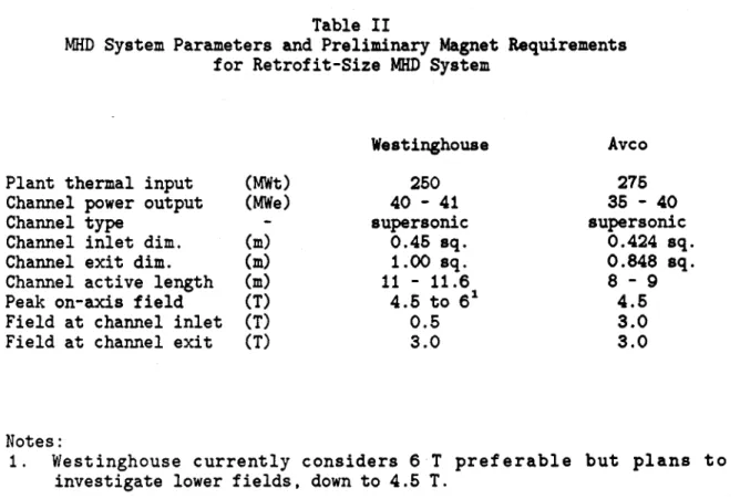
3.2 Magnet Requirements Obtained from APT Contractors
Preliminary magnet requirements for retrofit-size MHD systems, listed on Table II, were obtained from Advanced Power Train (APT) personnel at Avco Everett Research Laboratory Inc. (Avco) and Westinghouse Electric Corporation (Westinghouse). Magnet warm bore size requirements are not included in the table because neither contractor was yet in a position to establish the channel wall thickness and space required for cooling water pipes and electrical power wiring. Avco pointed out that the warm bore size required would depend on whether the magnet was a split, roll-apart design or a one-piece design. Power connections on Avco channels will be brought out from multiple points along the channel and therefore Avco recommended that a liberal amount of space be provided for wiring in the bore of the magnet for a "first-unit" MHD system, to allow for modifications during service.
3.3 Retrofit Magnet Pre-Conceptual Design
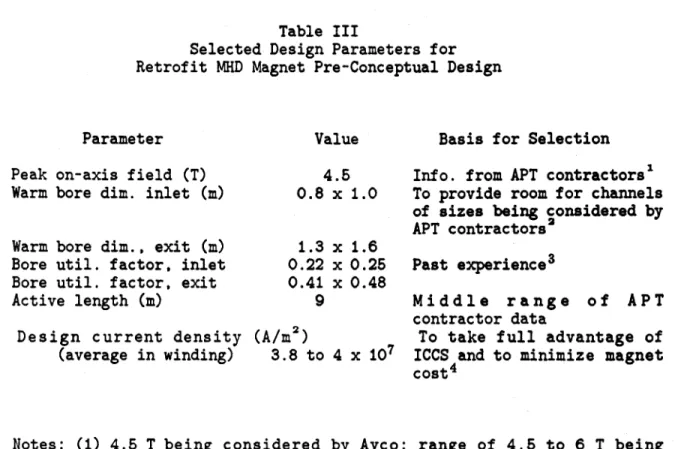
Work was started on the pre-conceptual design of a retrofit MHD magnet to serve as a basis for developing conductor design requirements. The design parameters selected are listed in Table III, together with reasons for selection.
The following design features, particularly advantageous for MHD magnets, were incorporated in the pre-conceptual design:
A rectangular saddle coil configuration which allows the warm bore to be rectangular in shape (instead of square or round) providing
for more effective use of the high-field volume. (See References 4 and 5) .
An end turn configuration (60 degree slope of side and bore) which provides for maximum access to the flow train at both ends of the magnet by allowing the cryostat end surfaces to slope inward toward the bore.
A structural design aimed at minimizing on-site welding during magnet assembly and at maximizing inspectability.
A winding made of internally cooled conductor (ICCS) instead of bath-cooled conductor, with advantages of the ICCS winding including relatively high stability margin, greater winding compactness achieved because separate substructure is eliminated, and superior electrical insulation. The more compact winding, with resulting higher average current density contributes to low overall magnet system cost as discussed in Reference 8.
Provision is made for a guard vacuum enclosure around the winding so that a small leak in the ICCS, should it develop during service, would not degrade the main cryostat vacuum.
Preliminary drawings and design calculations were made for the pre-conceptual design magnet during the reporting period. Drawings included those shown in Figures 1 through 5 as listed below:
Title Figure No.
Cold Mass Assembly 1
Assembly, Elevation 2
Assembly, Plan View 3
Assembly, Section at Inlet 4 Assembly, Section at Exit 5
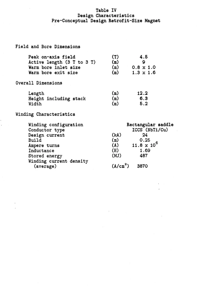
Design characteristics of the pre-conceptual design magnet are listed in Table IV.
The drawings and design data presented here are preliminary and incomplete. The pre-conceptual design will continue during the next reporting period, with supporting analyses to confirm the design concepts.
3.4 Conductor for Retrofit Size Magnet
The conductor used in the retrofit MHD magnet pre-conceptual design described in Section 3.3 has characteristics as listed in Table V.
3.5 Supporting Analysis
Analysis in support of the pre-conceptual design magnet and conductor were started during the report period. Work was accomplished in the following areas.
-4-3.5.1 Adiabatic Heating of Conductor
Safety features in a large magnet system must include provisions to prevent over heating of the conductor in the event that a portion of the winding inadvertently becomes resistive (quenches) due to inadequate cooling or another cause.
It is expected that the protection arrangements in the retrofit MHD magnet system will include a quench detection system and an emergency discharge resistor into which the energy stored in the charged magnet can be dumped rapidly in the event that a quench is detected. Such a system is described in Reference 8. During an emergency discharge, the conductor in the region where the quench started will be subjected to resistive heating during the entire duration of the discharge.
To assure the safety and integrity of the magnet system, the design of the conductor, the winding, and the emergency discharge system must be integrated so that conductor temperature will not exceed safe levels during a worst-case emergency discharge, with the assumption that no cooling is supplied to the conductor during the event.
An analysis of adiabatic heating of the conductor was performed to determine the relationship of conductor (adiabatic) temperature rise to design current density in the copper current path and time constant for emergency discharge, assuming exponential current decay. Information contained in Reference 9 was used as a guide. The results of the analysis are shown in Figs. 6 and 7, which contain curves of conductor temperature rise vs. design current density in copper for various discharge time constants.
An example of the use of the curves in conductor and system design is given below:
Design current in conductor 24 kA
Magnet inductance 1.7 H
Discharge resistor resistance 0.17 ohm Discharge time constant 10 s Discharge initial voltage 4080 V Current density in copper, initial 14.5 kA/cm2 Est. field at conductor, initial 6 T
Final temperature of conductor 220 K (from curves, Fig. 7)
If a discharge initial voltage lower than 4080 V is desired, the discharge resistance can be lowered. This will increase the time constant, with a resulting increase in final conductor temperature. In a similar manner trade-offs can be made among other parameters, such as current density in copper, design current, etc.
3.5.2 Stability Margin and Other Conductor Characteristics
Calculations were made to determine the characteristics of an ICCS conductor using niobium titanium/copper (NbTi/Cu) designed for the following requirements;
Conductor dimensions, outside Sheath Thickness Number of strands Strand dimensions Void fraction Maximum field Design current Critical current Coolant (He) pressure Coolant temperature Max. length of conductor between vents (dbl. pancake) Magnet stored energy
2.08 x 2.08 cm 0.165 cm 486 0.717 mm 0.32 6 T 20 kA 26.7 kA 2.5 atm 4.5 K
600 m
321 MJ The results of the calculations are listed below:Stability margin:
Based on change in enthalpy and constant density
Based on above plus joule heating (more realistic) Maximum quench pressure
Maximum temperature, all stored energy into conductor
Maximum pressure, all stored energy into conductor Copper-to-superconductor ratio 158 mJ/cm3 85 mJ/cm3
13,500 psi
(917 atm) 105 K 6,452 psi (439 atm) 8.6This analytical work was performed on a conductor designed for an early version of the retrofit magnet conceptual design. This work will be repeated as the design concepts evolve.
3.5.3 Electromagnetic Analysis
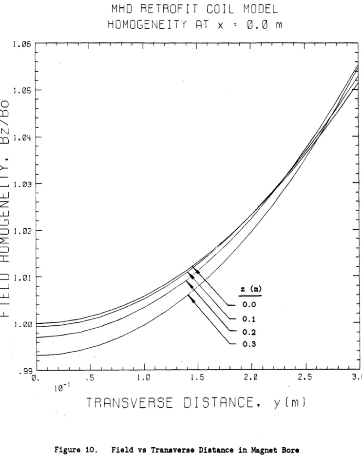
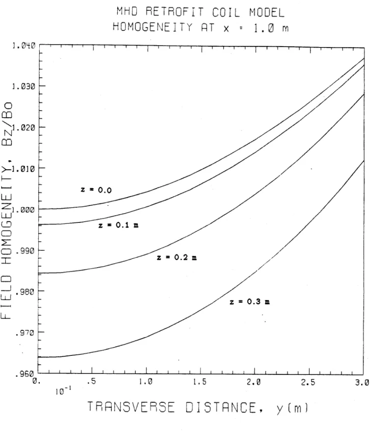
The winding of the retrofit magnet pre-conceptual design as shown in Fig. 8 was analyzed by computer to determine fields 6and forces. On this basis, it was determined that a total of 11.8 x 10 ampere turns were required to produce the desired peak on-axis field of 4.5 T.
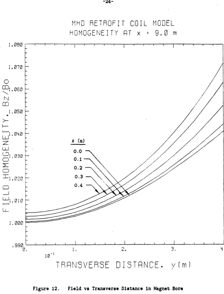
The on-axis field vs. distance along the axis is shown in Fig. 9, the field variations in bore cross sections are shown in Figs. 10, 11 and
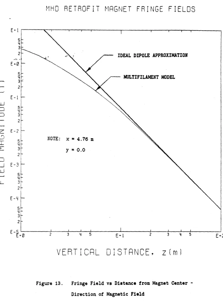
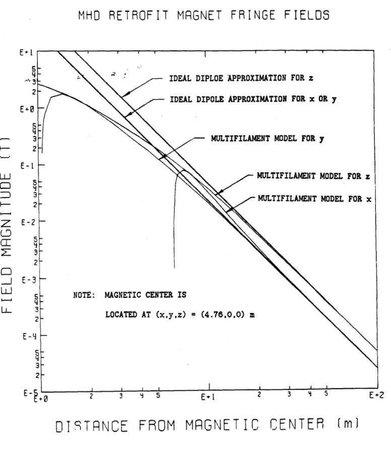
12, and fringe fields are shown in Figs. 13 and 14.
Typical computer graphic diagrams of stick models used in computing fields, together with diagrams showing force vectors, are given in Figs. 15,
16, and 17.
3.5.4 Structural Design Basis
The structural aspects of the retrofit-size magnet pre-conceptual design will be generally in accordance with "Structural Design Basis for Superconducting Magnets", Reference 10.
-6-Allowable stresses are to be identified according to the bases stipulated in the ASME Nuclear Power Boiler Code. They will be the lowest of the following:
Ferrous Materials Nonferrous Materials
* * * *
Atu/4, 5/8)t or (5/8)Ocy at/4, (2/3)aty or (2/3)y (* whichever is applicable)
The minimum numerical values for tensile ultimate strength (a
),
tensile yield strength (a ) and compressive yield strength (a
)
wilXUbe determined at the operating Vemperature of the structure, at the5
limit of the normal distribution curve.It is estimated that tensile stresses in critical sections of the force containment structure of the retrofit magnet pre-conceptual design shown on preliminary assembly drawing, Figure 1. will not exceed 60 psi, or
1/4 of the ultimate tensile strength of the preferred material (stainless steel 304 LN) at 4.5 K. The design will be further analyzed and upgraded to assure that stresses in all major elements are within allowable limits.
Particular attention will be given to structural properties of the winding and ICCS conductor. The effect of impregnation of the windings to provide a more uniform distribution of loading on the conductor will be analyzed.
4.0 Future Activities
During the next quarter, the conductor design requirements definition will be finalized, including functional requirements, system
interfaces, design criteria, and design parameters. Overall magnet system requirements will be formalized with APT personnel, development of a pre-conceptual design will continue based on these requirements, and the supporting analytical effort will continue.
5.0 References
1. MHD Magnet Technology Development Program Summary. Plasma Fusion Center. MIT, September 1982 (PFC/RR83-6).
2. MHD Magnet Technology Development Program Summary. Plasma Fusion Center, MIT, September 1984 (PFC/RR84-18).
3. NASA/LeRC Conceptual Design Engineering Report - MHD Engineering test Facility 200 MWe Power Plant, prepared for NASA/LeRC for DOE by Gilbert/Commonwealth, DOE/NASA/0224-1 Vol. I-V, September 1981. 4. Brogan, T. R.. MEPPSCO, Inc. Report. MHD Generator Superconducting
Magnet Packaging Study, prepared for Francis Bitter National Magnet Laboratory, MIT, August 1981 (MIT PO ML-162789).
5. Marston, P. G. et al, Magnet-Flow Train Interface Considerations, 19th SEAM, University of Tennessee Space InstituteJune 1981.
6. Wang, S. T. et al. The Fabrication Experiences and the Performance Test of the Coal-Fired Flow Facility Superconducting Dipole Magnet. 19th SEAM, University of Tennessee Space Institute, June 1981.
7. Hals, F. A.. et al. Results from Comparative Analysis of Different MHD Generator and Power Train Designs for Early Commercial Power Plant Applications, 21st SEAM. Argonne National Lab, June 1983. 8. Hatch, A. M. , et al, Impact of Design Current Density on Cost and
Reliability of Superconducting Magnet Systems for Early Commercial MHD Power Plants, 21st Symposium on Engineering Aspects of MHD. Argonne National Lab., June 1983.
9. Course Notes, Magnet Power Supplies and Protection, MIT Summer Session "Superconducting Magnet Design for MHD and Fusion," June 22-26, 1981.
10. Becker, H., Structural Design Basis for Superconducting Magnets, MIT/FBNML,(Internal Report), February 1980.
0 W 0 u
-8-r
c~
LA- .% % %0 wU CL co 07% U, ci. cor 0 % 00 W 'a~IA ta cr c V)- Ln IAw LA.. LI' % O U CLaJL '": 0 0M C 0 41GJ c. L. C (v CL La1 Lai *. r0 r- %, 'a 4/' 1 o 41 4A voL~ Lo P":-i. . 'acm.~ .9-'a EU U . 9-0. 0. .9c cc- 0 G0* * 6 *0 IA I C%j 0 4) L. 04) 4-1 &1 Ma "-W 41 a C C J 4J~ '-41 4) In V A 4-) 4) 'W ma U to x C 'a 'a V7C 'a; 0 C W W .0 .0 C1 W p 4C 0' 0 V C C0% 1. 20) u L) 06 4A.)a L. 4- 14- 'a 0 0 =w .1 Lu CR co z 4-01 EU .9-5*1 Vi) 0 Lin 0Table II
MHD System Parameters and Preliminary Magnet for Retrofit-Size MHD System
Westinghouse
Requirements
Avco
Plant thermal input Channel power output Channel type
Channel inlet dim. Channel exit dim. Channel active length Peak on-axis field Field at channel inlet Field at channel exit
(MWt)
(MWe)
(m)Cm)
Cm)
(T) (T)(T)
250 40 - 41 supersonic 0.45 sq. 1.00 sq. 11 - 11.6 4.5 to 6'0.5
3.0 275 35 - 40 supersonic 0.424 sq. 0.848 sq. 8 - 9 4.5 3.03.0
Notes:1. Westinghouse currently considers 6 T preferable but plans to investigate lower fields, down to 4.5 T.
-10-Table III
Selected Design Parameters for Retrofit MHD Magnet Pre-Conceptual Design
Value
Basis for SelectionPeak on-axis field (T) Warm bore dim. inlet (m)
Warm bore dim., exit (m) Bore util. factor, inlet Bore util. factor, exit Active length (m)
Design current density (average in winding)
4.5 Info. from APT contractors' 0.8 x 1.0 To provide room for channels
of sizes being considered by APT contractors2 1.3 0.22 0.41 9 x x
x
1.6
0.25 0.48(A/M
2) 3.8 to 4 x 10⁷ Past experiencesMiddle range of APT contractor data
To take full advantage of ICCS and to minimize magnet cost4
Notes: (1) 4.5 T being considered by Avco; range of 4.5 to 6 T being considered by Westinghouse. A 6 T alternative design magnet will be investigated later.
(2) See Table II.
(3) See Table I. Utilization factors selected at high side of range in interest of magnet cost reduction. See references 4
& 5.
(4) Winding using ICCS does not need substructure and hence can operate at higher current density. Higher current density leads to lower magnet cost. See Reference 8.
Table IV
Design Characteristics
Pre-Conceptual Design Retrofit-Size Magnet
Field and Bore Dimensions Peak on-axis field
Active length (3 T to 3 T) Warm bore inlet size
Warm bore exit size
(T)
Cm)
(m)
(m)
4.5 9 0.8 x 1.0 1.3 x 1.6 Overall Dimensions(m)
Cm)
(m)
LengthHeight including stack Width Winding Characteristics Winding configuration Conductor type Design current Build Ampere turns Inductance Stored energy
Winding current density (average) (kA) (m) (A) (H) (MJ) 12.2
6.3
5.2 Rectangular saddle ICCS (NbTi/Cu) 24 0.25 11.8 x 10⁶ 1.69 487(A/cm
2)
3870
-12-Table V
Preliminary Conductor Design Characteristics
Type Outside dimensions (cm) Sheath material Sheath thickness (cm) No. of strands Strand material Void fraction
Design current (kA) Maximum field (T)
Operating temperature (K) Coolant pressure (atm) Critical current (kA)
Copper to superconductor ratio Stability margin
Quench heating temperature rise (K) Design maximum internal pressure (psi) Minimum bend radius (cm)
Maximum continuous length (m) Maximum compressive load (psi) Maximum tensile load
ICCS 2.08 x 2.08 Stainless steel
0.165
486 NbTi/Cu 0.32 246
4.5 2.5 40 >5 TBD 260 14,00015
600 7250 TBDU I -'-4 0 0
I
*-0 '=- ~ I -ii I I. ii II II, ~, I -I-{_
-'---- *'*___I
I:Ii
III
1//i
II
III ii
i/
0-4 o iiI!
I I ii!,I,
II
4'
LI
*
II -vI
4 4 "I 9-4-'4-iii 0 C.
-K
or - - - I --/
I*4 0-3L
/ I I 0 .4 -43 -4 H .0 '43 0 .04 C0 0 o. to3 to/\/1 +'K~k~
* /1 FI',
-'I
H
2 I, * I '4 N 1' F NN N F F w A '43 .0 43 0 4 .PA
-16--r
_______i
flL7
F
/
N
Retrofit MHD Magnet Assembly, Section at Inlet
I ~ ~ N N N N N N N N NI
z
.
K.z
Retrofit MHD Magnet Assembly, Section at Exit C2 .Z 4 Z .Z
Z
h..tL/L L..2
400
300
200
CURRENT DENSITY IN COPPER (kA/cm2)
Curves of Temperature Rise in Conductor vs Current Density in Copper. Magnetic Field = 0 T
-18-I I I I I I I I DISCHARGE 50 20 10 5 TIME CONSTANT (5)
50
100
njw-50
20
35
10 20 Figure 6.i i I I I I I I Im DISCHARGE 50 20 10 5 TIME CONSTANT (s) I A i i I A A
5
10
20
S I50
CURRENT DENSITY IN COPPER (kA/cM2)
Curves of Temperature Rise in Conductor vs Current Density in Copper. Initial Magnetic Field = 6 T 400
300
200 100 Ez~50
20 3 Figure 7. I*
-3 S B 0 .5 0 0 / 4 -IF-.4 * 54
-4
W. --- ' El ~44 0 4 -5---*'I
+1
'-4 'lb 0 '-4 Co - 4~
,I*
43 043 4 0 5.4 0 0 r04 0 bO .9.4 0I
MHU RETROFIT PRELIMINPRY FIELDJ PROFILE ON PXIS
-.- - - - -- -4 - ---- - - - -
-3. It -- ----I: I I -. 2 to 1 0.. .6. . RXIR DISRC (m) 0.ue9 uv f n il sDitneAogAi
-22-MHD RETROFIT COIL MODEL
HOMOGENEITY PT
x
0.0
m
1.0
1.5
2.0
TPRNSVERSE
DISTRNCE,
y
(m)
Figure 10. Field vs Transverse Distance in Magnet Bore Cross Section Near Channel Inlet
1.06
0
N
m .04 bJ1.03 LDc~1.02
S1.01 -LJ .00.99
0
I
I I I I I I I I I I I I I I I z (m)0.0
0.1
0.2 0.3.5
10~1
2.5
3.0
t
.
MHD
RETROFIT
COIL MODEL
HOMOGENEITY
PT
x
1.0
m
1.0
1.
5
2.0
TPRNSVERSE
DISTRNCE,
y(m)
Figure 11. Field vs Transverse Distance in Magnet Bore Cross Section Region of Peak On-Axis Field
! I I. I I
1.030
020 0000
m
z
1.
N
LUJ
LD
O.
LLJ
990Z
0.0 - z =0.1m
z 0.2 m-.
'j '-'I'I ' I ' ' ' 980.9-70 I
.960 '
0.
10-1
2.5
3.0
I . NO I i I i I 010
-24-MHU
RETROFIT
COIL MODEL
HOMOGENEITY PT
x
9.0
m
I .
2.
THRNSVE98E DISTRNCE,
3.
Figure 12. Field vs Transverse Distance in Magnet Bore Cross Section Near Channel Exit
1.080
2.070
C
N
1.
~2.
WI.
. 060
050
040
030
020 0101.000
.990 0 z(m)
0.0
0.1 0.2 0.3 0.410~
4.v
(m)
,
MHO
RETROFIT
MRGNET FRINGE
2 3 L 5
FIELDS
2 3 4 5
VERTICRL
DISTRNCE,
Figure 13. Fringe Field vs Distance from Magnet Center -Direction of Magnetic Field
3 2
E-0
3 2 5 3, 2LU
z
-J
LU
U-IDEAL DIPOLE APPROXIMATION
MULTIFILAMENT MODEL
L
-NOTE: x 4.76 m y =0.0 I I I I I I 5 3 2E-Y
5 LA21
E+2
z
m
-26-MHD RETROFIT MRGNET FRINGE
FIELDS
E+1
S
y .,.3 2E-0
3 2E-I
LLJD
3 2E-2
2 LL 3 2E-Y
E+1
2 j TDIT9TPNCE
FROM MFGNETIC
CENTEP
(m
Figure 14. Fringe Field vs Distance from Magnet Axis (X-direction) and Perpendicular
(Y-direction) and (Z-direction)
Center Along
to Axis
IDEAL DIPLOE APPROXIMATION FOR z IDEAL DIPOLE APPROXIMATION FOR x OR y
MULTIFILA-ENT MODEL FOR y
MULTIFILAMENT MODEL FOR z
MULTIFILAMENT MODEL FOR x
NOTE: MAGNETIC CENTER IS
LOCATED AT (x,y,z) = (4.76.0,0) m
-~
- * L C
I6e 0 0 %4 0 0 4H 0 "q . Ea4 "I "r4 Ia. 4& \b