DOI 10.1007/s00107-005-0007-6
O R I G I N A L A R B E I T E N
·
O R I G I N A L SB. Stamm · J. Natterer · P. Navi
Joining wood by friction welding
Published online: 16 August 2005 ©Springer-Verlag 2005
Abstract At the Chair of Timber Constructions of the Swiss Federal Institute of Technology in Lausanne (EPFL) tests were carried out to join wooden work pieces by friction welding with-out any additional welding deposit. It could be determined that this kind of technology, which is mainly used for thermopla-stics and metal, can also be applied to wood. Tests were carried out to determine the influence of the processing parameters like welding pressure, frequency and amplitude of the circular mo-vement on the welding process and the input of energy at the interface. In addition, the resistance of the joint was exami-ned. The development of the shear strength during solidification of the interface as well as the shear strength achievable after a complete solidification of the interface was the objective of the examinations. Furthermore, the microstructure of the welded joint was studied to reveal the manner in which the thermally decomposed wood forms the connection between the welded pieces.
Herstellen von Holzverbindungen mittels Reibschweißen Zusammenfassung Am Lehrstuhl für Holzbaukonstruktionen der Eidgenössischen Technischen Hochschule Lausanne (EPFL) wurden Versuche durchgeführt, Werkstücke aus Holz durch Reibschweißen ohne zusätzliches Schweißgut zu verbinden. Es wurde festgestellt, dass diese Verbindungsmethode, die bisher hauptsächlich für thermoplastische Kunststoffe und Metalle An-wendung findet, ebenfalls auf den Werkstoff Holz angewendet werden kann. Die Versuche wurden durchgeführt zur Ermitt-lung des Einflusses der Prozessparameter wie Schweißdruck, Frequenz und Amplitude der zirkularen Reibbewegung auf den Schweißprozess und den Energieeintrag in die Oberflächen. Die Festigkeit der Verbindungen wurde ebenfalls ermittelt. Die B. Stamm (u) · J. Natterer
IBOIS–Chair of Timber Construction, Swiss Federal Institute of Technology Lausanne, 1015 Lausanne Switzerland
E-mail: bernhard.stamm@epfl.ch P. Navi
LMC–Laboratory for Construction Materials, Swiss Federal Institute of Technology Lausanne, 1015 Lausanne Switzerland
Entwicklung der Scherfestigkeit während dem Aushärten der Fuge und die erreichbaren Endscherfestigkeiten waren Teil der Untersuchungen. Mikrostrukturelle Betrachtungen der Schweiß-verbindung wurden durchgeführt, um zu klären, auf welche Art das thermisch umgewandelte Holz im Fugenbereich die Verbin-dung zwischen den verschweißten Holzstücken gewährleistet.
1 Introduction
This paper deals with the possibility of joining wooden pieces without any additional material using the technology of fric-tion welding. Sutthoff et al. (1996) made the first attempts for the joining of wood by means of pressure and frictional heat in Germany. Since the year 2000, the IBOIS is researching and de-veloping this method for wood connection (Gliniorz and Natterer 2000, Gliniorz et al. 2001). The realisation of wood-to-wood connections by means of frictional heat without any additional material is an innovative process with high potential for deve-lopment. The times necessary to complete a bond are shorter than one minute. No preparation of the welded surfaces is requi-red. The input of friction energy changes the wood surfaces in a way that they are “melted” together to form a single entity. The constituents of wood, mainly lignin, cellulose and polyoses, are polymeric as thermoplastic synthetics are. The difference bet-ween the two is that wood polymers are thermally decomposed and change by chemical reactions during the welding process, while thermoplastics stay the same with regard to their chemical composition.
One disadvantage of glued connections is the long time ne-cessary for the curing of the adhesives. Normally glued connec-tions require several hours of pressing. The short welding times during friction welding of wood could lead to better efficiency with regard to the time necessary to fabricate the connections. The phenomenon of melting wood is still new. No bibliogra-phical data could be found relating to the melting of wood in conjunction with thermal treatment. The chemical reactions taking place in consequence of the thermal treatment are un-known. The influencing parameters are, on the one hand, the
machine settings like welding pressure, frequency and ampli-tude of the movement, and on the other hand, the parameters of the material (species of wood, orientation of the annual rings, humidity, density and size). The friction force, the welding dis-placement perpendicular to the interface and the progression of temperature were measured to evaluate the influences of these parameters.
The resistance after a complete solidification of the interfa-cial layer was evaluated by shear tension tests. Examinations of the microstructure give an indication in which manner the adhe-sion between the welded parts takes place.
2 Experimental
The welding machine (Type Fischer ZMT 2) used for the experimentation was formerly designed for the welding of thermoplastics.
The parameters of welding pressure, frequency and ampli-tude of frictional movement, as well as the welding displacement can be adjusted on this machine.
A circular, horizontal movement is applied (as described by the circles on the surface of the upper specimen in Fig. 1). This movement guarantees a constant force and velocity during the entire welding process because the direction of the movement stays the same contrary to linear friction welding (during linear friction welding the velocity and force are oscillating and chan-ging the direction and are thus not constant). Abrupt changes can affect the molten mass.
The end of the welding process is fixed by the achievement of a preset welding displacement perpendicular to the interface. On the one hand this displacement is composed of the compres-sion of the specimen on the other hand a shortening occurs in consequence of the thermal decomposition of material at the heat affected zone.
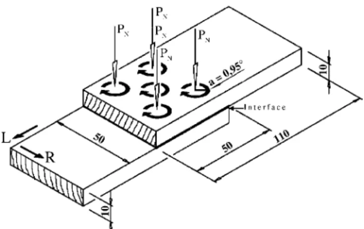
Fig. 1 Dimensions of the specimen with amplitude of circulation a in mm, normal pressure PN, orientation of the annual rings (L= longitudinal
direc-tion, R= radial direction)
Abb. 1 Abmessungen der Probekörper mit Amplitude a der Zirkularbewe-gung in mm, Normaldruck PN, Jahrringlage (L= longitudinale Richtung,
R= radiale Richtung)
2.1 Preparation and size of specimens
The specimens for the tensile shear testing were composed of two pieces of wood with dimensions 110× 50 × 10 mm. Two pieces were welded together at a 50× 50 mm2surface as shown in Fig. 1. During the welding process the upper specimen is rub-bing on the lower specimen, which is attached.
Norway spruce (Picea abies) and beech (Fagus sylvatica) were used for the tests. The surfaces of the boards were planed, to achieve constant surface properties. For reasons of homo-geneity, all specimens used were without any visible defects. Before testing, the specimens were stored under controlled con-ditions (293 K, 65% relative air humidity) in a climatic chamber. The average moisture content of the samples was 12.8% for the Norway spruce samples and 12.2% for beech. The density of the dried samples averaged 0.41 g/cm3 for Norway spruce and 0.69 g/cm3for beech.
2.2 Influence of normal pressure and welding frequency on the heat generation
Heat generation by frictional energy is required for the alteration of the solid wood close to the interface into a “molten” state and for the realisation of a bond. A certain temperature is necessary to reach the “melting” state.
Temperature profiles were taken using four thermocouples, which were installed through holes located underneath the spe-cimen and placed in the heat affected zone.
Simultaneously the friction force was measured biaxially in a horizontal direction during the entire welding process by force transducers.
A variation of the friction force occurs as a function of time and temperature during the thermal alteration of the interface.
The influences of the welding parameters frequency and
wel-ding pressure on the welwel-ding process, the friction force and the
progression of temperature were examined. These parameters are connected with the heat generation rate according to the follo-wing relations.
The shear stress at the interface due to Coulomb is given by:
τ = µPN (1)
whereµ is the coefficient of friction and PNis the welding pres-sure normal to the interface. The heat generation rate per cycle per area (q) can be calculated by
q= τv (2)
where v is the velocity of the frictional movement. By using Eq. 1, Eq. 2 becomes:
q= µPNv (3)
with
v = 2πa f (4)
where a is the amplitude of the circular movement and f is the welding frequency. According to these correlations the
genera-Table 1 Welding parameters and varying values of normal pressure and fre-quency
Tabelle 1 Schweißparameter und variierte Druck- und Frequenzeinstellun-gen
Parameter Dimension Values
Amplitude [mm] 0.95
Normal Pressure [MPa] 0.31 0.47 0.63 0.79 0.94
Frequency [Hz] 80 95 110 130 150
Thickness Specimen [mm] 10
Welding Displacement [mm] 0
tion of heat depends on the normal pressure, the coefficient of friction, the welding frequency as well as the amplitude of the circular movement a.
The pressure and frequency variations according to Table 1 have been chosen to understand the influence on the heating du-ring the welding process:
For each variation, five tests were carried out. The orienta-tion of the annual rings for these examinaorienta-tions was vertical to the interface with a deviance of±20◦.
2.3 Mechanical testing of the shear strength
2.3.1 Testing carried out immediately after the welding process To evaluate the process of solidification as a function of tempe-rature and time, shear tension tests were carried out. Five series of ten test samples each were welded and tested at different ti-mes shortly after the termination of the welding process. For all test series, the same settings of the welding installation were re-tained. The orientation of the annual rings of the specimens was perpendicular (±20◦) to the interface. The shear strength was evaluated with a special apparatus designed to measure the plane strain. Because this device is hand-operated, the chart speed could not be kept exactly uniform over the whole force range. Figure 2 shows the apparatus with its main components.
Table 2 shows a summary of the welding parameters, used for shear strength testing:
Fig. 2 Hand-operated measuring device used to measure the shear strength during solidification of the interfacial layer
Abb. 2 Handgesteuerte Messapparatur zur Bestimmung der Scherfestigkeit während der Aushärtung der Kontaktzone
Table 2 Welding parameters for shear strength examinations Tabelle 2 Schweißparameter für die Scherkraftuntersuchungen
Parameter Dimension Values
Amplitude [mm] 0.95
Normal Pressure [MPa] 0.63
Frequency [Hz] 130
Thickness Specimen [mm] 10
Welding Displacement [mm] 2
Cooling Time [s] 45
Cooling Pressure [MPa] 1.58
2.3.2 Tests carried out after a complete solidification of the interface
The shear strength of the welded samples (cured and condi-tioned under air humidity of 65%, temperature of 293 K for 21–24 days) was tested with a ZWICK 1495 universal te-sting machine with a chart speed of 0.05 mm/s. The shear tension tests were carried out along the longitudinal direc-tion of the samples parallel to the direcdirec-tion of the wood fi-bres according to EN 302-1. Each test series was composed of 15 samples. Defective welds could not be taken into ac-count. The welding parameters are the same as presented in Table 2.
2.4 Examinations of the microstructure of the heat affected zone
Different mechanisms of adhesion are likely to operate in this kind of connection method.
Factors such as the welding pressure, the deformation forces, the temperature and the humidity of the samples are of signifi-cance for the structural change at the interface during the frictio-nal movement.
Microscopic examinations of the heat affected zone and the adjacent regions of thermally changed and unchanged wood, re-spectively, shed light on the structure of the joint and the bond. The studies show in which way the joint material creates the con-tact to the adjoining areas. The thermal decomposition of the cell structure of wood can be considered as a function of the distance to the source of energy, the heat affected zone. The test samples were taken out of a cross-sectional cut perpendicular to the fibre direction. They were embedded in epoxy resin. The surface was polished by abrasive paper (5 microns) and observed by confocal microscopy.
3 Results and discussion
3.1 Temperature and coefficientof friction during the welding process
The examinations revealed that the friction force passes through different characteristic phases during the welding process, which
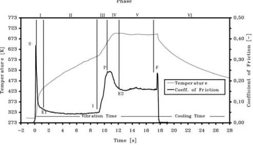
Fig. 3 Classification of the Process in different phases (I–VI) by means of the progression of the coefficient of friction as a function of the in-terfacial temperature (exemplary for a Norway spruce sample welded with a welding pressure PN= 0.78 MPa and a frequency of 130 Hz) and
characteristic points S, E1, I, P, E2, F Abb. 3 Unterteilung des Prozesses in verschiedene Pha-sen (I–VI) in Bezug auf den Reibkoeffizienten als Funktion der Temperatur der Kontaktzone (bei-spielhaft für einen Fichtenprobekörper, der mit einem Schweißdruck von PN= 0,78 MPa bei
ei-ner Frequenz von 130 Hz verschweißt wurde) und charakteristische Punkte S, E1, I, P, E2, F
are marked by representative points. By means of these charac-teristic points, the process can be subdivided into six different phases of friction and lubrication as given in Fig. 3.
• Phase I: During the initial Phase I of the welding process, the two pieces are brought in contact under a certain pres-sure (point S). The surface asperities are smoothed because of boundary friction. The relatively rough surface leads to a rampant increase of temperature in the beginning. At about 393 K, the graph shows a break, which is on the one hand caused by the vaporisation of the moisture, contained in the sample (12.8%). On the other hand, the polishing of the sur-faces caused by the frictional movement leads to a decrease of the coefficient of friction.
• Phase II: This phase (between E1 and I) shows a constant co-efficient of friction. Therefore, the increase of temperature is nearly linear.
• Phase III: Phase III starts with a rampant increase of the friction force (point I) accompanied by an incipient smoke generation. During this phase, the surfaces start to decom-pose due to the frictional heat at a temperature of approxima-tely 593 K. The friction force rises continuously and reaches a peak at point P. The increase is due to the thermal decom-position of the surfaces. It is assumed that the sliding friction is changing to lubrication during Phase III.
• Phase IV: The achievement of the maximal temperature of 693 to 713 K in Phase IV leads to an equilibrium of tempe-rature as well as the friction force (E2).
• Phase V: The characteristic of Phase V is the equilibrium of the friction force maintained until termination of the frictional movement (between E2 and F). This equilibrium is based on the generation of heat by frictional energy balanced by the “molten”, decomposed wood cells and the hot smoke expelled from the interface. Possibly the wood reaches a certain state of phase transition which leads to an energy balance and, therefore, an equilibrium of heat. According to Shafizadeh and Rowell (1984) the evaporation of levoglucosan and the volatile pyrolysis
pro-ducts, taking place in a temperature range between 573 and 773 K, is highly endothermic. Thus, the heat of eva-poration leads to a cooling effect. This phenomenon ap-pears to be responsible for the equilibrium of the maxi-mum temperature of about 693 to 713 K during the welding of wood as well. The measured temperature values differ clearly from those mentioned by Gfeller et al. (2004) in connection with linear friction welding of wood (443 to 493 K).
• Phase VI: This phase corresponds to the cooling of the specimen and the solidification of the “molten” material at the interface. This process leads to the completion of the connection.
The progression of both temperature and coefficient of fric-tion shown in Fig. 3 is typical for the welding of spruce wood. Beech shows a similar behaviour as a function of welding time. However, the increase of temperature at the beginning of the pro-cess is much faster for beech compared to spruce. This is in all probability a result of the different surface properties.
Fig. 4 Progression of temperature at different distances to the interface Abb. 4 Verlauf der Temperatur in unterschiedlichen Entfernungen zur Kon-taktzone
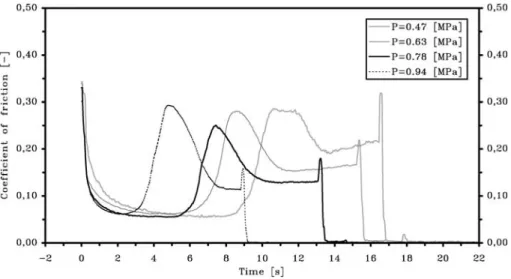
Fig. 5 Influence of welding pressure on the coefficient of friction
Abb. 5 Einfluss des Schweißdrucks auf den Reibkoeffizienten
Figure 4 shows the progression of temperature at different distances to the interface during the process. Due to the good insulation properties of wood, the wood matrix at a distance of 2.2 mm from the interface does not reach more than 385 K. This is about a forth of the interface temperature. Therefore, the heat remains concentrated around the interface where it is needed. No greater energy losses occur.
The wood structure adjacent to the heat affected zone is not undergoing major structural changes in consequence of high temperatures. By means of the retardation and the height of the temperature peaks measured by the different thermocouples the conduction and storage of heat can be retraced.
3.1.1 Influence of welding pressure1
Figure 5 shows the progression of the coefficient of friction at different pressure values. For each pressure option, a series of five samples was welded. The different measured gradients were averaged.
The welding pressure has a distinct influence on the wel-ding time. It can be seen that the welwel-ding time decreases with an augmentation of pressure (with a preset vertical displacement as a stop criterion). This effect is valid for all phases. The welding pressure of 0.31 MPa turned out to be too low to reach a satis-factory weld. All tests of this series had to be terminated before the achievement of the preset displacement after a preset wel-ding time of 40 s was reached. This maximum welwel-ding time was preset to avoid damages to the machine. Apparently, a certain pressure in combination with frequency is required to generate the heat that is necessary to modify the interface in the favoured way and thus reach a satisfying connection. This observation was made during friction welding of metal (Vairis and Frost 2000) as well. The maximum temperatures reached at the interface, for all tests, were nearly identical with values between 693 and 713 K.
The value of the coefficient of friction during Phase V decre-ases with increasing pressure. This behaviour could be a result
1According to Table 1
of a change of temperature or due to the variation of the nor-mal pressure PN. As the temperature stays nearly constant for the different tests it is assumed that the increasing pressure leads to a decreasing coefficient of friction (viscosity).
It is supposed that a shear thinning effect (non-Newtonian behaviour) takes place during the state of lubrication, as it is common for other polymeric compounds.
3.1.2 Influence of welding frequency2
The influence of a variation of frequency on the welding process was evaluated by the progression of the coefficient of friction as well. Figure 6 shows the coefficient of friction as a function of time for different frequencies of the circular movement.
The different curves illustrate the dependency of the wel-ding process on the frequency in every phase of the process. During Phases II–V, the coefficient of friction declines with an increase in frequency. In Phase II this behaviour is proba-bly due to the faster sliding on the surfaces. The possibility
2According to Table 1
Fig. 6 Influence of welding frequency on the coefficient of friction Abb. 6 Einfluss der Schweißfrequenz auf den Reibkoeffizienten
of the surface asperities getting stuck is reduced due to the higher velocity. In Phase V the temperatures increase with an increase in frequency. This leads to a lower viscosity of the “molten” material and, therefore, a decrease of the frictional force. Contrary to the pressure variation, the period of time to reach this state, as well as the entire welding times, are not dependant on the frequency settings used. This is astonishing because the energy input to the interface increases with an in-crease of frequency and on that account the heat generation should rise. The welding times should for this reason, decre-ase as occurred for an augmentation of welding pressure. On the other hand leads the decreasing coefficient of friction, occur-ring with increasing frequency, to a decrease of frictional energy. This effect results in a prolongation of the welding time and compensates the increase of frequency concerning the energy input.
The energy produced using a welding frequency of 80 Hz was too low to obtain a weld in the specified time. Obviously, a certain energy limit has to be applied to obtain a wood-to-wood connection. Otherwise no weld can be formed. Vairis and Frost (2000) discovered a similar behaviour for the welding of metal.
3.2 Results of the tensile shear testing3 3.2.1 During solidification
Figure 7 displays the shear strength measured immediately af-ter the af-termination of the welding process (including 30 seconds of solidification at a cooling pressure of 1.59 N/mm2) at follo-wing times: 10 s, 30 s, 1 min, 5 min, and 15 min. For every time step, ten samples were tested. The temperature at the interface decreases during this period from over 673 K during the wel-ding process to less than 313 K after fifteen minutes. Already
3According to Table 2
Fig. 7 Shear strength as a function of time of solidification after the termi-nation of the welding process
Abb. 7 Scherfestigkeit als Funktion der Aushärtezeit nach Beendigung des Schweißprozesses
after 60 s, the interface temperature is lower than 373 K. Table 3 shows the test results with standard deviation.
Immediately after welding, the joints already show a shear strength of about 2 MPa. During the following period of fif-teen minutes, the strain increases to about 2.6 MPa. That de-monstrates that the shearing strain obtained immediately af-ter welding already reaches about 77% of the value afaf-ter fif-teen minutes. Due to the anisotropy and inhomogeneity of wood, the measured values show a marked scattering. As the joint already shows shear strength of 2 MPa immediately af-ter welding, a continuous welding of several layers of wood onto each other without any break between the welding steps is possible (maximum shear during welding approximately 0.5 MPa). Figure 8 shows a cuboid consisting of eight alterna-ting layers of spruce and beech wood. The surfaces have been cut and grinded. The dimensions of the represented cuboid are 6.3 × 4.5 × 9.1 cm3.
Several species of wood have been examined with regard to weldability. Welded joints could be realised for all tested wood species. These are spruce, larch, birch, oak, and beech.
3.2.2 After solidification
The maximal shear force reached by beech wood was 4.2 MPa. Spruce wood could be loaded to a maximal shear force of 3.3 MPa. Table 4 shows the maximum average values and the standard deviation for two test series of beech and Norway spruce. The shear forces show a strong dispersion due to the ani-sotropy and inhomogeneity of the material wood. In the majority of the tests, the rupture takes place between the interfacial layer and the cell structure. The shear strength of the joint is about a third of the shear strength of natural wood.
Table 3 Results of the shear strength testing as a function of solidification time
Tabelle 3 Ergebnisse der Scherfestigkeitsuntersuchungen als Funktion der Aushärtezeit
Series Curing Time Number of Shear Strength Standard [s] Specimens tested [MPa] Deviation
SP01 10 10 2.04 0.28
SP02 30 10 2.21 0.41
SP03 60 10 1.86 0.39
SP04 300 10 2.51 0.38
SP05 900 10 2.57 0.49
Table 4 Maximum average values of the interfacial shear strength of beech and Norway spruce welds respectively
Tabelle 4 Maximale mittlere Scherfestigkeit der Verbindungsfläche von Buchen- bzw. Fichtenholzschweißverbindungen
Species Number of Shear Strength Standard Deviation Specimens [MPa]
Beech 14 3.2 0.39
Fig. 8 Cuboid composed of alternating layers of beech and spruce wood. This cuboid was fabricated in exactly the same manner as the tensile shear samples. The different layers were welded onto each other in intervals of about one minute
Abb. 8 Aus sich abwechselnden Buchen- und Fichtenholzschichten zusam-mengesetzter Quader. Der Quader wurde in exakt gleicher Weise hergestellt wie die Zugscherproben, wobei die einzelnen Schichten im Abstand von etwa 1 Minute aufeinander geschweißt wurden
3.3 The Microstructure of the Joint
Figure 9 presents an area of the joint, visualised with a confocal laser-scanning microscope.
As can be seen in picture B, the cell structure of wood is com-pletely destroyed at the interface. The material resembles a dense amorphous mass containing fragments of wood cells. The ca-vities of the cells have collapsed and are inexistent. The cells in the regions adjacent to the interface are densified by thermo-mechanical action, and the cell walls have collapsed as a result of the thermal influence and the forces of pressure and shearing. The effects of cell destruction at the interface and the adjoi-ning regions appear much less on annual rings of latewood. The thicker late wood cell walls with smaller voids are nearly intact, as it is shown in picture A.
The springwood cells with thinner cell walls are much more sensitive and can easily be destroyed. The mass of decomposed wood is enclosing the adjacent wood cells. This effect leads to an adhesion between the thermally decomposed material at the interface and the more or less unchanged regions of wood. The thickness of the interfacial layer varies. Annual rings angular to
Fig. 9 Microscopic pictures of the heat affected zone and the adjacent regi-ons (Picea abies, transverse plane)
Abb. 9 Mikroskopische Aufnahme der temperaturbeanspruchten Zone und der angrenzenden Bereiche (Picea abies, Axialschnitt)
Fig. 10 Undulated structure of the interfacial layer with varying thickness, indication of the zones shown in pictures A and B (Fig. 9)
Abb. 10 Gewellte Struktur der Schweißfuge mit unterschiedlicher Dicke, Bezeichnung der in den Aufnahmen A und B dargestellten Berei-che (Abb. 9)
the interface lead to an undulated structure, which varies concer-ning the interfacial thickness (Fig. 10), as can be seen as well in pictures A and B.
4 Conclusion
Friction welding of wood without any additional welding mate-rial is able to form wood-to-wood connections. As a result the shear strengths can reach up to 4 MPa (beech wood), which in-dicates the possible application in furniture industry and even in wood construction. The method allows an effective joining of wooden pieces without the requirement for a pre-treatment of the connected surfaces. The interface passes through diffe-rent phases during the welding process. The surface changes from solid to “molten”. This could be evaluated by a measu-rement of the friction force at the interface. The friction force shows a noticeable increase at a temperature of about 593 K. At this point smoke generation starts and the surfaces start to decompose in a visible way. The maximum temperatures reach values of about 713 K. The achievement of the maximum tem-perature leads to an equilibrium stage (for both the tempera-ture and the coefficient of friction) which is maintained until the termination of frictional movement. The maximum tempe-ratures were reached for nearly all the tests carried out. The
cooling of the interfacial layer at a certain cooling-process pres-sure leads to a solidification of the “molten” thermally de-composed wood cells at the heat-affected zone. It is due to this solidification of the interfacial layer that the connection is formed.
The welding time depends on the energy input applied to the surfaces, which can be influenced by parameters like pressure, frequency and amplitude of the frictional movement. The influ-ences of welding pressure and frequency have been evaluated by carrying out parameter studies. An increase of normal pressure leads to a reduction of the welding time. In addition, the normal pressure influences the friction force.
Varying the frequency of the frictional movement revealed that a certain amount of energy is needed to convert the surfaces to reach an acceptable weld.
According to shear tensile tests, carried out immediately after the welding process, a shear stress of about 2 MPa can be app-lied to the connections directly after a solidification time of 10 s. Thus, multilayered components could be realised by continuous welding without damaging already existent joints.
The average shear strength obtained after a complete soli-dification of the joint reached for different test series values of 2.1 MPa for spruce wood and 3.2 MPa for beech wood.
During welding, the wood cells adjacent to the connected surfaces collapsed due to frictional forces. The generation of heat leads to a decomposition of the different wood components. The interfacial layer, which is responsible for the connection, consists
of pieces of ground wood cells embedded in a mass of “mol-ten” material. The “mol“mol-ten” material is thermally decomposed wood compounds. The interfacial layer encloses the adjoining cells that are compressed and transformed, but still connected to the wood matrix. This effect leads to an adhesion between the thermally decomposed material at the interface, and the more or less unchanged regions of wood and thus, to a permanent connection.
References
EN 302-1 Entwurf (2001) Klebstoffe für tragende Holzbauteile, Prüfverfah-ren, Bestimmung der Längszugscherfestigkeit
Gfeller B, Pizzi A, Zanetti M, Properzi M, Pichelin F, Lehmann M, Del-motte L (2004) Solid wood joints by in situ welding of structural wood constituents. Holzforschung 58(1):45–52
Gliniorz KU, Natterer J (2000) Holzschweißen – Innovative Verbindungs-technologien im Holzbau. In: Tagungsunterlagen, Symposium der Ligna Plus/Weltmesse für die Forst- und Holzwirtschaft in Hannover, pp 9–18 Gliniorz KU, Mohr S, Natterer J, Navi P (eds) (2001) Wood Welding. In:
Proceedings of the First International Conference of the European Society for Wood Mechanics, Lausanne, Switzerland, pp 571–574
Shafizadeh F, Rowell RM (eds) (1984) Pyrolysis and combustion. The chemistry of solid wood, advances in chemistry Series 207. American Chemical Society, Seattle Washington, pp 489–529
Sutthoff B, Franz U, Hentschel H, Schaaf A (1996) Verfahren zum reib-schweißartigen Fügen und Verbinden von Holz. Patentschrift DE 196 20 273 C2, Deutsches Patent- und Markenamt
Vairis A, Frost M (2000) Modelling the linear friction welding of titanium blocks. Mater Sci Eng A 292:8–17