Design and Evaluation of a Cantilever Beam-Type
Prosthetic Foot for Indian Persons with Amputations
by M
Kathryn M. Olesnavage
B.S. Mechanical Engineering
Massachusetts Institute of Technology, 2012
Submitted to the Department of Mechanical Engineering
ASSACHUSETTS INSTrflJTE OF TECHNOLOGY
AUG 15 2014
Li
RARI ES
AqCH$Eg
in partial fulfillment of the requirements for the degree of Master of Science in Mechanical Engineering
at the
MASSACHUSETTS INSTITUTE OF TECHNOLOGY June 2014
@
Massachusetts Institute of Technology 2014. All rights reserved.Signature redacted
A uthor ... ...
Department of Mechanical Engineering May 9, 2014
Certified by...
Signature redacted
e
Amos G. Winter, V
Assistant Professor of Mechanical Engineering
Z Thesi& Supervisor
Signature redacted
A
ccepted by ...
...
David E. Hardt
Professor of Mechanical Engineering
Graduate Officer
0Design and Evaluation of a Cantilever Beam-Type Prosthetic
Foot for Indian Persons with Amputations
by
Kathryn M. Olesnavage
Submitted to the Department of Mechanical Engineering on May 9, 2014, in partial fulfillment of the
requirements for the degree of
Master of Science in Mechanical Engineering
Abstract
The goal of this work is to design a low cost, high performance prosthetic foot in col-laboration with Bhagwan Mahaveer Viklang Sahayata Samiti (BMVSS), in Jaipur, India. In order to be adopted, the foot must cost less than $10 USD, be mass-manufacturable, and meet or exceed the performance of the Jaipur Foot, BMVSS' current prosthetic foot. This thesis investigates different metrics that are used to design and evaluate prosthetic feet and presents an analysis and evaluation of a solid ankle, cantilever beam -type prosthetic foot.
Methods of comparing prosthetic feet in industry and in academia are discussed us-ing a review of literature. These comparisons can be categorized into mechanical, metabolic, subjective, and gait analysis comparisons. The mechanical parameters are the most useful for designing a new prosthetic foot, as they are readily translated into engineering design requirements; however, these are the furthest removed from the performance of the foot. On the other end of the spectrum are metabolic and subjec-tive parameters, which are useful in evaluating prosthetic feet because the objecsubjec-tives of minimizing energy expenditure and earning user approval are clear. Somewhere between these is gait analysis. The literature review reveals that not enough infor-mation is available to bridge these categories, that is, there is no consensus on how any particular mechanical parameter affects the subjective ranking of a prosthetic foot. Two mechanical parameters emerge as necessary, but not sufficient: the roll-over shape and the energy storage and return capacity of a prosthetic foot.
A simple model of a solid ankle, cantilever beam - type prosthetic foot is analyzed in the context of these two parameters. By applying beam bending theory and pub-lished gait analysis data, it is found that an unconstrained cantilever beam maximizes energy storage and return, but does not replicate a physiological roll-over shape well regardless of bending stiffness. Finite element analysis is used to find the roll-over shape and energy storage capacity from the same model when a mechanical constraint is added to prevent over deflection. The results show that for very compliant beams,
the roll-over shape is nearly identical to the physiological rollover shape, but the en-ergy storage capacity is low. For stiff beams, the opposite is true. Thus there is a trade-off between roll-over shape and energy storage capacity for cantilever beam -type feet that fit this model. Further information is required to determine the relative importance of each of these parameters before an optimal bending stiffness can be found.
A proof-of-concept prototype was built according to this model and tested in In-dia at BMVSS. It was found that another parameter - perception of stability, which is perhaps dependent on the rate of forward progression of the center of pressure -is equally important as, if not more than, the other parameters investigated here. Perception of stability increased with bending stiffness. The prototype foot received mixed feedback and has potential to be further refined. However, the solid ankle model is inappropriate for persons living in India, as it does not allow enough true dorsiflexion to permit squatting, an important activity that is done many times a day in the target demographic. Future work will use a similar method to design and optimize a prosthetic foot with a rotational ankle joint to allow this motion.
Thesis Supervisor: Amos G. Winter, V
Acknowledgments
I would like to thank the following people, all of whom were instrumental in the completion of this thesis:
* My family, for their love and support
" Prof. Amos Winter, for pushing me to achieve things I thought impossible and for giving me the freedom to pursue my own interests
* Mr. Mehta, Dr. Mathur, Dr. Pooja Mukul, Rajendra and Jitendra at BMVSS, for taking the time out of their busy schedules to facilitate this project
" Namita Sharma, for her help translating and for making me feel at home in India
" Paul Suresh, for making sure I didn't miss out on a single opportunity to try new food and for never giving up in his quest to teach me to speak Hindi * My labmates, for always being there for me as sounding boards and for never
failing to have my back
" My friends and roommates, for never letting me go too long without laughing * Dr. Rob Stoner, Prof. Charlie Fine, Dr. Nevan Hanumara, Dr.
Vaishnav and the Tata Center for making this work possible
9 All of the people I have met and interacted with in India, at BMVSS and elsewhere
I am also greatly appreciative to the following programs, without whom this work would not have been possible:
Ida M Green Fellowship
Tata Center for Technology and Design MIT India Innovation Fund
Contents
1 Introduction
1.1 Typical Human Gait and Biomechanics . . . . 1.2 Preliminary Interactions with People Using Jaipur Limbs . . . . 1.3 Design Requirements for New Prosthetic Foot . . . . 1.4 Outline of Thesis . . . . 2 Evaluating and Measuring Prosthetic Foot Performance
2.1 Introduction . . . . 2.2 Prosthetic Foot Comparisons In Industry . . . . 2.2.1 American Orthotic and Prosthetic Association Prosthetic Foot
P roject . . . . 2.2.2 ISO 22675 . . . .
2.3 Prosthetic Foot Comparisons in Academia . . . .
2.3.1 M ethod . . . .
2.3.2 Results and Discussion . . . . 2.4 D iscussion . . . .
2.5 Conclusion . . . .
3 Theoretical Considerations for a Mechanically
tilever Beam - Type Foot
3.1 Introduction . . . . 3.2 Unconstrained Cantilever Beam Model . . . . 3.3 Constrained Cantilever Beam . . . .
. . . . 32 . . . . 34 . . . . 35 . . . . 35 . . . . 36 . . . . .. . . . . 48 . . . . 5 1 Constrained Can-59 59 65 68 13 15 20 24 24 31 31 32
3.3.1 Finite Element M odel . . . . 70 3.3.2 M ethod . . . . 70 3.3.3 Results. . . . . 76 3.4 Discussion . . . . 77 3.5 Prototype Testing . . . . 83 3.5.1 M ethod . . . . 84
3.5.2 Results and Discussion . . . . 85
3.6 Conclusion . . . . 86
List of Figures
1-1 Internal Cross-Section of a Jaipur Foot . . . . 14
1-2 Anatomical Reference Planes . . . . 16
1-3 Ankle Plantar and Dorsiflexion . . . . 17
1-4 Ankle/Foot Anatomical Terms of Location . . . . 18
1-5 Power Output at Ankle During Typical Gait Cycle . . . . 20
1-6 The roll-over shape of a foot . . . . 21
1-7 Semi-structured interview responses for ease and importance of various activities . . . . 23
3-1 Transition from gait analysis parameters to beam bending parameters 65 3-2 Hypothetical force versus displacement curve for cantilever beam . . . 67
3-3 Analytical roll-over shapes for unconstrained cantilever beams with uniform cross-section for various bending stiffnesses . . . . 68
3-4 Force versus displacement curves for cantilever beams that are too compliant, too stiff, and ideal . . . . 69
3-5 FE model of constrained cantilever beam foot . . . . 71
3-6 Calculating roll-over shape from FEA results . . . . 73
3-7 Roll-over shape results from FEA of constrained cantilever beams of various bending stiffnesses . . . . 76
3-8 Force versus deflection curves resulting from FEA of constrained can-tilever beams of various bending stiffnesses . . . . 78
3-9 Trade-off between roll-over shape and energy storage capacity for con-strained cantilever beams of various bending stiffnesses . . . . 79
3-10 Implications for energy storage capacity for hypothetical foot that en-gages second cantilever beam in late stance . . . . 82 3-11 Subject taking a step with the proof-of-concept prototype prosthetic
List of Tables
1.1 Phases of Gait Cycle [18] . . . . 18 1.2 Demographic information for semi-structured interview participants . 22 1.3 Design requirements for prosthetic foot . . . . 25 2.1 Search criteria used in Compendex Database and Inspec Database . . 36 2.2 Description of metrics, test setup and feet investigated in mechanical
foot comparison studies . . . . 38 2.3 Outcomes of studies using mechanical metrics to compare prosthetic feet 39 2.4 Descriptions and outcomes of studies using subjective comparisons of
prosthetic feet . . . . 42 2.5 Descriptions of studies using metabolic parameters to compare
pros-thetic feet . . . . 42 2.6 Outcomes of studies using metabolic parameters to compare prosthetic
feet . . . . 4 3 2.7 Outcomes of studies using gait analysis to compare prosthetic feet . . 46 3.1 Example of effects of material choice on cantilever beam for range of
Chapter 1
Introduction
Bhagwan Mahaveer Viklang Sahayata Samiti (BMVSS), an NGO headquartered in Jaipur, India, is the largest organization serving persons with disabilities in the world [3]. Since its inception in 1975, BMVSS has fitted and/or distributed more than 1.3 million prosthetic limbs. In 2013, they provided over 24,000 limbs. The organization is sustained entirely through donations and government subsidies - all of the limbs and other assistive devices are supplied free of charge to people in need. This ser-vice is much needed; according to a report by the Indian Ministry of Statistics and Programme Implementation, published in 2003, 1,008 out of every 100,000 people in India have a locomotor disability, and 77 out of every 1,000 of those locomotor disabilities are due to loss of limb [15]. Based on these survey results, 0.08% of the population, or nearly 960,000 people are missing some part of a lower limb [4]. The global prosthetics market as a whole is expected to reach US$23.5 billion by 2017 [6].
The most widely known product from BMVSS is a prosthetic foot called the Jaipur Foot - in fact, the organization itself is commonly referred to as Jaipur Foot. The foot was developed in Jaipur in 1968 in response to the SACH foot - or Solid Ankle, Cushioned Heel foot - failing to suit the specific needs of Indian persons with am-putations [21]. Unlike the SACH foot, which has a rigid keel, or internal structure, the Jaipur Foot allows users to squat, sit cross-legged, walk through mud and over rough terrain. The Jaipur Foot also mimics the appearance of a biological foot and
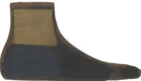
Figure 1-1: Internal Cross-Section of a Jaipur Foot is designed to be used either barefoot or with shoes.
The Jaipur Foot is handmade from wood and several types of rubber, as shown in Figure 1-1. Skilled technicians carve an ankle block from wood and a heel, fore-foot, and toes from microcelluar rubber compounds. The heel, forefore-foot, and toes are each coated in a vulcanizing cement, then wrapped with tire cord - a fiber-reinforced rubber tape. Next, the ankle block, heel, forefoot, and toes are assembled using the tire cord in a pattern mimicking the internal structure of a biological foot. The entire foot is then wrapped in a skin-colored rubber, enclosed in a mold and pressurized in an autoclave. Once removed, it is ready to be fixed to the rest of the prosthetic limb and used. The foot costs approximately $5-$10 to fabricate.
In addition to being inexpensive and suitable for the needs of Indian persons with amputations, the Jaipur foot is widely regarded as a relatively high performance pros-thetic foot. A study that compared the Jaipur foot to the SACH foot and the Seattle foot, a commercially available energy storing foot, using ground reaction forces found that the Jaipur foot allowed the most natural gait and enabled users to most closely replicated typical walkingf1]. In another study, the roll-over shape, or path of center
of pressure along the bottom of the foot (see Section 1.1 for more detailed description of roll-over shape), was measured for eleven types of prosthetic feet used across the developing world; of these, only the Jaipur Foot exhibited a circular roll-over shape, which is closest to the physiological shape, albeit the radius was smaller, which is likely due to increased dorsiflexion to allow squatting[19].
In 2002, BMVSS began working with the Indian Space Research Organization (ISRO) to design a polyurethane (PU) version of the Jaipur Foot [8]. The resulting foot would be lighter weight and mass-manufacturable, which is more efficient in terms of both time and money, and would allow for more consistent quality. Several PU prototypes have been made in collaboration with Dow Chemical, but none have matched the durability of the original rubber Jaipur Foot.
The goal of this work is to design a mass-manufacturable prosthetic foot that performs as well as, if not better than, the Jaipur Foot. In order to meet these difficult con-straints, it is necessary that we fully understand the governing behavior of prosthetic feet as well as the social factors that determine the design requirements.
1.1
Typical Human Gait and Biomechanics
Before any further discussion, several terms and parameters related to typical human biomechanics must be defined. Throughout the course of this thesis, the adjective "typical" will be used to describe anything pertaining to a person without amputation or other impairment, e.g. typical gait.
Biomechanical Terms
The three planes which are most commonly used to describe anatomical motions are the sagittal, coronal, and transverse planes, as shown in Figure 1-2. For the ankle joint, the primary motion during flat ground walking occurs in the sagittal plane. This motion is called dorsiflexion when the toes lift up toward the knee, and plantar
flexion when the toes point down away from the knee, as shown in Figure 1-3. The reference axes and the anatomical terms of location for a foot-ankle system are shown in Figure 1-4. Sagittal Plane Ct naI PImno Transverse Plane
KZZJ
Body PlamesFigure 1-2: Anatomical Reference Planes [20]
Typical Gait Cycle
The gait cycle covers one stride, or one complete sequence from the time one heel makes contact with the ground to the next time that same heel makes contact with the ground. There are many ways to break this cycle up into different phases. The simplest division is stance phase and swing phase. Stance phase occurs when the foot is in contact with the ground; the rest of the gait cycle is swing phase. Note that when one foot is in swing phase, the contralateral foot is always in stance phase. Each leg is in stance phase for about 60% of the gait cycle, and in swing phase the other 40%. This means that there is a period in time when both feet are in stance phase. This is called double limb support, as opposed to single limb support. The gait cycle
Dorsiflexion
Plantar flexion
Figure 1-3: Ankle Plantar and Dorsiflexion[16]
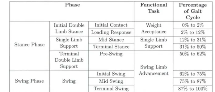
is further broken down by Perry into eight different phases, described in Table 1.1.
Palmer and Gates provide a different set of phases to describe the same events: con-trolled plantar flexion, concon-trolled dorsiflexion, powered plantar flexion, and swing phase [17, 5]. The definitions for these come from plotting the angle versus torque curve for the ankle, which can be broken up into these four segments. In each of these segments, the ankle exhibits a particular behavior, as described by the names of the phases. These are very useful in designing powered prosthetic foot-ankle systems, as sensors can be used to detect which of these phases the prosthesis is in at any given time and alter the output of the ankle according [2]. In passive prostheses, these phases are less useful, as the behavior of the prosthesis cannot be altered during gait. Most passive prostheses focus only on mimicking the behavior of the ankle during
ial
Plantar
Figure 1-4: Ankle/Foot Anatomical Terms of Location
Table 1.1: Phases of Gait Cycle [181
Phase Functional Percentage
Task of Gait Cycle
Initial Double Initial Contact Weight 0% to 2%
Limb Stance Loading Response Acceptance 2% to 12% Single Limb Mid Stance Single Limb 12% to 31% Stance Phase Support Terminal Stance Support 31% to 50%
Terminal Pre-Swing 50% to 62%
Double Limb
Support Swing Limb
Initial Swing Advancement 62% to 75% Swing Phase Swing Mid Swing 75% to 87%
Terminal Swing 87% to 100%
controlled plantar flexion and controlled dorsiflexion.
Two events that occur during the gait cycle that will be used frequently in this work are heel strike and toe-off. Heel strike refers to the instant that the heel hits the ground, and is usually the start of what is considered the gait cycle. Toe-off occurs when the toe of the foot leaves the ground; this marks the transition from stance phase to swing phase.
Ankle Power During Gait
A parameter that will be frequently discussed in prosthetic foot design is the energy storage and return capacity of a prosthetic foot. In order to investigate the function of this property, the mechanical energy provided by a biological ankle must be un-derstood. A plot of the power output at the ankle during the gait cycle is shown in Figure 1-5. The ankle does more positive work than negative work over the course of the gait cycle, and therefore is a net generator. During early and mid stance, the ankle absorbs energy. At push-off, there is a large burst of power that aids in transitioning to the contralateral foot. During swing phase, the biological ankle does a negligible amount of work in positioning the foot in preparation for heel strike. For the typical gait cycle measured and published by Winter, the ankle did 26.3 J of positive work and 4.9 J of negative work over the step for a subject of body mass 56.7 kg [23]. This and all other gait data used in this thesis comes from Winter's Biomechanics and Motor Control of Human Movement.
Roll-over Shape
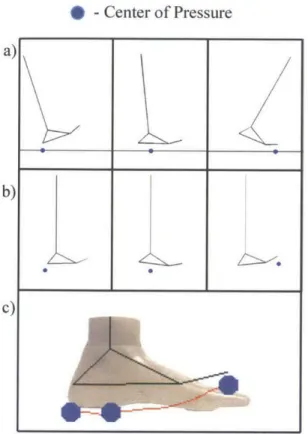
Another recurrent parameter in prosthetic foot design is the over shape. The roll-over shape is defined as the path of the center of pressure along the bottom of a foot from the time the heel hits the ground (heel strike) until heel strike on the opposite foot. This path is then rotated from the lab reference frame into the ankle-knee based reference frame, as shown in Figure 1-6. The concept of a roll-over shape builds on pre-existing rocker or rigid cam models of prosthetic feet [7, 11, 22, 18, 12, 10, 9, 13]. The resulting shape is roughly circular with a radius of 0.3 times the leg length [13].
10 20 30 40 50 60 70 80 90 100 Percentage of Gait Cycle
3ff
Stance Phase Swing Phase
Figure 1-5: Power output at ankle during typical gait cycle as measured by Winter for a person of body mass 56.7 kg [23]. Green area represents positive work, red area represents negative work. The ankle did 26.3 J of positive work and 4.9 J of negative work during the gait cycle shown here.
1.2
Preliminary Interactions with People Using Jaipur
Limbs
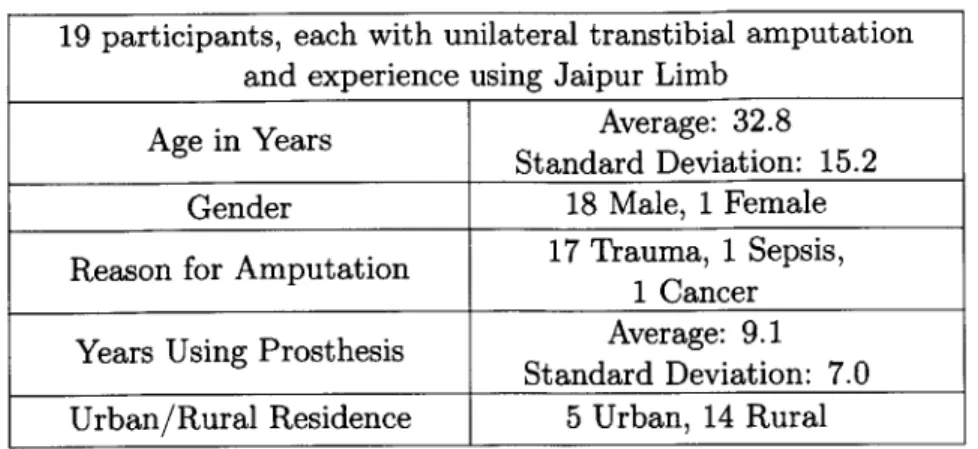
In January 2012, 19 people were interviewed with the help of a translator as they waited to receive limbs at BMVSS in Jaipur, India. Each participant provided in-formed consent verbally in accordance with a COUHES approved protocol. The participants were all persons with unilateral amputations. Demographic information about the participants is provided in Table 1.2.
Given a list of activities, each subject was asked whether they were able to per-form each activity with no difficulty, with some difficulty, or with great difficulty
300 - 250- 200- 150- 100-50 -C, 0 0 CL -50' 0 'I I 0
* -Center of Pressure
Figure 1-6: Illustration of obtaining the roll-over shape of a foot. The roll-over shape of a foot is defined as the path of the center of pressure along the foot from heel strike to opposite foot heel strike, rotated from (a) the laboratory reference frame to (b) the ankle-knee reference frame. The roll-over shape (c) comes from following this center of pressure through an entire step, and is shown here in red. The data used to create these plots comes from Winter's Biomechanics and Motor Control of Human Movement [23].
and whether each activity was very important, somewhat important, or not at all important. Thus the ease and importance of each activity was ranked from 0 (great difficulty
/
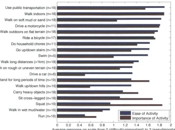
not at all important) to 2 (no difficulty/ very important). The average ease and importance ratings across all 19 subjects are given in Figure 1-7. The activities are displayed starting with the easiest activity at the top down to the most difficult at the bottom. The number of subjects that provided responses to the questions about the ease of each activity are provided in the activity description, as some people did not do all of the activities and thus could not answer.a)
b)
Table 1.2: Demographic information for semi-structured interview participants 19 participants, each with unilateral transtibial amputation
and experience using Jaipur Limb Age in Years Average: 32.8
Standard Deviation: 15.2
Gender 18 Male, 1 Female Reason for Amputation 17 Trauma, 1 Sepsis,
1 Cancer Years Using Prosthesis Average: 9.1
Standard Deviation: 7.0
Urban/Rural Residence 5 Urban, 14 Rural
The general order of the activities is as could be expected; activities such as walking indoors and walking outdoors on flat terrain were ranked easier than running, walking in wet mud or water, and walking up or down hills. The importance of most activities is less than or equal to the ease of those same activities, which suggests that these activities did not present any issue for the persons using the Jaipur Foot. However, a few of these activities, namely standing for long periods of time, carrying heavy objects, sitting cross-legged and squatting, were ranked as important and difficult. Upon further investigation and discussion with the Jaipur Foot users, most of these are due to problems with the prosthesis as a whole, and cannot be addressed by a new foot alone. Sitting cross-legged, squatting, and standing for long periods of time were difficult primarily due to discomfort caused by the socket. A new foot does however provide an opportunity to address difficulties in carrying heavy objects. Subjects reported that carrying heavy objects - particularly uphill - is difficult as the foot gets "stuck". It seems to the author that under the increased load, the foot dorsiflexes more than preferred. As a result, the user must first unload the prosthetic limb by lifting it straight up before he can proceed to move forward. It should be noted that the Jaipur Foot provides a greater degree of dorsiflexion than many feet in order to allow users to squat, so there may be a trade-off between the stiffness required to carry heavy objects and the compliance required to squat.
Use public transportation (n=19) Walk indoors (n=1 8) Walk on soft mud or sand (n=18)
Drive a motorcycle (n=1 1)
Walk outdoors on flat terrain (n=18) Ride a bicycle (n=17)
Do household chores (n=1 1)
Go up/down stairs (n=19) Swim (n=5) Walk long distances (>1km) (n=18) Walk on rough or uneven terrain (n=18) Drive a car (n=6) Stand for long periods of time (n=19) Walk up/down hills (n=16) Carry heavy objects (n=1 8)
Sit cross-legged (n=18)
Squat (n=19) Walk in wet mud/water (n=16)
Run (n=16) Ease of Activity
Importance of Activity
I I I I I I I J
0 0.2 0.4 0.6 0.8 1 1.2 1.4 1.6 1.8 2 Average response on scale from 0 (difficult/unimportant) to 2 (easy/important)
Figure 1-7: Semi-structured interview responses for ease and importance of various
activities. Perception of ease of activities is generally as expected. Three activities stand out as being difficult and important: standing for long periods of time, sitting cross-legged, and squatting, and carrying heavy objects. While all of these present potential areas for improvement, standing for long periods of time, sitting cross-legged, and squatting were perceived as difficult due to socket discomfort rather than the prosthetic foot technology. A stiffer foot could improve users abilities to carry heavy objects, but this is in opposition to the increased ankle dorsiflexion required
for squatting.
children, playing cricket, and watering wheat plants in a field. Additional activities that participants stated they would like to be able to do included running in races, climbing electrical poles to return to a job held prior to amputation, driving an
rick-shaw, and general farming.
The majority of the complaints participants had were about the socket - several complained of poor fit, pistoning, and discomfort, sweating, and chaffing due to the fully enclosed socket in India's hot, humid environment. These subjects were at the
BMVSS facility in order to be fit with a new prosthesis, so it is possible that these socket issues were mostly due to the subjects' residual limbs changing size and/or shape since their last visit to the facility. The only areas for improvement suggested by subjects about the foot were that it is slippery in muddy or wet conditions, and that they wish it lasted longer. The Jaipur Foot lasts comparably long to feet used in the western world, but it is the least durable of the components that make up a prosthesis. Thus, most of the time when Jaipur Foot users return to BMVSS to get a new limb, it is because the previous foot broke. Increasing the durability of the foot would let the people using the Jaipur Foot go longer between limbs, which would require fewer trips to BMVSS, which can take days. People have been known to lose their jobs when taking time off to travel to BMVSS and receive a new limb, decrease the frequency of these trips by increasing prosthetic foot durability will result in a huge improvement.
1.3
Design Requirements for New Prosthetic Foot
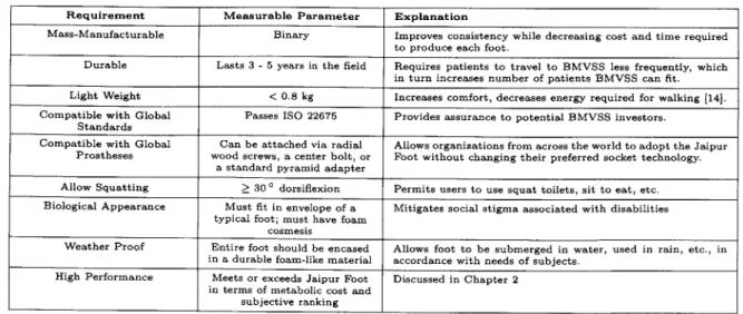
Based on interaction with the leadership team at Jaipur Foot, interviews with per-sons using Jaipur limbs, and a review of literature, a set of design requirements has been elucidated in order for a new prosthetic foot to be a viable product. The design requirements are as listed in Table 1.3 below. Several of these will be elaborated in the body of this thesis.
1.4
Outline of Thesis
This thesis describes the work that lead to the design and testing of a preliminary prototype. A literature review was used to determine what metrics can be used to design and evaluate prosthetic feet. The literature review suggested that two metrics are required to achieve symmetric and efficient gait: the roll-over shape and energy
Table 1.3: Design requirements for prosthetic foot
Requirement Measurable Parameter Explanation
Mass-Manufacturable Binary Improves consistency while decreasing cost and time required to produce each foot.
Durable Lasts 3 -5 years in the field Requires patients to travel to BMVSS less frequently, which in turn increases number of patients BMVSS can fit. Light Weight < 0.8 kg Increases comfort, decreases energy required for walking [141. Compatible with Global Passes ISO 22675 Provides assurance to potential BMVSS investors.
Standards
Compatible with Global Can be attached via radial Allows organizations from across the world to adopt the Jaipur Prostheses wood screws, a center bolt, or Foot without changing their preferred socket technology.
a standard pyramid adapter
Allow Squatting > 30 0 dorsiflexion Permits users to use squat toilets, sit to eat, etc. Biological Appearance Must fit in envelope of a Mitigates social stigma associated with disabilities
typical foot; must have foam cosmesis
Weather Proof Entire foot should be encased Allows foot to be submerged in water, used in rain, etc., in in a durable foam-like material accordance with needs of subjects.
High Performance Meets or exceeds Jaipur Foot Discussed in Chapter 2 in terms of metabolic cost and
subjective ranking
storage and return. A simple model of a cantilever beam-type prosthetic foot was created. The roll-over shape and energy storage and return capacity of such a foot were calculated using beam bending theory and FEA. A prototype was built and tested at BMVSS in Jaipur, India. An outline of the thesis is as follows:
Chapter 2: Evaluating and measuring prosthetic foot performance Methods of quantifying differences between prosthetic feet, both in industry and in academia, were reviewed in order to determine what metrics are useful for a) designing and b) evaluating a prosthetic foot. Various categories of types of measurements that can be made with prosthetic feet are described; the merits and limitations of each are discussed. The implications of this literature review for prosthetic foot designers are presented.
Chapter 3: Analysis and testing of a cantilever beam-type foot A
prosthetic foot is modeled simply as a cantilever beam fixed beneath a solid ankle. Using published gait data and beam bending theory, the roll-over shape of this foot is found over a range of beam bending stiffnesses. This reveals that a rigid constraint is necessary to mimic a physiological roll-over shape. A constraint is added to the model. Finite element analysis is used to
approximate the roll-over shape and energy storage capacity for this model; trends emerge for each of these as the bending stiffness is varied. A
proof-of-concept prototype foot is built based on these models and tested in the gait lab in BMVSS in Jaipur. Gait data and subjective feedback are discussed.
Chapter 5: Conclusion The important results from the preceding chapters are discussed. Future work is recommended based on the results found herein.
Bibliography
[1] A. P. Arya, A. Lees, H. Nirula, and L. Klenerman. A biomechanical comparison of the SACH, Seattle and Jaipur feet using ground reaction forces. Prosthetics
and Orthotics International, 19:37-45, 1995.
[2] S. K. Au, H. Herr, J. Weber, and E. C. Martinez-Villalpando. Powered ankle-foot prosthesis for the improvement of amputee ambulation. Conference proceedings
: ... Annual International Conference of the IEEE Engineering in Medicine and
Biology Society. IEEE Engineering in Medicine and Biology Society. Conference,
2007:3020-6, Jan. 2007.
[3] Bhagwan Mahaveer Viklang Sahayata Samiti. Jaipurfoot.org. http: //www.
jaipurfoot.org.
[4] CIA. The world factbook. http: //www. cia. gov/library/publicat ions/ the-world-f actbook/geos/in. html.
[5] D. H. Gates. Characterizing ankle function during stair ascent, descent, and level walking for ankle prosthesis and orthosis design. Master's thesis, Boston University, 2004.
[6] Global Industry Analysts Inc. Orthopedic prosthetics -a global strategic business report. Technical report, Research and Markets, March 2012.
[7] A. H. Hansen, D. S. Childress, and E. H. Knox. Prosthetic foot rollaARover shapes with implications for alignment of transaARtibial prostheses. Prosthetics
[8] Hindu Business Line Bureau. Rocket science for lighter 'jaipur foot'. www.
thehindubusinessline.in.
[9] M.-S. Ju. The modeling and simulation of constrained dynamical systems - with application to human gait. PhD thesis, Case Western Reserve University, USA,
1986.
[10] M.-S. Ju and J. M. Mansour. Simulation of the double limb support phase of human gait. Journal of Biomechanical Engineering, 110(3):223-9, Aug. 1988. [11] E. H. Knox. The role of prosthetic feet in walking. PhD thesis, Northwestern
University, 1996.
[12] H. Koopman. The three-dimensional analysis and prediction of human walking. PhD thesis, University of Twente, The Netherlands, 1989.
[131 T. McGeer. Passive Dynamic Walking. The International Journal of Robotics
Research, 9(2):62-82, Apr. 1990.
[14] Y. S. Narang. Identification of design requirements for a high-performance, low-cost, passive prosthetic knee through user analysis and dynamic simulation. Mas-ter's thesis, Massachusetts Institute of Technology, 2013.
[15] National Sample Survey Organization. Disabled Persons in India. Technical Report 485, Ministry of Statistics and Programme Implementation, Government of India, New Delhi, India, 2003.
[16] OpenStax College. Anatomy & physiology. Connexions Web Site. http: //cnx. org/content/co111496/1.6/, June 19 2013.
[17] M. Palmer. Sagittal plane characterization of normal human ankle function across a range of walking gait speeds. Master's thesis, Massachusetts Institute of Technology, 2002.
[18] J. Perry and J. M. Burnfield. Gait Analysis: Normal and Pathological Function. Slack Incorporated, second edition edition, 2010.
[19] M. Sam, A. H. Hansen, and D. S. Childress. Characterisation of prosthetic feet used in low-ARincome countries. Prosthetics and Orthotics International, 28(2):132-140, Jan. 2004.
[20] SEER Training Modules. Anatomy & physiology. U.S. National Institutes of Health, National Cancer Institute http://training.seer.cancer.gov/ anatomy/body/terminology.html, 22, May. 2014.
[21] P. K. Sethi, M. P. Udawat, S. C. Kasliwal, and R. Chandra. Vulcanized rubber foot for lower limb amputees. Prosthetics and Orthotics International, 2:125-136, 1978.
122] J. L. Stein and W. C. Flowers. Stance phase control of above-knee prostheses: knee control versus SACH foot design. Journal of Biomechanics, 20(I):19-28, 1987.
[23] D. A. Winter. Biomechanics and Motor Control of Human Movement. John Wiley & Sons, Inc, fourth edition edition, 2009.
Chapter 2
Evaluating and Measuring Prosthetic
Foot Performance
2.1
Introduction
As explained in Chapter 1, the motivation behind this work is ultimately to design a low cost, high performance foot for persons with amputations in India. In order to be adopted by the author's partner organization in India, Jaipur Foot, a prosthetic foot needs to cost less than $10 USD, be mass-manufacturable, and meet culturally specific user needs, such as allowing squatting and walking barefoot in harsh environments, as well as allowing the user to walk comfortably. In order to accomplish these goals, it is critical that we understand how individual features of prosthetic feet, such as stiffness and energy storage and return affect the performance of the prosthetic foot. By fully understanding the relationship between features and function, the design of the foot can be optimized to minimize the cost while maintaining high performance.
While there are a wide variety of passive prosthetic feet commercially available, there is a lack of information available to quantify and understand differences in prosthetic feet [16, 30, 3]. Many studies have attempted to characterize types of prosthetic feet based on mechanical testing, gait analysis, energy consumption, and user perception, but results have been inconsistent and largely unable to distinguish differences
be-tween feet [7, 25, 26, 29, 28, 11].
The purpose of this literature review is to 1) identify metrics that can be used to evaluate performance of a prosthetic foot, 2) determine design requirements based on these metrics, and 3) develop an understanding of the state of the science in pros-thetic foot design so that work can be focused in a direction that fits with existing literature and contributes to the field. In order to accomplish this, methods of com-paring prosthetic feet are broken down into two categories. First, methods that are used by prosthetic foot manufacturers to compare prosthetic feet are discussed along with their merits and limitations. Then a review of selected literature is presented covering methods that have been used to compare prosthetic feet in academia. From this, conclusions are drawn about which metrics are best to focus on for design and evaluation of prosthetic feet. Because the strict constraints on cost and durability in order for the foot to be adopted in the developing world, this review is focused only on passive prosthetic components.
2.2
Prosthetic Foot Comparisons In Industry
2.2.1
American Orthotic and Prosthetic Association Prosthetic
Foot Project
Medicare Healthcare Common Procedure Code System (HCPCS) assigns codes to commercially available prosthetic feet and uses these for reimbursement purposes. The purpose of these codes is to label prosthetic feet according to function and ensure that prosthetic feet are appropriately prescribed based on activity levels and needs of the patient. Beginning in 2007, the American Orthotic and Prosthetic Association (AOPA) Coding & Reimbursement Committee (CRC) established a Prosthetic Foot Project Task Force to create and recommend coding standards for prosthetic feet. The Prosthetic Foot Project Task Force worked with prosthetic foot manufacturers to develop these tests based on what was known about existing feet.
Eight different mechanical tests using a material testing machine, such as an In-stron or an MTS, were established in the final report. For full details and images of each of these tests, see the AOPA Prosthetic Foot Project Report [4].
Each of these tests dictates a setup to test the displacement of the foot in a par-ticular plane at a prescribed load. Threshold result values are given for each of these tests. Based on whether or not the foot exceeds the threshold value, it falls into a certain category. Codes, called 'L' codes, are assigned to prosthetic feet for insurance purposes depending on the categories into which it falls. For example, one test, the keel test, is described below in detail.
The keel test measures dorsiflexion of the foot to determine keel type. The foot is positioned at an angle of 20 degrees relative to a flat plate with the toes in contact with the plate. The foot is loaded to 1230 N and then unloaded. If the foot displaces less than 25 mm under a load of 1230 N, it is considered to have a rigid keel. If the foot displaces more than 25 mm, and the ratio of the area under the load versus displacement curves during unloading is less than 75% of that during loading (that is, of the work the loading machine does on the foot, the foot does less than 75% of that on the machine during unloading -the rest is dissipated), then the foot is considered to have a flexible keel. If the foot displaces more than 25 mm and the ratio of the area under the load versus displacement curves during loading and unloading is greater than 75%, the foot is considered to have a dynamic keel.
Other tests classify the foot as having a dynamic or a cushioned heel based on energy return and displacement during heel loading, single axis based on amount of dorsi-flexion, multiaxial based on compliance in motions other than sagittal dorsidorsi-flexion, namely sagittal plantar flexion and coronal inversion. Further tests less relevant to the work at hand include the axial torque absorption test, the vertical displacement test, the dynamic pylon test, and the horizontal displacement test.
It is noted in the final report that the threshold testing values are based off of com-mercially available products and are not indicative of clinical safety or effectiveness. However, these are the most widely used tests in industry and thus merit some dis-cussion.
A negative consequence of these tests and of HCPCS L codes is that some researchers misinterpret the categories defined by the tests and L codes as binary, and neglect that most of the properties fall on a spectrum with a threshold defined such that the foot falls into one of two categories. An example is that dynamic keel feet are sometimes called energy storage and return (ESAR) feet. Feet are often discussed as though they either store and return energy, or they do not. In reality, the amount of energy a foot can store, the amount of energy a foot can return, and the manner in which that foot stores and returns energy all vary and have significant affects on the performance of the foot. Several researchers have grouped feet based on these categories and expected to find similar behavior within one category, even though the feet are vastly different mechanically. These studies have failed to find consistent behaviors within categories of feet [25, 26, 12].
However, these tests do provide a consistent set of metrics across prosthetic feet that are helpful in prescribing and comparing prosthetic feet.
2.2.2
ISO 22675
The purpose of ISO 22675 is to prove safety and durability of a prosthetic foot. The standard describes a test that replicates the loading a prosthetic foot sees during a step. In order to pass ISO 22675, a prosthetic component must undergo three million cycles of this loading without failure, representing approximately three years of use [19].
the testing apparatus described in ISO 22675 loads the foot vertically about a plat-form that rotates to create the same relative motion. The vertical load on the foot and the relative angle between the foot and the pylon are given at 30 ms intervals for the 600 ms loading cycle, which is repeated with a frequency of 1 Hz. The whole test takes roughly one month to complete.
While ISO 22675 is slow and expensive (ranging from $144,000 to $250,000 for a commercially available testing setup), a prosthetic foot must pass this test to be adopted as a product. No developing world feet were able to pass the previous ISO standard, ISO 10328, a simplified version of ISO 22675 which was the only standard until 2006 and is still in use as an alternative to ISO 22675 [[20]]. Passing ISO 22675 with a prosthetic foot intended for developing countries would open the door for large international organizations, such as UNICEF or USAID to endorse the product. It would also make the product stand out from other options when NGOs that distribute prosthetic feet make decisions about which types of prosthetic components to use.
2.3
Prosthetic Foot Comparisons in Academia
Literature reviews published as recent as 2009 have found insufficient information available from clinical studies to describe the effects of prosthetic foot and ankle components, which are needed to enable prosthetists to make informed prescriptions for their patients [16, 30]. This is largely done based on empirical knowledge and the personal experience of the prosthetist. This section investigates studies that were published after these literature reviews as well as studies dating as early as 2000 that were not included in these literature reviews in order to determine whether any insight can be gained.
2.3.1
Method
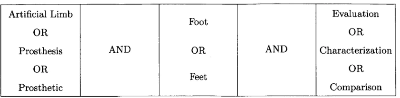
A search of the literature was performed using the Compendex Database and Inspec Database from 2000 to present using the criteria shown in Table 2.1. The search was
Table 2.1: Search criteria used in Compendex Database and Inspec Database
Artificial Limb Evaluation
Foot
OR OR
Prosthesis AND OR AND Characterization
OR OR
Feet
Prosthetic Comparison
also extended to include references from the identified articles.
Based on titles and abstracts, journal articles were included in this review when they compared three or more passive prosthetic feet, either commercially available or experimental prototypes. Studies were excluded when:
1. The study was included in either the Hofstad or van der Linde literature
reviews mentioned above.
2. The study used subjects with levels of amputations other than transtibial.
3. The study investigated only powered prostheses.
4. The study was written in a language other than English.
Studies were not evaluated by their methodological quality; that is, sample size, study population homogeneity, randomization, etc. had no effect on whether the study was included.
2.3.2
Results and Discussion
Based on the criteria listed above, 17 studies were selected for inclusion. The metrics used to compare prosthetic feet fell into four categories: mechanical, metabolic, sub-jective, and gait parameters.
Mechanical comparisons used metrics that can be measured with a test setup in-dependently of anyone using the prosthesis. The AOPA tests and the ISO 22675 test used by prosthetic foot manufacturers as discussed in Section 2.2 fall into this category. Mechanical metrics are the most useful in designing a foot, as they map directly to design requirements and can often be understood in terms of fundamental principles of engineering. However, they are furthest removed from human use sce-narios, which ultimately determine the success of a prosthetic foot. The goal of many of the papers discussed herein is to understand how these mechanical features affect the function of prosthetic feet.
At the other end of the spectrum are subjective and metabolic comparisons. These are directly related to the performance of a prosthetic foot, and desirable outcomes are well understood. Since persons with amputations expend more energy to walk than persons without amputations [8], one of the goals of prosthetics is to lower en-ergy expenditure during gait. Subjective comparisons are also very clear -satisfaction of the prosthesis user is the ultimate goal. However, both energy expenditure and subjective rankings are difficult to use as tools during early stage design, as they are dependent on many factors that are not necessarily known and cannot be tested until a foot is built.
In between mechanical comparisons and subjective and metabolic comparisons are comparisons based on gait analysis. Gait analysis provides a wide variety of parame-ters that can be used for comparison, some of which are clearly mapped to prosthesis superiority (e.g. self-selected walking speed), others of which are less clear (e.g. joint range of motion).
In the following sections, the studies that fall in each of these categories will be discussed and compared in order to understand the usefulness of each of the proposed metrics as both design and evaluation tools.
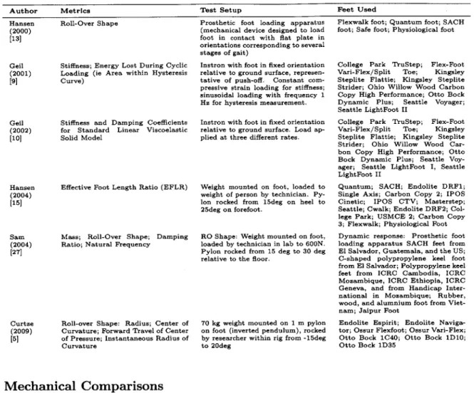
Table 2.2: Description of metrics, test setup and feet investigated in mechanical foot comparison studies
Author Metrics Test Setup Feet Used
Hansen Roll-Over Shape (2000)
[13]
Geil Stiffness; Energy Lost During Cyclic (2001) Loading (ie Area within Hysteresis
[9] Curve)
Geil Stiffness and Damping Coefficients (2002) for Standard Linear Viscoelastic
[10] Solid Model
Hansen Effective Foot Length Ratio (EFLR) (2004)
[15]
Sam Mass; Roll-Over Shape; Damping (2004) Ratio; Natural Frequency
[27]
Curtze Roll-over Shape: Radius; Center of
(2009) Curvature; Forward Travel of Center
[5] of Pressure; Instantaneous Radius of Curvature
Prosthetic foot loading apparatus (mechanical device designed to load foot in contact with flat plate in orientations corresponding to several stages of gait)
Instron with foot in fixed orientation relative to ground surface, represen-tative of push-off. Constant com-pressive strain loading for stiffness; sinusoidal loading with frequency 1 Hz for hysteresis measurement.
Instron with foot in fixed orientation relative to ground surface. Load ap-plied at three different rates.
Weight mounted on foot, loaded to weight of person by technician. Py-lon rocked from 15deg on heel to 25deg on forefoot.
RO Shape: Weight mounted on foot, loaded by technician in lab to 600N. Pylon rocked from 15 deg to 30 deg relative to the floor.
70 kg weight mounted on 1 m pylon
on foot (inverted pendulum), rocked
by researcher within rig from -15deg
to 20deg
Mechanical Comparisons
Six of the included studies used mechanical metrics as a mean to compare prosthetic feet. Table 2.2 and Table 2.3 describe the study design and outcomes respectively.
Four of these six studies focus on parameters related to the roll-over shape of a pros-thetic foot. Hansen introduces the roll-over shape and defines it as the path of the center of pressure from heel strike to opposite heel strike rotated into the ankle-knee reference frame [13]. It is a convenient metric, as it can be measured either mechan-ically or from gait analysis, and is equally applicable for all types of feet, including biological feet. He suggests that an objective in designing a new prosthetic foot is to produce a roll-over shape that replicates the roll-over shape as measured on a biolog-ical foot during typbiolog-ical walking, and ascertains that a prosthetist's goal in aligning a
Flexwalk foot; Quantum foot; SACH foot; Safe foot; Physiological foot
College Park TruStep; Flex-Foot Vari-Flex/Split Toe; Kingsley Steplite Flattie; Kingsley Steplite Strider; Ohio Willow Wood Carbon Copy High Performance; Otto Bock Dynamic Plus; Seattle Voyager; Seattle LightFoot II
College Park TruStep; Flex-Foot Vari-Flex/Split Toe; Kingsley Steplite Flattie; Kingsley Steplite Strider; Ohio Willow Wood Car-bon Copy High Performance; Otto Bock Dynamic Plus; Seattle Voy-ager; Seattle LightFoot I, Seattle LightFoot II
Quantum; SACH; Endolite DRF1; Single Axis; Carbon Copy 2; IPOS Cinetic; IPOS CTV; Masterstep; Seattle; Cwalk; Endolite DRF2; Col-lege Park; USMCE 2; Carbon Copy
3; Flexwalk; Physiological Foot
Dynamic response: Prosthetic foot loading apparatus SACH feet from
El Salvador, Guatemala, and the US;
C-shaped polypropylene keel foot from El Salvador; Polypropylene keel feet from ICRC Cambodia, ICRC Mozambique, ICRC Ethiopia, ICRC Geneva, and from Handicap Inter-national in Mozambique; Rubber, wood, and alumnium foot from Viet-nam; Jaipur Foot
Endolite Espirit; Endolite Naviga-tor; Ossur Flexfoot; Ossur Vari-Flex; Otto Bock 1C40; Otto Bock 1D10; Otto Bock 1D35
Table 2.3: Outcomes of studies using mechanical metrics to compare prosthetic feet
Author Outcomes
Hansen Roll-over shape of a prosthetic is defined and proposed as indicator of performance. Flexwalk foot had roll-over
(2000) shape nearly identical to physiological roll-over shape, which may explain its high performance in other published
[13] studies. Quasistatic properties of prosthetic feet determine the roll-over shape of a foot; prosthetists likely align foot such that roll-over shape of foot most closely matches orientation of physiological roll-over shape.
Geil Feet tested fell into four stiffness categories with little variation within each category. Flex-Foot lost least amount of (2001) energy during cyclic loading; College Park TruStep lost the most. However, Flex-Foot also required the least amount [9] of energy to load, so the percentage of energy lost was around average. All feet except Flex-Foot were tested with a
foam cosmesis.
Geil Prosthetic feet generally fit the standard linear viscoelastic solid model, with lowest R2 = 0.8982. The Flex-Foot and
(2002) College Park feet were least accurately modeled, possibly due to compliant ankles. Flex-Foot showed non-linearity
[10] in force versus deflection curve that was not captured. Most feet had similar damper coefficients, but Flex-Foot was significantly lower, most likely due to absence of foam cosmesis. Stiffness coefficients varied more than damping coefficients. A more robust model is needed to capture behavior of all types of feet.
Hansen Effective foot length ratio (EFLR) is defined as the distance from the heel to the most anterior position of the center (2004) of pressure during a step over the total length of the foot. For physiological feet during typical walking, EFLR was
[15] measured as 0.83. The EFLRs for the prosthetic feet studied here ranged from 0.63 to 0.81. A shorter EFLR may
lead to a 'drop-off' effect, in which the person using the prosthesis effectively falls onto his or her biological limb, resulting in asymmetrical step length and higher loads on the biological side.
Sam The mass of the prosthetic feet varied from 193.0 g to 854.6 g. The natural frequencies of all the feet were much (2004) higher than loading rate during normal walking, damping ratios were all low, such that dynamic properties were not
[27] likely to affect the performance of the feet during walking. All of the feet had SACH-like roll-over shapes, except
for the Jaipur Foot, which was circular with a radius smaller than that of a physiological foot. None of the roll-over shapes extended into the toes, which could lead to 'drop-off' effect.
Curtze Radius of roll-over shape for the prosthetic feet varied around 312 mm. Putting the prosthetic feet in shoes reduced
(2009) the radius of curvature. The horizontal position of the center of curvature varied greatly between prosthetic feet.
[5] The forward progression of the center of pressure on the ground with respect to the shaft angle is an 'S' shaped curve, and may be an important metric to include with roll-over shape measurements.
prosthetic foot is to orient the roll-over shape of the foot such that it best matches the roll-over shape of a biological foot.
Hansen's second study in this category investigated the effect of a single attribute of the roll-over shape, which he calls the effective foot length ratio (EFLR) [15]. It is defined as the ratio of the distance from the heel of the foot to the anterior-most point on the roll-over shape (the effective foot length) to the overall length of the foot. As with the roll-over shape, Hansen proposes that the optimal EFLR that which is closest to the physiological value, which he found to be 0.83. Hansen suggests that a prosthetic foot with too short of an EFLR results in what he calls a "drop-off" effect. In this case, the prosthetic foot is unable to support the weight of the person using the prosthesis as the center of pressure progresses out towards the toe. As a result, the person tends to fall onto his or her other limb, resulting in asymmetrical step lengths and higher ground reaction forces.
Sam measured the roll-over shapes and dynamic properties of 11 different feet used in developing countries, and found that the roll-over shapes of all but the Jaipur foot
resembled that of a SACH foot, which is mostly flat with a steep curve upward at the toes [27]. The Jaipur foot had a circular roll-over shape, which is close to what is seen from biological feet, but the radius was smaller than that of a biological roll-over shape. All of the feet studied here exhibited a small EFLR.
Curtze also investigated roll-over shape of commercially available prosthetic feet, but measured more individual parameters describing the shape: the radius, the horizontal center of curvature, the forward travel of the center of pressure, and the instantaneous radius of curvature [5]. While other studies have discussed radius and center of cur-vature [23, 24], to the author's knowledge, this is the first study that has considered the forward travel of center of pressure. This could be an important parameter, as a foot could exhibit a physiological roll-over shape but have very different rates of progression of the center of pressure along that path. Further work is required to determine how this particular metric influences prosthetic foot performance.
In both of his studies, Geil measured static and dynamic properties of feet using an Instron. The prosthetic feet are oriented in a position that mimics push-off and lowered to a flat surface such that the toes come in contact with the ground first. In his first study, Geil found the stiffness of the feet in this position by applying a constant strain rate and measuring stress. He then considered energy recovery prop-erties by applying a sinusoidal strain rate and measuring differences in work done in loading and unloading the foot. He found that stiffnesses of the different prosthetic feet on the market fell into one of four categories, with little variation within each category. Energy recovery varied much more. The Flex-Foot had the least amount of energy loss and was also the only foot tested without a foam cosmesis, which suggests that the cosmesis is responsible for most of the energy dissipation during loaded, as is expected [9].
In his 2002 study, Geil performed a very similar test, but modeled prosthetic feet using a standard model for linear viscoelastic solids - a spring in parallel with a
spring and damper in series. Three different constant strain rates were applied to prosthetic feet oriented relative to a flat plate in a position representative of push-off; the measured stress in each of these cases was used to find the damping coefficient and the stiffnesses in each of the springs in the viscoelastic model. Geil concluded that most of the feet tested fit the viscoelastic model very well, but it failed to capture the non-linearity of the Flex-Foot, which indicates a need for a more robust model. In the force versus displacement plots Geil presents, there is minimal difference in behav-ior for the different loading rates, which suggests to the author that a linear elastic model might be more appropriate for the loading of prosthetic feet in this manner. It appears that little benefit is gained by adding the complexity of a viscoelastic model [10].
Subjective and Metabolic Comparisons
Studies that use subjective questionnaires or metabolic measurements to compare prosthetic feet are discussed together because, unlike mechanical or gait analysis mea-surements, both subjective and metabolic metrics can clearly show the superiority of a prosthetic foot over another prosthetic foot. A prosthetic foot that allows a user to expend less energy while walking is superior to a prosthetic foot that requires more energy expenditure, and a prosthetic foot that people rank highly is superior to a prosthetic foot that people rank poorly. Determining what mechanical and gait anal-ysis parameters cause feet to be superior lacks a definitive answer. Thus subjective and metabolic metrics both provide useful evaluation tools for existing prosthetic feet.
Of the included studies, three used subjective preferences to compare prosthetic feet (Table 2.4), and five used metabolic parameters (Table 2.5). The outcomes of the studies performing metabolic comparisons are presented in Table 2.6.
Each of the studies using subjective metrics used different methods to achieve the results. Huang had subjects rank the comfort of each prosthetic foot on a scale from 0 - 7 during normal walking, walking on a slope, walking on grass, and fast walking.
![Figure 1-3: Ankle Plantar and Dorsiflexion[16]](https://thumb-eu.123doks.com/thumbv2/123doknet/14679001.558758/17.918.283.591.120.575/figure-ankle-plantar-dorsiflexion.webp)
![Figure 1-5: Power output at ankle during typical gait cycle as measured by Winter for a person of body mass 56.7 kg [23]](https://thumb-eu.123doks.com/thumbv2/123doknet/14679001.558758/20.918.169.695.117.561/figure-power-output-ankle-typical-measured-winter-person.webp)