Design of a Clutchless Hybrid Transmission
for a High-Performance Vehicle
The MIT Faculty has made this article openly available.
Please share
how this access benefits you. Your story matters.
Citation
Jacoby, Chad L., et al. “Design of a Clutchless Hybrid Transmission
for a High-Performance Vehicle.” ASME 2015 Power Transmission
and Gearing Conference; 23rd Reliability, Stress Analysis,
and Failure Prevention Conference, 2-5 August, 2015, Boston,
Massachusetts, ASME, 2015, p. V010T11A056.
As Published
http://dx.doi.org/10.1115/DETC2015-46812
Publisher
ASME
Version
Final published version
Citable link
http://hdl.handle.net/1721.1/117392
Terms of Use
Article is made available in accordance with the publisher's
policy and may be subject to US copyright law. Please refer to the
publisher's site for terms of use.
Proceedings of Proceedings of the ASME 2015 International Design Engineering Technical Conferences & Computers and Information in Engineering Conference IDETC/CIE 2015 August 2-5, 2015, Boston, USA
DETC2015-46812
DESIGN OF A CLUTCH-LESS HYBRID TRANSMISSION FOR A
HIGH-PERFORMANCE VEHICLE
Jake Jurewicz∗
Graduate Research Assistant Department of Nuclear Engineering Massachusetts Institute of Technology
Cambridge, Massachusetts Email: jure@mit.edu
Guillermo Pamanes Graduate Student School of Engineering Sloan School of Management Massachusetts Institute of Technology
Cambridge, Massachusetts Email: guillermopamanes@gmail.com
Young Suk Jo Graduate Research Assistant Department of Mechanical Engineering Massachusetts Institute of Technology
Cambridge, Massachusetts Email: yjo@mit.edu
Patricia X.T. Yen†
Graduate Research Assistant Department of Mechanical Engineering Massachusetts Institute of Technology
Cambridge, Massachusetts Email: paxty@mit.edu
Joshua E. Siegel Graduate Research Assistant Department of Mechanical Engineering
Massachusetts Institute of Technology Cambridge, Massachusetts
Email: j siegel@mit.edu
Chad L. Jacoby
System Design and Management Fellow School of Engineering
Sloan School of Management Massachusetts Institute of Technology
Cambridge, Massachusetts Email: cjacoby@mit.edu
Daniel S. Dorsch Graduate Research Assistant
Global Engineering and Research Laboratory Department of Mechanical Engineering
Massachusetts Institute of Technology Cambridge, Massachusetts
Email: dorsch@mit.edu
Amos G. Winter, V
Global Engineering and Research Laboratory Department of Mechanical Engineering
Massachusetts Institute of Technology Cambridge, Massachusetts
ABSTRACT
There exists the potential for major simplifications to cur-rent hybrid transmission architectures, which can lead to ad-vances in powertrain performance. This paper assesses the tech-nical merits of various hybrid powertrains in the context of high-performance vehicles and introduces a new transmission con-cept targeted at high performance hybrid applications. While many hybrid transmission configurations have been developed and implemented in mainstream and even luxury vehicles, ultra high performance sports cars have only recently begun to hy-bridize. The unique performance requirements of such vehicles place novel constraints on their transmissions designs. The goals become less about improved efficiency and smoothness and more centered on weight reduction, complexity reduction, and perfor-mance improvement. To identify the most critical aspects of a high performance transmission, a wide range of existing tech-nologies is studied in concert with basic physical performance analysis of electrical motors and an internal combustion engine. The new transmission concepts presented here emphasize a re-duction in inertial, frictional, and mechanical losses. A series of conceptual powertrain designs are evaluated against the goals of reducing mechanical complexity and maintaining functional-ity. The major innovation in these concepts is the elimination of a friction clutch to engage and disengage gears. Instead, the design proposes that the inclusion of a large electric motor en-ables the gears to be speed-matched and torque-zeroed without the inherent losses associated with a friction clutch. Addition-ally, these transmission concepts explore the merits of multiple electric motors and their placement as well as the reduction in synchronization interfaces. Ultimately, two strategies for speed-matched gear sets are considered, and a speed-matching proto-type of the chosen methodology is presented to validate the fea-sibility of the proposed concept. The power flow and operational modes of both transmission architectures are studied to ensure required functionality and identify further areas of optimization. While there are still many unanswered questions about this con-cept, this paper introduces the base analysis and proof of concept for a technology that has great potential to advance hybrid vehi-cles at all levels.
1 Introduction 1.1 Motivation
The transmission plays a vital role in the transfer of power from an engine to an automobile's wheels. Connected to the out-put of a vehicle's power source, transmissions allow the selection of multiple gear ratios to modulate the power and speed that are applied to the wheels.
∗Address all correspondence for other issues to this author.
†Address all correspondence related to ASME style format and figures to this author.
While transmissions have been studied and commercially used for decades, a renewed interest in hybrid gas-electric vehi-cles has emerged as the impact of anthropogenic climate change has become a global concern [1]. European and American regu-lators have instituted yearly targets for fuel economy and carbon emissions, and car manufacturers that do not meet these targets face heavy fines [2]. Of additional concern to automobile manu-facturers is CAFE, or Corporate Average Fuel Economy. CAFE targets in the U.S., and similar programs around the world, in-centivize fuel efficiency and penalize manufacturers that fail to meet emissions goals. [2].
1.2 Hybrid Vehicles
Hybrid gas-electric vehicles address this global concern, as they can increase fuel economy by leveraging the electric mo-tor when the internal combustion engine (ICE) is not operating efficiently. In mild hybrid configurations, a battery and small electric motor (EM) help power the vehicle so the ICE can shut off when the vehicle stops. Full hybrid configurations use larger EMs and batteries that can independently power the car for short time times and at low speeds [3]. With an electric motor, instant torque is available. Combustion engines, in contrast, suffer inter-nal losses and do not develop peak torque until several thousand RPM [4]. Since EMs are best-suited to high-torque applications, they are often used to start the car from a stop. The ICE powers the car during normal cruising when it runs most efficiently. The ICE can also power an EM while cruising, using it like a gener-ator to produce electricity that is stored in the batteries [3]. For high-performance situations, the ICE and EM can work simul-taneously to boost power to the wheels, combining torque via a power-split device (PSD), a form of continuously variable trans-mission (CVT).
Hybrid transmissions are used mainly on light-duty vehi-cles, however, there are benefits of implementing hybrid trans-missions in high-performance vehicles. Stricter government reg-ulations, such as the EU and American CAFE standards, both require increased fuel economy along with reduced greenhouse gas emissions from vehicles. High performance vehicles are not exempted. They tend to consume large amounts of fuel and are subject to fines due to CAFE, gas guzzler taxes, and other pro-grams designed to disincentivize excess consumption and emis-sions [2]. These environmental aspects and economic regula-tions are the main reasons why auto-makers in all segments are hybridizing drivetrains.
In high-performance vehicles, hybridization may also help improve acceleration. A hybrid transmission includes an EM that can complement ICEs across a wide range of engine and ve-hicle speeds. ICEs have low maximum torque in the low speed range (800-1500RPM) because the airflow going into the engine is limited at low engine speed, resulting in lower torque than in a higher speed range. However, the EM achieves the peak torque
FIGURE 1. Torque profiles of an EM and an ICE are shown. The EM provides extra low-end torque at low speeds
at low speeds as shown in Fig. 1, which compares the torque pro-files of an EM and an ICE across a full range. The torque values in the table are generated from a vehicle simulation tool called Autonomie [5].
The combination of EM and ICE power is most effective with turbocharged engines that have a torque profile that varies greatly with speed and where power lags behind throttle applica-tion. EMs can also provide additional power at lower cost versus increasing the power of an ICE.
The work described in this paper is from an academic col-laboration with Ferrari, a performance-car company that is ex-ploring hybrid solutions for their 458 model. The company is facing more stringent fuel economy requirements, and sees an opportunitiy for a hybrid vehicle more attainable than the LaFer-rari.
The project scope emerged from discussion with Ferrari and a series of interviews that asked ”what” the company acheived, rather than comments as to ”how.” This allowed our team to come up with a series of attributes to guide product development and measure success, without capturing unnecessary design bias.
From the needs of fuel economy, emissions targets, cus-tomer perception, differentiation, and expanding markets, a mis-sion statement emerged: to design a transmismis-sion facilitating a hybrid vehicle that weighs no more than the current ICE vehi-cle on which the hybrid is based, but with improved performance and emissions. A successful hybrid transmission would address these needs and deliver improved acceleration, the same or im-proved top speed, imim-proved efficiency, and the same or reduced mass and volume as the current combustion-only transmission.
Additional goals, beyond meeting or exceeding current per-formance and efficiency, were to be able to provide torque-filling capability between gears for smooth operation, to be able to ad-dress a provided list of vehicle operating conditions, and to keep
Ferrari 458 Fuel Efficiency 8km/m3 Acceleration (0-28m/s) 3.4s Top Speed 89m/s Kerb Weight 1485kg Torque-fill capable? No
TABLE 1. The final list of design targets to match or improve upon for a high-performance hybrid transmission [6]
the center of gravity low. Encouraged were outside the box ideas and fresh perspectives, while a few select metrics were deemed not of concern. The final list of design targets to match or exceed are in Table 1, with the requirement to design something ''small, light, and fast.''
1.3 Conventional Hybrid Vehicles
Hybrid vehicles are widely deployed today, primarily as a means of improving fuel efficiency rather than providing high-performance acceleration and top speed. However, there are sev-eral different hybrid powertrain variants with differing require-ments, constraints, advantages, and disadvantages. Perhaps the best known hybrid approach is that of a parallel hybrid, as found in the Toyota Prius. A parallel hybrid relies on a mechanical link-age between two power sources, either pre- or post-transmission. This link allows either or both power sources to accelerate the vehicle, allows an EM to regenerate upon deceleration, and al-lows the ICE to charge an EM while stationary. The flexibility in motor location allows motors to be used in the most appropriate, highest-efficiency location within the drivetrain, and the EM may be geared to achieve maximal impact [7]. The biggest disadvan-tages of this approach are mechanical complexity, mass, and the fact that the ICE is not run at peak efficiency, as it must change RPM along with vehicle speed (CVTs lessen, but do not elim-inate, this effect). In such a configuration, both power sources must be sized sufficiently large to operate the vehicle at reason-able performance levels, driving up size of engines relative to those used in series hybrid types [8].
Vehicles like the Chevy Volt use another hybridization strat-egy: the series hybrid approach. This platform allows an ICE to operate at its most effective speed and recharge a battery or di-rectly power an EM, using batteries as energy buffers. A series hybrid has the benefit of reduced ICE sizing, improved ICE effi-ciency, and a short charge path, but series hybrid vehicle perfor-mance is limited by the EM power and the ability of the batteries and charging circuitry to supply that EM.
(TTR), a method by which one driven axle is motivated by one power source, while the other axle has an alternative power source. An example is the Peugeot 3008 Hybrid4. The me-chanical constraints applied are a no-slip condition, which keeps the drive axle speeds similar. In effect, the road is used as the link between front and rear wheels, meaning energy can only be transmitted between axles while the vehicle is moving [9]. This is a primary disadvantage of TTR hybrids, as batteries cannot be charged while the vehicle is physically stationary. Also challeng-ing is the issue of ride smoothness, and ensurchalleng-ing stability due to differing power curves and control interfaces, and recharging re-quires a long path between the ICE and battery (doubled losses due to energy conversions) [10]. The advantage of the TTR ap-proach is typically four-wheel drive, partial torque vectoring for stability, and the elimination of a starter motor, as an EM mo-tor may easily accelerate the vehicle and use this motion to start an ICE, though the smooth engagement of the ICE is a chal-lenge [11]. Up until the traction limit, the use of dual axle drive significantly improves acceleration, and a front bias can provide stability in low traction situations. TTR hybrids are arguably the easiest hybrid technology to deploy, as one of the driven axles requires no architecture changes, and EMs may be small in size because low power motors may still deliver sufficient torque at low vehicle speeds. Therefore, implementation of a TTR hybrid is typically a problem dominated by packaging, rather than other technical limitations. While the individual motors are smaller, efficiency losses are higher in smaller motors, and therefore sys-tem efficiency decreases [12].
Several hybrid power architectures have been deployed in high-end supercars for added performance. Both the LaFerrari and the McLaren P1 make use of the parallel architecture [13,14]. The Porsche 918 Spyder offers an example of a TTR hybrid bined with a parallel hybrid in a performance vehicle. It com-bines a 608hp V8 engine, 154hp EM, and 7-speed dual clutch transmission connected to the rear wheels with a second 125hp EM connected to the front wheels [15]. In a performance con-text, low overall system weight and optimal utilization of every power-producing machine is desired over simply overall system efficiency. This drives automotive engineers to design a system that makes multiple uses out of as many components as possible. Designing motors for specific purposes, as in the series hybrid architecture, becomes undesirable. Adding a second drivetrain to the front wheels, as in the TTR hybrid architecture, becomes a tradeoff of added power versus added weight with little oppor-tunity for existing system simplification. Therefore, the paral-lel hybrid architecture is most desirable for the opportunities it presents to both simplify existing engine and transmission com-ponents as well as add low speed torque.
1.4 Existing Problems in Hybrid Technology
There are several concerns about translating conventional hybrid technology to high-performance vehicles. The Toyota Prius offers a prime example: the PSD has proven effective for efficiency-oriented consumer vehicles. In place of a tradi-tional transmission with a stepped gearbox, the PSD is a fixed-gear CVT. Although the PSD has proven effective for efficiency-oriented consumer vehicles, there are several potential concerns about using PSDs or other CVTs in high-performance appli-cations. One of the concerns is the complexity of controls to manage power sources. Most modern CVTs maximize torque for low-power vehicles. For high-performance vehicles, it may be difficult to program the controls to maximize power versus torque.
Another possible issue is poor driver experience, especially at high speed or high load conditions. Because the ICE can rev at any speed, the loss of the distinct engine scream and gear shifting may impact the driver's enjoyment of a performance vehicle. One possible remedy is to use synthetic gears to simulate traditional driver involvement.
The heating and wear of high performance driving could also increase the rate of repair for planetary gears. With increas-ing speeds, PSDs have demonstrated increasincreas-ing frictional losses that may eliminate the performance and efficiency advantages as engine power is scaled up [16]. With higher planetary gear rota-tion, gear meshing power is lost as heat that is distributed to sur-rounding parts. For an efficiency-oriented hybrid, the heated re-gions have reached 443K, suggesting that CVTs in performance vehicles will reach significantly higher temperatures [16].
1.5 Strategy, Concept and Implementation
After reviewing current hybrid system for conventional and performance vehicles, we produced a short list of important de-sign requirements:
1. Fully integrated into the vehicle
2. Maintain or improve upon current 458 acceleration and speed performance
3. Maintain or lower mass of existing 458 drivetrain
4. Maintain the performance-car experience and client’s repu-tation
5. Minimize part count and excess inertia
6. Remove excess legacy components that exist for the sake of the ICE, but could be replaced with the inclusion of a large electric traction motor
7. Capable of every hybrid operational mode, such as all-electric drive and charging while parked and moving Ultimately, we recommend using a parallel hybrid, pre-transmission approach to the vehicle manufacturer. This is be-cause the system has lower mass compared to TTR approaches,
so the power output is higher than a series approach, and the gear-ing allows the motor to be used across a wider speed range. The motor to ICE battery path is improved over a TTR approach; the parallel design can recharge while the vehicle is stationary, and the dynamics of a rear-wheel drive performance car are main-tained, with power delivery to the weighted wheels under accel-eration. Torque fill is easier to manage than in a TTR solution, as well.
A transmission parallel hybrid approach is not without risks, however, as using this approach makes possible sacrifices in ac-celeration and stability. We believe that these risks are mini-mal, as acceleration is near the traction limit already, and control strategies for vehicle stability are well-understood and available prepackaged from component suppliers.
2 Analysis
2.1 A Systems Approach
A system approach was taken to develop multiple design concepts. Starting with a clean slate and a list of the func-tions that a vehicle must perform, components were added to the conceptual transmission design to accomplish those functions. Strong priority was given to components that could enable mul-tiple functions. When selecting components to accomplish func-tions, further priority was given to configurations that reduced the volume, mass and rotational inertia of the design. This pro-cess resulted in a series of conceptual designs that utilized an EM to speed-match gear sets, eliminating the need for a fric-tion clutch. The conceptual designs also eliminated the need for a dedicated reverse gear and shaft by allocating that function to the EM and reduced the number of gear sets required by enabling the main transmission shaft to be connected to the engine at two different gear ratios.
Transmission efficiencies are in the approximate range of 84-92% [17]. The range varies depending on the operating con-ditions, vehicle configurations, and the age of the transmission. In a transmission, the major power losses are due to the transmis-sion oil pump and clutches. Pumping consumes about 30-40% of power, and the clutch consumes about 20-25% of power [18]. Clutch losses come from the fluid filled between them in the case of the 458 wet clutch. The fluids present within the clutch plates form an internal resistance, which form the shearing force. This force, due to the viscosity, generates a drag torque which be-comes a drag loss. These values suggest that removing a clutch will significantly increase transmission efficiencies.
2.2 Reducing Losses
To best focus design efforts, the main sources of transmis-sion losses were analyzed. Transmistransmis-sion losses can be divided into two main types: static and dynamic losses. Static losses are losses that do not depend much on the vehicle speed. Examples
include oil pumps, clutch pack drag, and bearing drags. Dynamic losses are inertial losses caused by the angular acceleration of ro-tating parts when the vehicle is accelerating. First, inertial losses were evaluated to see the effect of removing few rotating parts on the overall rotational inertia.
Using the kinetic energy equation of the vehicle in terms of vehicle speed and angular velocities of the wheels, a relation-ship was found between the equivalent rotational inertia and the equivalent mass of the whole vehicle [19]. Estimated rotational inertia of all the parts combined is 0.1286kg·m2which is about 4% of the equivalent moment of inertia. This implies that about 4% of energy is used only to rotate the transmission parts. It was found that the dynamic losses due to rotating parts are relatively low compared to the power required to operate the vehicle. How-ever, our main goal was to improve the efficiency of the transmis-sion; further research was done to validate how removing parts will be beneficial.
2.3 Reducing Mass
For high performance cars, mass is the most critical parame-ter to optimize. It deparame-termines the car's ability to accelerate, brake, and corner. Mass also plays a very important role in handling, which is a main area that characterizes high performance cars from ordinary vehicles. Therefore it is important to reduce as much mass as possible.
First-order weight calculations were carried out, and the re-sults show that one proposed embodiment for the concept of Minimum Part Count reduces the weight of the transmission by 1%, as shown in Table 2. It is significant considering that the baseline for the comparison was a non-hybrid transmission with-out motors, inverters, and batteries. The detailed comparison between the 458 transmission and the current design is in Ap-pendix A. The proposed concept carries additional weight due to electro-mechanical parts, but it still results in 1% lower mass by removing clutches, clutch oil, and few gears.
3 Design Concept: Clutchless Shifting 3.1 Concept Overview
Two architectural designs were selected for further feasibil-ity studies. In both concepts, the function of the clutch is re-placed with the combination of the ICE, EM and synchronizers to transfer power in all required hybrid operating modes.
3.2 Design 1: Speed-match with EM and ICE
In a traditional transmission, the primary function of the fric-tion clutch is to disconnect the source of torque and rotafric-tion from the transmission so that changes in the gear configuration can be made without damaging the gear teeth. As shown in Fig. 2, in the clutch-less transmission this function is handled by the car's
Current 1 EM 6sp Units Shafts 4 5 each Synchros 4 4 each Gears 19 14 each Clutches 2 0 each Transmission oil 3.9 3.2 L Clutch oil 7.0 0.9 L
Remainder (enclosure, diff) 72.5 100.4 kg
Scaled percent remaining 100% 70%
Total Transmission Weight 144.9 86.6 kg
Motors 0 1 each
Inverters 0 1 each
Wiring and cooling 0 1 each
Battery 0 1 each
Total Support Weight 0.0 57.0 kg
Total Weight 144.9 143.6 kg
Percent of baseline 100.0% 99.1%
TABLE 2. Weight estimation for the 458 and proposed system con-figurations
FIGURE 2. Design 1: Reduced number of gear-sets required by en-abling the main transmission shaft to be connected to the ICE at two different gear-ratios.
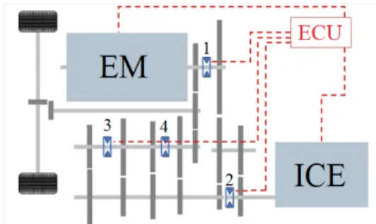
Electronic Control Unit (ECU) using speed-matching. The ar-chitecture of the clutch-less transmission places the ICE at the input of the transmission and a large EM near the output of the transmission. Since some ECUs are capable of having precise, closed-loop control over the speed of the ICE, the speed of the EM, and the position of the transmission synchronizers, this
con-FIGURE 3. ECU control paths are shown for speed-matching and shaft torque sensing
figuration gives the ECU control over the speed of all shafts and gears in the transmission. There has previously been discussion of using speed-match shift mechanisms to eliminate clutches in hybrid vehicles, but none with the same degree of weight savings and peak vehicle performance [20].
When the clutch-less transmission receives a command that requires it to mesh two gears, instead of disengaging the power source so the spinning gear can be slowed by friction to match the slower spinning gear, the ECU uses either the ICE or the EM to speed up the slower spinning gear to match the speed of the faster spinning gear. Once the two gears are spinning at the same speed, the ECU can shift the transmission synchronizer to mate the two gears. In addition to eliminating the need for a friction clutch, this process also eliminates the lag in acceleration that is traditionally associated with shifting gears because clutch-less shifting allows torque and acceleration to be transmitted to the wheels throughout the entire shifting process.
Torque needs to be monitored for both input and output shafts and their signals will be processed by the ECU to actu-ate the adequactu-ate synchronizers combination according to the re-quired function, as shown in Fig. 3. For launching from total stop, the EM will speed-up the wheels as synchronizers 1 and 2 are used to crank the ICE. As the ECU speed-matches the ICE, it will modulate synchronizer 2 to load the input shaft by friction until torque in both shafts is also matched, this modulation proce-dure is performed while one gear set is preselected in the output shaft. To disengage the gear set, the ECU regulates fuel flow to unload the input shaft as the EM fills in for torque using the final shaft, similar to the launching procedure, a modulated actuation of the synchronizers need to be included in the ECU software to command disengagement once the shafts are unloaded.
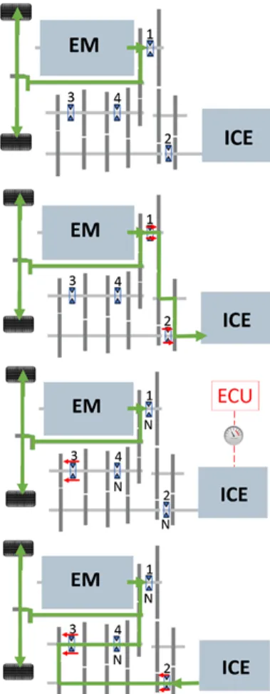
3.2.1 Shifting Sequence: Normal Mode In normal driving mode, the clutch-less transmission uses the EM for low-speed maneuvering in forward and reverse, with the ICE not run-ning. The launching and shifting sequence is described in Fig. 4. When the driver depresses the accelerator, requesting a speed higher than the EMs optimum speed range, the ECU uses the
FIGURE 4. Schematics of the launching and shifting sequence are shown
EM to accelerate while simultaneously shifting the synchronizer to connect the ICE with the primary transmission shaft. The ECU also starts the ICE and increasing its RPMs to match the speed of the #1 gear set with the speed of the transmissions secondary shaft. Once the speeds are matched, the ECU can shift the trans-mission synchronizer to mate the #1 gear set to the secondary transmission shaft and continue accelerating by increasing fuel flow to the ICE. Analysis of the torque graph for a 120kV EM indicates that the ECU would have approximately 1.5s to start the ICE and speed-match gears before the EM starts to reach the upper end of its optimal power band. This indicates that the orig-inal 458 0-100km/h (0-27.8m/s) time of 3.4s will be unchanged. When shifting to second gear, the ECU maintains power to the back wheels with the EM and decreases the speed of the ICE. When the torque across the #1 gear set drops to zero, the ECU disengages the transmission synchronizer from the #1 gear set, reduces the ICE speed to speed-match the #2 gear set to the secondary transmission shaft, and engages the transmission syn-chronizer to engage second gear. The same process is used to shift to third and fourth gear. A similar process will be used
for downshifting except instead of matching the speed of the two gears, the ECU will bring the torque on the gearset to zero before shifting the transmission synchro to disengage the gears. The ECU will acomplish this by either intantanously reducing power to the driving motor or with the use of torque sensors on the transmission shafts.
3.2.2 Shifting Sequence: Sport Mode If the driver selects sport mode, the shifting mechanics stay the same, but the ECU starts the ICE in advance and has it standing by at high idle, ready to be speed-matched and engaged. This mode will allow the ECU to respond more quickly to acceleration requests, but presents trade-offs in emissions and fuel efficiency.
3.3 Design 2: Speed-Match Using Two EMs
One of the challenges associated with implementation of the clutch-less shifting concept will be management of the delay and variability associated with the ECUs open-loop control of the output speed of the ICE. The ECU can control fuel injection rates, air intake, and ignition timing to affect the speed of the engine, but the precision it can achieve in maintaining an exact output speed will be less that the precision it can maintain over the output speed of an EM.
Since not all ECU and ICE combinations will have the responsiveness required to precisely and quickly speed-match gears, a second version of the design was developed that incor-porates two EMs and an ICE. This design places a second EM near the input shaft of the transmission, which can be connected directly to the output shaft of the ICE. This allows the ECU to have direct control over both the input and output shafts of the transmission and enables very precise control of internal trans-mission gear speed. The integration of a second EM has several other benefits. The second EM can be used to start the ICE, elim-inating the need for a separate starter on the front of the engine. After starting the ICE, the second EM can be turned into a gen-erator to charge the battery bank. The torque of both EMs can be combined for cold weather starting of the ICE and, when needed, both EMs and the ICE can drive the back wheels.
3.3.1 Minimum Drive Sizing Shifts today are on the order of 100ms. These calculations, shown in Appendix B, target a quarter of this time as the actual match time, though if that presents a torque requirement that is too high, it is possible to extend the time and rely more heavily on torque-filling to make the transition feel seamless.
To calculate the torque to go from 9000RPM to 3000RPM in 25ms with the rotating inertia of the engine and possibly trans-mission, we ignored the transmission inertia. It is negligible in comparison to the engine inertia, which is 0.1kg
m2.
drive-motor powered accessories. The starter power is small rel-ative to the air conditioner power, so (assuming placement is not an issue) the starter can easily be integrated into the accessory module rather than the traction module, eliminating the need for a clutch on the electric motor and reducing rotating inertia/total mass. This model is difficult because it requires mechanical gov-erning of speed and the traction motor must run when the vehicle is at idle.
With a dedicated accessory module, it can be run at constant speed, simplifying control electronics and keeping efficiency high. Both the air conditioner and starter are clutch-engaged normally. This motor could be sized to whichever needs greater power, then turn off air conditioning momentarily when starting the car.
Looking at the motor efficiency in Fig. 15 of Appendix B, the 6kW motor is shown to be more efficient up to approximately 40% of maximum power. Using the Advisor vehicle simula-tor and an estimate of an electric-only model, it efficiency to peak at 30kW to follow the profile, which is <40% of maximum power. Thus, the impact of keeping separate modules is closer to 0.361kWh or a 1% efficiency improvement.
Separate accessory drives appear to be the better choice, due to:
1. Efficiency 2. Design simplicity
3. Cost of control electronics
3.3.2 Feasibility of Two EMs A first-order approx-imation was done to size motors that operate at the identi-fied boundary conditions (-20C (250K) cold starting torque of 350Nm, 9000RPM redline to speed-match high-speed upshifts). This suggested that EM1 and EM2 would functionally need to be the same size, assuming only one motor is used to start the vehicle in the cold weather condition.
Motors were sized using the boundaries imposed by a -20°C (-250K) starting torque requirement of 350Nm (from combined EM1 and EM2) and an ICE redline of 9000RPM (with EM2’s ωmax=9000RPM), used for rev matching.
The top speed for each motor was geared to match 9000RPM at the input shaft. When geared to match 9000RPM:
1. EM2 must be able to warm-weather start the vehicle and speed-match for gear shifting
2. EM1 and EM2 must be able to cold-weather start the vehicle (20s of 350Nm combined torque)
3. EM1 must provide motive force with sufficient performance to meet or exceed ICE-only acceleration
In reality, the cold start case can be simplified by using both EMs to crank in cold weather, ensuring that the control
sys-tems in the vehicle disable stop-start until the engine reaches a sufficiently high operating temperature. At this point, EM2 must only be able to hot-start the ICE, which has a significantly lower torque requirement than the cold start case. Taking this into consideration, the motor sizing for EM2 is defined by a top speed of 9000RPM when geared to meet the torque require-ment of the ceiling of the hot start torque, or the worst case shift torque, which is assumed to be a rapid deceleration from 9000 to 3000RPM in 25ms, with only engine inertia for loading. Ap-plication of angular acceleration and a known moment of inertia provide the requisite torque to effect the change.
τ = Iα (1) α =dω dt = (942.47 − 314.16)rads 25ms = 25132 rad s2 (2) τ = 25132rad s2 0.1052 kg m2 = 2644Nm (3)
This torque requirement calculated in (3) is substantially higher than the cold-start torque, but ignores several factors. With electronically-controlled valves, it may be possible to re-move or add significant compression and therefore allow rapid acceleration or deceleration by modulating rotational resistance. This same configuration could be used to free wheel the ICE, or to use the EM to easily propel the car to speed, then to engage the valves and apply fuel and spark to smoothly power on the ICE as in bump starting. To accurately answer the torque requirement for EM2 sizing, we must learn more about engine free fall de-celeration and acde-celeration and minimum acceptable shift time. An additional complicating factor is that the dual EM solution allows torque filling, so shift time does not result in negative ac-celeration due to drag as a conventional transmission would. For this reason, a substantially longer shift time as compared to the current transmission may still result in a performance improve-ment.
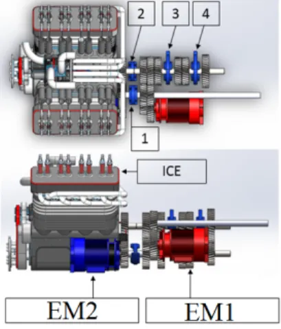
Additionally, a space-claiming CAD model was created as a preliminary assessment of the size and packaging feasibility for Design 2 as shown in Fig. 5 and Fig. 6.
3.4 Design 2 Schematic and Power Path-Flows As shown in Fig. 5, the speed-matching shifting sequence of the dual EM design is identical to the shifting sequence utilized in the single EM design. The most significant difference is that in the dual EM design, the ECU controls the combined speed
FIGURE 5. A conceptual transmission design for the dual EM solu-tion
FIGURE 6. A space-claiming model of the dual EM solution
of the ICE and EM2 and the speed of EM1 to speed-match gear sets. The following sections demonstrate the operational modes possible using this schematic.
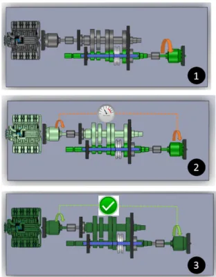
3.4.1 Power Path-Flows: Launching and reverse To launch the vehicle from complete stop, EM1 is used to drive the output shaft directly using the synchronizer 1 to activate the left-hand side gear mesh, as shown in Fig. 7. By inverting the motor phase, this same path-flow will serve for reversing.
3.4.2 Power Path-Flows: ICE Cranking and Speed-Matching As shown in Fig. 8, EM1 powers the ve-hicle, while the synchronizer is actuated to activate its right-hand side mesh. Thus, EM2 can start the ICE and assist it to reach the adequate angular speed to match the first gear ratio.
3.4.3 Power Path-Flows: Combined Power to Gears 1-4 Once the ICE angular speed-matches the proper gear ratio, synchronizers 3 and 4 will be electronically actuated to activate gears 1 through 4. While shifting to the upper gears,
FIGURE 7. Launching and reverse power path-flows for the dual EM solution
FIGURE 8. ICE cranking and speed-matching power path-flows for the dual EM solution
FIGURE 9. EM1 and ICE combined power for gear sets 1 through 4
EM1 will torque fill (or the ECU could cut-off fuel momentarily) the output shaft to unload the primary shaft and allow synchro-nizers 3 and 4 to switch to neutral, as the ICE RPM decays to match the next gear ratio. These path-flows are shown in Fig. 9.
3.4.4 Power Path-Flows: Combined Power to Gears 5-8 To use gears 5 through 8, synchronizer 2 must acti-vate the right-hand side mesh and actiacti-vate the multiplier gear set. Synchronizers 3 and 4 will operate the same way as in gears 1-4. These path-flows are shown in Fig. 10.
3.4.5 Power Path-Flows: Idle Charging With syn-chronizers 3 and 4 in their neutral positions and synchronizer 2 activating the right hand side mesh, the ICE can charge the
bat-FIGURE 10. Using the multiplier for gears 5 through 8
FIGURE 11. Using EM1 for regenerative braking
teries using EM2 as a generator.
3.4.6 Power Path-Flows: Regenerative Braking By having synchronizers 3 and 4 on their neutral position and synchronizer 1 activating the left-hand side mesh, EM1 could be used for regenerative braking. This is shown in Fig. 11
3.5 Speed-Matching Prototype
To validate Design 2, a prototype was constructed to demon-strate the concept of speed-matching gears to shift without a clutch. The prototype demonstrates that if an attempt is made to engage a gear set when the two gears are not speed-matched, the teeth on the gears will not mesh and grind against each other. Moreover, the prototype shows that by adjusting the speed of the EMs to speed-match the same two gears, it is easy to engage and disengage the gears without misalignment and grinding.
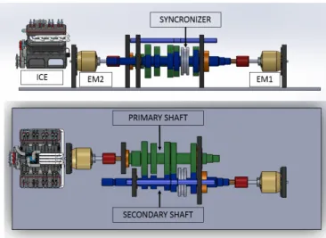
Actual transmission shafts, gears and synchronizers were mounted in a 3ft custom test bed, as shown in Fig. 12. Two brushless electric motors with three-phase speed controllers were installed to perform the functions of EM1 and EM2. A large servo was used to shift the synchronizer on the transmission shaft, and a servo controller and laptop were used to control the speed of the shafts and actuate the servo.
The physical prototype, shown in Fig. 13 was constructed out of aluminum and Delran and powered by two 22.2V lithium polymer batteries. Hall effect sensors and digital tachometers were added to display the frequency of rotation of each shaft in RPM.
FIGURE 12. A CAD model of the speed-matching prototype
FIGURE 13. The speed-matching prototype
4 Results
The physical prototype successfully demonstrated the speed-matching concept and its feasibility to enable a clutch-less transmission design. Speed-matched shifting can be achieved anywhere in the speed range by rotating EM1, calculating the target speed of EM2 based on the gear ratio of the gears being matched, raising the speed of EM2 to match that value, and ac-tuating the servo to mesh the gears. These steps are shown in Fig. 14. It is equally easy to start by rotating EM2, then calcu-lating the speed for EM1 and actuating the servo. This prototype demonstrates that by electronically controlling the rotational fre-quency of the transmission input and output shafts, the ECU can speed-match any two gears in the transmission to enable clutch-less shifting. While the prototype strove for zero-speed differ-ence gear matching, a more involved solution is required to allow for seamless engagement and disengagement of gears to mini-mize the perceptibility of ratio changes under rapid acceleration or deceleration. In such a case, a zero-torque shift is preferable to a zero-speed difference shift, as the impulse imparted by the
FIGURE 14. 1. EM1 rotates to power the output shaft. 2. EM2 simultaneously cranks the ICE and increases its angular speed. 3. When the precise speed ratio is achieved, first gear is engaged
shift is reduced, especially when disengaging a coupled gear set. Continued work aims to implement such a solution, making use of shaft torque sensors or other similar devices. Torque would be measured and filtered via a form of state estimation to deter-mine the zero cross point of the two gears, the point at which a calculated interface torque transitions to a torque in the oppo-site direction (a negative torque). At the exact moment where the torque crosses the zero value, the shift would take place. Be-cause the gears are unloaded at this point, the shift is smooth and changing gears does not significantly load any components, extending transmission service life.
5 Conclusion
We have demonstrated a significant reduction in transmis-sion mass by removing the clutch along with several gears. A prototype of this reduced mass transmission successfully demon-strated the clutch-less shifting concept, while power flow dia-grams showed that a full range of operating modes (launch, re-verse, charge, cruise) is feasible. We further calculated the po-tential increase in efficiency and reduction of inertial losses by removing the clutch and showed torque-filling capabilities to as-sist shifting after removing gears.
5.1 Future Work
Looking forward, we plan to upgrade the mock-up to use the clients gears, synchronizers, and ICE. This will allow us to perform a full-scale drivetrain stress test on a dynamometer or test chassis. Areas of interest include whether the clutch-less shifting will increase wear to the synchronizers, simplifications to the synchronizers design, and the accuracy of engine control and instrumentation.
ACKNOWLEDGMENT
We would like to thank Amos Winter, Dan Dorsch, Michael Buchman, and the client team for supporting the team with re-sources, encouragement, and active discussions. Additionally, we would like to acknowledge the support provided by Ferrari, who was a sponsor of the team through MIT’s Global Engineer-ing course.
REFERENCES
[1] Milman, O., 2013. “Carbon emissions must be cut signif-icantly by 2020, says UN report”. United Nations Univer-sity/The Guardian.
[2] Office of Transportation and Air Quality, 2014. Regulations and standards, April. See also URL http://wiki.ece.cmu.edu/ddl/index.php. [3] How hybrid cars and trucks work. See also URL
http://www.ucsusa.org/clean_vehicles. [4] Chu, S., and Majumdar, A., 2012. “Opportunities and
chal-lenges for a sustainable energy future”. Nature, 488(7411), August, pp. 294–303.
[5] University of Chicago. Autonomie (driving cycle simula-tion software, version rev13).
[6] Wikipedia, 2015. Ferrari 458 — Wikipedia,
the free encyclopedia. See also URL
en.wikipedia.org/wiki/Ferrari_458.
[7] Ehsani, M., Gao, Y., Gay, S., and Emadi, A., 2005. Mod-ern Electric Hybrid Electric, and Fuel Cell Vehicles. CRC Press, Boca Raton, Florida.
[8] Ravey, A. “Design and control strategy of powertrain in hybrid electric vehicles”. PhD thesis, Universite de Tech-nologie de Belfort-Montbeliard.
[9] Asaei, B., and Habibidoost, M., 2012. “Design, simula-tion, and prototype production of a through the road par-allel hybrid electric motorcycle”. Energy Conversion and Management,71, July, pp. 12–20.
[10] Galvagno, E., Morina, D., Sorniotti, A., and Velardoc-chia, M., 2013. “Drivability analysis of through-the-road-parallel hybrid vehicles”. Meccanica, 48, March, pp. 351– 366.
[11] Meisel, J., Shabbir, W., and Evangelou, S., 2013. “Eval-uation of the through-the-road architecture for plug-in
hy-brid electric vehicle powertrains”. Electrical Vehicle Con-ference, October, pp. 1–5.
[12] Office of Energy Efficiency Natural Resources Canada, 2013. Energy efficiency in buildings, May. See also URL wiki.ece.cmu.edu/ddl/index.php.
[13] Magee, C., 2014. 2014 Ferrari LaFerrari, July. See also URL www.caranddriver.com/ferrari/ laferrari.
[14] Pund, D., 2014. 2014 McLaren p1, July. See also URL www.caranddriver.com/mclaren/p1.
[15] Gall, J., 2013. 2015 Porsche 918 Spyder, December. See also URL www.caranddriver.com/porsche/918. [16] Wang, J., Wang, X., Ma, Y., Liu, N., and Yang, Z., 2014. “Analysis of heat transfer in power split device for hybrid electric vehicle using thermal network method”. Advances in Mechanical Engineering, January.
[17] Wei, Z., and Guo, X., 2014. “Analysis and modeling of transmission efficiency of vehicle driveline”. SAE Interna-tional, January.
[18] Zhou, X., Walker., P., and Zhang, N., 2014. “A study of power losses in a two-speed dual clutch transmission”. SAE International, January.
[19] Fajri, P., Ahmadi, R., and Ferdowsi, M., 2012. “Equivalent vehicle rotational inertia used for electric vehicle test bench dynamic studies”. IEEE.
[20] Krein, P., Roethemeyer, T., White, R., and Masterson, B., 1994. “Packaging and performance of an IGBT-based hy-brid electric vehicle”. Power Electronics in Transportation, pp. 47–52.
[21] Farrington, R., and Rugh, J., 2000. “Impact of vehicle air conditioning on fuel economy, tailpipe emissions, and elec-tric vehicle range”. Earth Technologies Forum, October.
[22] Power steering calculations. See also URL
http://www.brevini.co.nz/wp-content/ uploads/calculators/PowerSteeringCalc .pdfns.
[23] U.S. Energy Information Administration, 2012., December.
Appendix A: Ferrari 458 Transmission Versus Pro-posed Design Weight Savings Estimate
The proposed transmission design removes several parts of the existing transmission to cut mass. Here, first-order weight estimates are made, using size approximations and the density of steel, ρ = 8.0cmg3
.1 Shaft
Dimensions of the transmission shaft are assumed to be: 1. Diameter = 30mm
2. Length = 400mm
The mass can be calculated as:
m= ρπ(d 2) 2l = (8.0 g cm3)π(15mm) 2(400mm) = 2.26kg .2 Gear
Dimensions of the gear is assumed to be: 1. Outer diameter = 100mm
2. Inner diameter = 30mm 3. Length = 25mm
The mass can be calculated as:
m= ((d0 2) 2− (di 2) 2)l = (8.0 g cm3)π((50mm) 2− (15mm)2)(25mm) = 1.43kg .3 Synchronizers
Dimensions of the synchronizers are assumed to be: 1. Outer diameter = 120mm
2. Inner diameter = 100mm 3. Length = 12mm
The mass can be calculated as:
m= ((d0 2) 2− (di 2) 2)l = (8.0 g cm3)π((60mm) 2− (55mm)2)(15mm) = 0.322kg .4 Clutch
Dimensions of the synchronizer are assumed to be: 1. Diameter = 175mm
2. Length = 12mm
The mass can be calculated as:
m= ρπ(d 2) 2l = (8.0 g cm3)π(175mm) 2(15mm) = 11.5kg
Appendix B: Accessory Drive
Three ways to power the accessory drive were considered: 1. One traction motor:
The traction motor will certainly have the power to run the starter/accessory drive, but to start/stop the engine the trac-tion motor must be clutched creatively. Output modules will be driven at variable speeds (inefficiently) or constant speed (adding cost and complexity of a governor along with addi-tional rotating inertia, e.g. revolving door governor model). The electric motor must constantly be running to support ac-cessory drive (e.g. power steering, which cannot be turned off at low speeds).
2. One traction motor/starter, one accessory drive motor: This has the potential for reduced volume and a lower center of gravity, but requires two boxes to locate instead of one. 3. One traction motor, one accessory drive/starter motor:
This has the same benefits/challenges as 2.
.5 Starter Size Estimation
To estimate the size of the starter engine, we assumed a mo-tor starting speed of 250RPM. For a standard 4 cylinder, 2L engine in a commercial economy car, there is approximately 240Nm of static friction and 80Nm to maintain cranking speed, assuming the stalled torque is 3x cranking torque. The econ-omy car displaces 0.5L/cylinder, while a high-performance car displaces 0.56L per cylinder.
One can use the ratio of the performance car’s displacement volume, vper f, to the economy car’s displacement to determine:
rper f=
r vper f
vecon
r2
econ (4)
We assume that the static friction scales with the surface area (SA) contacting the piston.
SAper f SAecon =2πrper fh 2πreconh =rper f recon (5)
These two equations reduce to:
SAper f SAecon = q.56L/cylinder .5L/cylinderrecon2 recon = p 1.125r2 econ recon (6)
and SAFerrari= 1.06 · SAecon
TABLE 3. Assumptions to calculate power needed for air condition-ing [21] • Ambient temperature: 323K • In-car temperature: 295K • Driving speed: 25 m/s • Air density at 323K: 1.1 kg/m3 • Air density at 295K: 1.3 kg/m3 • Solar loading: 900 W m2
• Car window area: 3.5 m2
The target turnover torque is 240Nm · 1.06 = 255Nm to counter static friction and 84.9Nm of cranking speed. assum-ing a common reduction of 10:1 from the pinion and rassum-ing, the motor torque is 25.5Nm while stalled and 8.5Nm while driving at ω = 2πRPM60s = 260.2rads . Using the relation P = τω, we can calculate the starter motor power:
P= τω = (8.5Nm)(260.2rad
s ) = 2230W (7)
.6 Air Conditioner Motor
At most, 50% of the window will be exposed to the sun at once, if the sun is at an angle. Peak solar load is:
1.75m2cos(30°)900W
m2 = 1.36kW (8)
Assuming that the coefficient of body conductance at 25 m/s is approximately 80WK, then body conductance can be calculated as:
80W
K(323 − 295) = 1.44kW (9)
To find the heat conducted through a 6mm glass window that conducts as 1.4 mKW :
Q=kwA∆T
t =
1.4mKW 3.5m218K
6mm = 14.7kW (10)
Summing the three calculated heats, we find that total heat-ing is 17.5kW. In Carnot case, one can use:
TABLE 4. Assumptions to calculate the torque requirements for power steering [22]
• τ: kingpin torque (in Nm) • W: Vehicle weight on axle, 680kg
• µ: Coefficient of friction between tires and road, 0.9 • B: tire width, .24m • E: kingpin offset, .13m Cp= QH W = TH TH− TC (11) Rearranging for W: W=QH Cp =Qlost− Qgenerated 3.5 = 17.5kW 3.5 = 5kW (12)
.7 Power Steering Pump Sizing
Assuming the worst-case stationary steering condition [22], one can calculate torque as:
τ = W µ r
B2
8 + E
2 (13)
Using these values, τ = 916Nm . For a steering ratio of 12:1 that requires two turns from lock to lock:
α =720° 12 = 60.5° → ω = α t = 60.5° 1s = 1.06 rad s (14) P= τω = 917Nm1.06 1s = 969W (15)
.8 Minimum Accessory Drive Size
With total loading, the accessory drive must supply Psize= max(PAC, Pstart) + Psteer
≈ max(5kW, 2.2kW ) + 1kW = 6kW
FIGURE 15. A plot comparing full-load efficiencies for a range of motor powers [23]
![TABLE 1. The final list of design targets to match or improve upon for a high-performance hybrid transmission [6]](https://thumb-eu.123doks.com/thumbv2/123doknet/14683789.559776/5.918.84.408.109.362/table-final-design-targets-improve-performance-hybrid-transmission.webp)
![TABLE 3. Assumptions to calculate power needed for air condition- condition-ing [21] • Ambient temperature: 323K • In-car temperature: 295K • Driving speed: 25 m/s • Air density at 323K: 1.1 kg/m 3 • Air density at 295K: 1.3 kg/m 3 • Solar loading: 900 W m](https://thumb-eu.123doks.com/thumbv2/123doknet/14683789.559776/15.918.549.802.180.373/assumptions-calculate-condition-condition-ambient-temperature-temperature-driving.webp)
![TABLE 4. Assumptions to calculate the torque requirements for power steering [22]](https://thumb-eu.123doks.com/thumbv2/123doknet/14683789.559776/16.918.53.446.169.572/table-assumptions-calculate-torque-requirements-power-steering.webp)
