Publisher’s version / Version de l'éditeur: Technical Report, 2013-02-06
READ THESE TERMS AND CONDITIONS CAREFULLY BEFORE USING THIS WEBSITE.
https://nrc-publications.canada.ca/eng/copyright
Vous avez des questions? Nous pouvons vous aider. Pour communiquer directement avec un auteur, consultez la
première page de la revue dans laquelle son article a été publié afin de trouver ses coordonnées. Si vous n’arrivez
Questions? Contact the NRC Publications Archive team at
PublicationsArchive-ArchivesPublications@nrc-cnrc.gc.ca. If you wish to email the authors directly, please see the first page of the publication for their contact information.
NRC Publications Archive
Archives des publications du CNRC
For the publisher’s version, please access the DOI link below./ Pour consulter la version de l’éditeur, utilisez le lien DOI ci-dessous.
https://doi.org/10.4224/21270174
Access and use of this website and the material on it are subject to the Terms and Conditions set forth at
Second order waves before and after the floor work in the OEB in 2010 : Part B
Zaman, Hasanat; McKay, Shane; NRC Ocean, Coastal and River Engineering
https://publications-cnrc.canada.ca/fra/droits
L’accès à ce site Web et l’utilisation de son contenu sont assujettis aux conditions présentées dans le site LISEZ CES CONDITIONS ATTENTIVEMENT AVANT D’UTILISER CE SITE WEB.
NRC Publications Record / Notice d'Archives des publications de CNRC:
https://nrc-publications.canada.ca/eng/view/object/?id=900a3d0d-b1ee-427d-a6d5-18b35dd9c751 https://publications-cnrc.canada.ca/fra/voir/objet/?id=900a3d0d-b1ee-427d-a6d5-18b35dd9c751
OCRE-TR-2013-004
NATIONAL RESEARCH COUNCIL CANADA OCEAN, COASTAL AND RIVER ENGINEERING
Second order waves before and after
the floor work in the OEB in 2010:
Part B
Technical Report - UNCLASSIFIED
Hasanat Zaman Shane McKay February, 2013
REPORT NUMBER PROJECT NUMBER
DATE
SECURITY CLASSIFICATION DISTRIBUTION
TITLE
AUTHOR(S)
CORPORATE AUTHOR(S)/PERFORMING AGENCY(S) PUBLICATION (Journal or Conference name)
SPONSORING AGENCY(S)
RAW DATA STORAGE LOCATION(S)
PEER REVIEWED
MODEL # PROP
EMBARGO PERIOD
PROJECT (NPArC) GROUP (NPArC)
PROGRAM (NPArC) FACILITY (NPArC)
KEY WORDS PAGES TABLES FIGS.
SUMMARY
Report Documentation Page
OCRE - GOCF
2013 6 February
Wave quality, 2nd order waves, unwanted free waves i, 132, App 1-2 2
OCRE-TR-2013-004 PJ2414-26 UNCLASSIFIED UNLIMITED
Second order waves before and after the floor work in the OEB in 2010: Part B
Hasanat Zaman and Shane McKay
NRC Ocean, Coastal and River Engineering
NRC-ST. JOHN’S
--- --- Research
--- St. John's: P.O. Box 12093, Arctic Ave, St. John's, NL A1B 3T5
This is a continuation of the work reported in TR-2013-003. In summer 2010, the south-west side trenches (0.3m x 0.4m) under and in front of the wave makers in the OEB have been permanently filled-up to provide a homogeneous bottom and uniform water depth all over the basin. This work is to understand the improvement of the wave quality after the floor work. Two sets of
experimental data comprised of mono- and bi-chromatic waves before and after the floor work are used to identify the impact of the development work on the generation of unwanted second order free waves in the OEB. In this report results are compared between the measured energies at different probe locations and also second order wave components before and after the floor work in the OEB. Comparisons are shown in terms of measured wave energies, primary waves, bounded waves and unwanted second order free waves elevations. In this report 0.8m of water depth is considered. In most of the cases it is observed from the results that the shallower the wave the better the wave quality after the floor work.
National Research Council Conseil national de recherches Canada Canada Ocean, Coastal and River Génie océanique, côtier et fluvial Engineering
Second order waves before and after the floor work in the OEB in
2010: Part B
Technical Report UNCLASSIFIED
OCRE-TR-2013-004
Hasanat Zaman and Shane McKay
OCRE-TR-2013-004 i
TABLE OF CONTENTS
Page NoABSTRACT ...1
1. INCIDENT WAVE CONDITIONS ...1
2. DATA ANALYSES...2
2.1 COMPARISONS - 1: Monochromatic waves ... 2
2.2 COMPARISONS - 2: Bichromatic waves ...2
3. LWAVE utilization ...3
4. RESULTS ...3
5. CONCLUSIONS...3
REFERENCES ...3
Appendix-I Compares energy distribution and second order wave components for mono-chromatic wave over 0.8m water depth at different probe locations. ...5
Appendix-II Compares energy distribution and second order wave components for bi-chromatic wave over 0.8m water depth at different probe locations. ... 48
OCRE-TR-2013-004 1
ABSTRACT
This is a continuation of the work reported in OCRE-TR-2013-003 (Second order waves before and after the floor work in the OEB in 2010: Part-A). In summer 2010, the south-west side trenches (width 0.4m and depth 0.3m) under and in front of the wave makers in the OEB have been permanently filled-up to provide a homogeneous bottom and uniform water depth all over the basin. This work is to understand the improvement of the wave quality after the floor work. In this work two sets of experimental data comprised of mono- and bi-chromatic waves before and after the floor work are used to identify the impact of the development work on the generation of unwanted second order free waves in the OEB. The first set of wave data (called before from now on) was obtained from the experimental work before the trenches were filled-up and the second set of data (called after from now on) was obtained from the experiment after the trenches were filled up. In the experiments both mono- and bi-chromatic wave are considered for 0.8m water depths. Results for 0.8m water depth are reported in this report (Part-B). Results for 0.4m, 0.5m and 0.6m water depth were reported in Part-A. Comparisons of the data were done for identical wave conditions.
Please refer to report “Second order waves before and after the floor work in the OEB
in 2010: Part-A” for description of the experiments, experimental setup, data acquisition
etc..
1. INCIDENT WAVE CONDITIONS
In the experiments both mono- and bi-chromatic waves of different wave periods, wave heights and water depths are used. See Zaman and Mak (2007) and Zaman et al (2010) for several cases of mono- and bi-chromatic waves before the floor work and Zaman et al (2011) and Zaman et al (2013) after the floor work. Tables 2a and 2b show different incident wave conditions that we used in the experiments. In the tables below T1
and T2 are wave periods, H1 and H2 are the wave heights, h is the water depth, L is the
wave length and h/L is the relative water depth.
Table 2a Mono-chromatic incident wave parameters (h=0.8m) T1 (s) H1 (m) h(m) h/L
M8-1 2.370 0.06 0.8 0.133 M8-2 3.035 0.08 0.8 0.100 M8-3 4.105 0.06 0.8 0.071 Table 2b Bi-chromatic incident wave parameters (h=0.8m) T1 (s) h(m) H1 (m) T2 (s) H2 (m) h/L
B8-1 1.00 0.8 0.06 0.90 0.06 0.516 B8-2 1.55 0.8 0.02 1.45 0.02 0.236 B8-3 1.55 0.8 0.08 1.45 0.08 0.236 B8-4 2.12 0.8 0.08 2.02 0.08 0.153
2 OCRE-TR-2013-004
The bottom of the basin was flat and the blanking plates were deployed to cover the north beach.
2. DATA ANALYSES
We have analyzed two sets of data, one for before the floor work and the other one is
after the floor work. Different wave conditions and water depths are considered as shown in Tables 2a and 2b. All the data are compared and the results are shown in terms of surface elevations and wave energies across the wave tank at probes 5-4-3-6-7 (Probe-5, Probe-4, Probe-3, Probe-6 and Probe-7) and along the tank at probes 1-2-3-8-9 (Probe-1, Probe-2, Probe-3, Probe-8 and Probe-9), see Fig. 1. Data at Probes 10, 11, 12, 13 and 14 are not available for 0.8m water depth.
2.1 COMPARISONS - 1: Monochromatic waves
Tables 2a and 2b respectively, show the incident wave conditions for mono-chromatic waves, respectively over 0.8m (M8) water depths. All the above cases are run with and without trenches condition in front of the south and west wave makers of the OEB. Comparisons of the results are made between both cases, with and without trenches. Results are compared in terms of measured surface elevation data, wave energies and isolated wave components including second order waves across and along the wave tank. Figs. 2a to 7j show the energy distribution, measured surface elevation, isolated primary wave, bounded and second order unwanted free wave components at different probe locations in the basin for the mono-chromatic waves of 0.8m water depth mentioned in Table 2a. Measured water surface elevations, wave energies and isolated primary, bounded and unwanted free waves at across-tank probes 5-4-3-6-7 and at the along-tank probes 1-2-3-8-9 are plotted together to show the differences in the amplitudes after and before the floor work. Unwanted free waves are reproduced due to the mismatch of the boundary conditions at the wave paddle and due to the displacement of the wave paddle from its zero position.
It is observed from the results that the smaller the relative water depth h L (i.e.
shallower the wave) the better the wave quality after the floor work. For shallower wave it is also noted that the shallower the wave the better the wave energies distributions across the tank for measured, primary, bounded and free waves for after cases. It is perceived that the second order wave components are reduced for shallow waves after the floor work.
2.2 COMPARISONS - 2: Bichromatic waves
Table 2b show the incident wave conditions for bi-chromatic waves over 0.8m (B8) water depths. The above cases are run for: with and without trenches conditions in front of the south and west wave makers of the OEB. Results are again compared between both
OCRE-TR-2013-004 3
elevation data, wave energies and isolated wave components including second order waves across the wave tank.
Figs. 8a to 19j show the energy distribution, measured surface elevation, isolated primary wave, bounded and second order unwanted free wave components at different probe locations in the basin for the bi-chromatic waves of 0.8m water depth for different incident wave conditions shown in Table 2b. Obtained water surface elevations, wave energies and isolated primary, bounded and unwanted free waves at across-tank probes 5-4-3-6-7 and at the along-tank probes 1-2-3-8-9 are plotted together to show the differences in the component amplitudes after and before the floor work.
3. LWAVE utilization
A NRC-IOT computer code LWAVE that can split a measured surface elevation data set into its component waves is used for the analysis. This code is utilized to isolate the primary waves, bounded second order waves and unwanted free waves from the raw measured data at every probe location.
4. RESULTS
In this experiment 0.8m water depths (h= 0.8m) was used. The incident wave parameters are shown in Table 2a for mono- and Table 2b for bi-chromatic waves.
Results are compared between the measured wave data, before and after the floor work in OEB.
Appendix-I compares energy distribution and second order wave components for mono-chromatic wave over 0.8m water depth at different probe locations.
Appendix-II compares energy distribution and second order wave components for bi-chromatic wave over 0.8m water depth at different probe locations.
5. CONCLUSIONS
Comparisons of the results for surface elevations and energy propagations between the measured data before and after the floor work are shown. Deep water wave (h Lt0.5)
will not be affected by the floor and the wave starts to feel the bottom when the relative water depth (h L) is less than 0.5. So the smaller the value of h Lmeans more the
effects of the bottom on the propagating waves. From the data it is observed that after the floor work, the wave quality in the tank improved for the shallow water where the floor effect is essentially an important issue. For intermediate and deep water case this change or improvement is insignificant.
4 OCRE-TR-2013-004
John’s.
Zaman, M. H., Baddour, E. and Mckay, S. (2011): Wave propagation before and after the floor work in the OEB in 2010, TR-2011-16, March, National Research Council Canada, Institute for Ocean Technology.
Zaman, M. H., Peng, H., Baddour, E., Spencer, D. and Mckay, S. (2010): Identifications of spurious waves in the wave tank with shallow water, 29th Int. Conf. on offshore Mech. and Arctic Eng. (OMAE-2010), American Society of Mechanical Engineers (ASME), Shanghai, China, on CD-ROM.
Zaman, M. H. and L. Mak (2007): Second order wave generation technique in the laboratory, 26th Int. Conf. on offshore Mech. and Arctic Eng. (OMAE-2007), American Society of Mechanical Engineers (ASME), San Diego, USA, on CD-ROM.
OCRE-TR-2013-004 5
Appendix – I
Energy distribution and second order wave components for monochromatic wave over 0.8m water depth
Probes array: Probes: 1-2-3-8-9 Probes: 5-4-3-6-7
6 OCRE-TR-2013-004
Fig. 2a: Comparisons between primary and low frequency wave energy Probes: 1-2-3-8-9
OCRE-TR-2013-004 7
Fig. 2b: Comparisons between high frequency wave energy Probes: 1-2-3-8-9
8 OCRE-TR-2013-004
Fig. 2c: Comparisons between primary and low frequency wave energy Probes: 5-4-3-6-7
OCRE-TR-2013-004 9
Fig. 2d: Comparisons between high frequency wave energy Probes: 5-4-3-6-7
10 OCRE-TR-2013-004
Fig. 3a: Isolated wave components from measured wave data at Probe-1 M8-1 : REGP8_H0P06_T2P370
OCRE-TR-2013-004 11
12 OCRE-TR-2013-004
Fig. 3c: Isolated wave components from measured wave data at Probe-3 M8-1 : REGP8_H0P06_T2P370
OCRE-TR-2013-004 13
14 OCRE-TR-2013-004
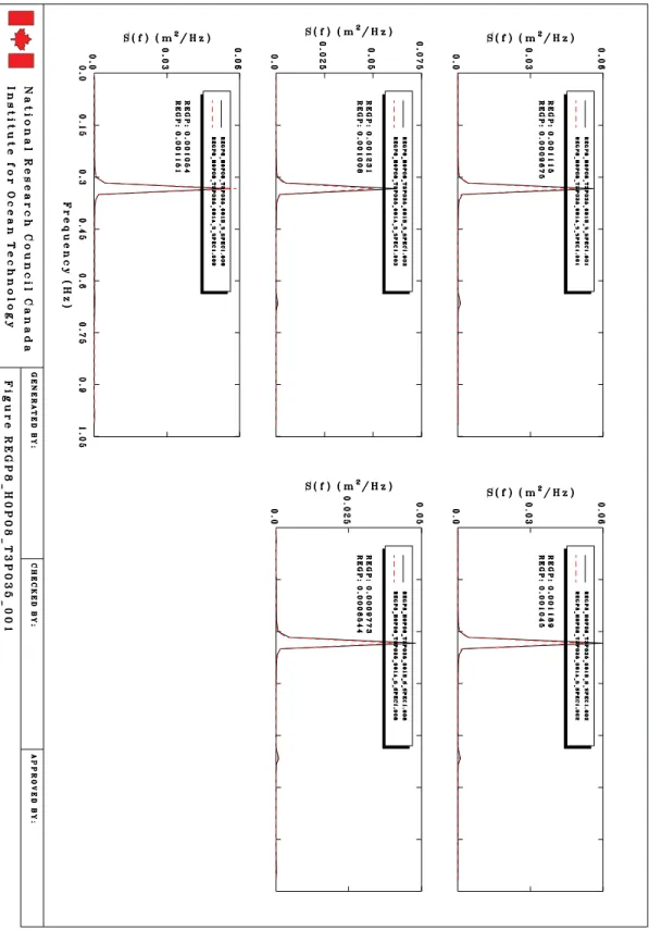
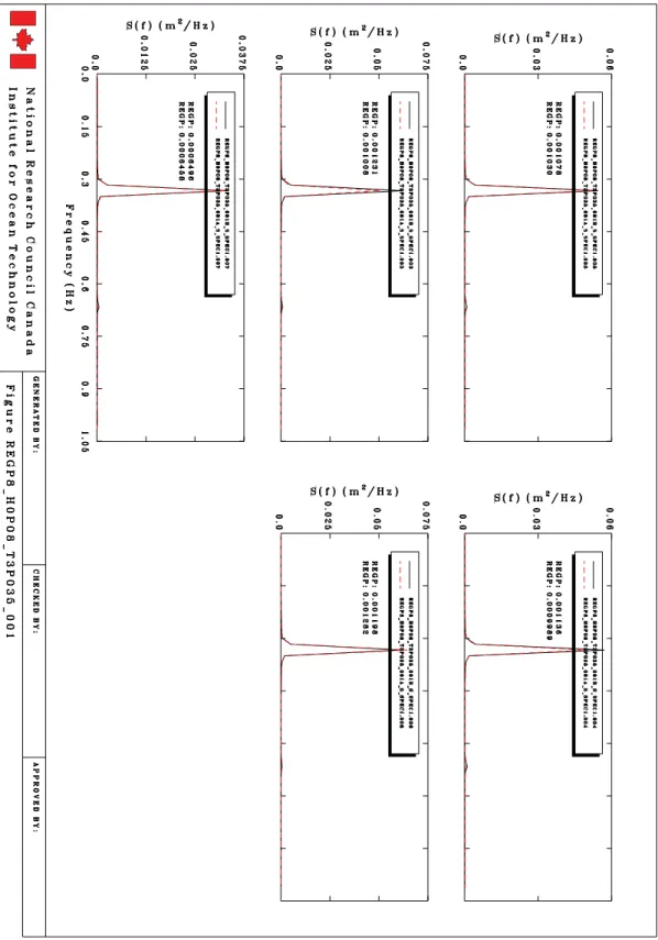
Fig. 3e: Isolated wave components from measured wave data at Probe-5 M8-1 : REGP8_H0P06_T2P370
OCRE-TR-2013-004 15
16 OCRE-TR-2013-004
Fig. 3g: Isolated wave components from measured wave data at Probe-7 M8-1 : REGP8_H0P06_T2P370
OCRE-TR-2013-004 17
18 OCRE-TR-2013-004
Fig. 3i: Isolated wave components from measured wave data at Probe-9 M8-1 : REGP8_H0P06_T2P370
OCRE-TR-2013-004 19
20 OCRE-TR-2013-004
Fig. 4a: Comparisons between primary and low frequency wave energy Probes: 1-2-3-8-9
OCRE-TR-2013-004 21
Fig. 4b: Comparisons between high frequency wave energy Probes: 1-2-3-8-9
22 OCRE-TR-2013-004
Fig. 4c: Comparisons between primary and low frequency wave energy Probes: 5-4-3-6-7
OCRE-TR-2013-004 23
Fig. 4d: Comparisons between high frequency wave energy Probes: 5-4-3-6-7
24 OCRE-TR-2013-004
Fig. 5a: Isolated wave components from measured wave data at Probe-1 B8-2 : REGP8_H0P08_T3P035
OCRE-TR-2013-004 25
26 OCRE-TR-2013-004
Fig. 5c: Isolated wave components from measured wave data at Probe-3 B8-2 : REGP8_H0P08_T3P035
OCRE-TR-2013-004 27
28 OCRE-TR-2013-004
Fig. 5e: Isolated wave components from measured wave data at Probe-5 B8-2 : REGP8_H0P08_T3P035
OCRE-TR-2013-004 29
30 OCRE-TR-2013-004
Fig. 5g: Isolated wave components from measured wave data at Probe-7 B8-2 : REGP8_H0P08_T3P035
OCRE-TR-2013-004 31
32 OCRE-TR-2013-004
Fig. 5i: Isolated wave components from measured wave data at Probe-9 B8-2 : REGP8_H0P08_T3P035
OCRE-TR-2013-004 33
34 OCRE-TR-2013-004
Fig. 6a: Comparisons between primary and low frequency wave energy Probes: 1-2-3-8-9
OCRE-TR-2013-004 35
Fig. 6b: Comparisons between high frequency wave energy Probes: 1-2-3-8-9
36 OCRE-TR-2013-004
Fig. 6c: Comparisons between primary and low frequency wave energy Probes: 5-4-3-6-7
OCRE-TR-2013-004 37
Fig. 6d: Comparisons between high frequency wave energy Probes: 5-4-3-6-7
38 OCRE-TR-2013-004
Fig. 7a: Isolated wave components from measured wave data at Probe-1 B8-3 : REGP8_H0P08_T4P105
OCRE-TR-2013-004 39
40 OCRE-TR-2013-004
Fig. 7c: Isolated wave components from measured wave data at Probe-3 B8-3 : REGP8_H0P08_T4P105
OCRE-TR-2013-004 41
42 OCRE-TR-2013-004
Fig. 7e: Isolated wave components from measured wave data at Probe-5 B8-3 : REGP8_H0P08_T4P105
OCRE-TR-2013-004 43
44 OCRE-TR-2013-004
Fig. 7g: Isolated wave components from measured wave data at Probe-7 B8-3 : REGP8_H0P08_T4P105
OCRE-TR-2013-004 45
46 OCRE-TR-2013-004
Fig. 7i: Isolated wave components from measured wave data at Probe-9 B8-3 : REGP8_H0P08_T4P105
OCRE-TR-2013-004 47
48 OCRE-TR-2013-004
Appendix – II
Energy distribution and second order wave components for bichromatic wave over 0.8m water depth
Probes array: Probes: 1-2-3-8-9 Probes: 5-4-3-6-7
OCRE-TR-2013-004 49
Fig. 8a: Comparisons between primary and low frequency wave energy Probes: 1-2-3-8-9
50 OCRE-TR-2013-004
Fig. 8b: Comparisons between high frequency wave energy Probes: 1-2-3-8-9
OCRE-TR-2013-004 51
Fig. 8c: Comparisons between primary and low frequency wave energy Probes: 5-4-3-6-7
52 OCRE-TR-2013-004
Fig. 8d: Comparisons between high frequency wave energy Probes: 5-4-3-6-7
OCRE-TR-2013-004 53
54 OCRE-TR-2013-004
Fig. 9b: Isolated wave components from measured wave data at Probe-2 B8-1 : BIP8_H0P06_T1P0_T0P9
OCRE-TR-2013-004 55
56 OCRE-TR-2013-004
Fig. 9d: Isolated wave components from measured wave data at Probe-4 B8-1 : BIP8_H0P06_T1P0_T0P9
OCRE-TR-2013-004 57
58 OCRE-TR-2013-004
Fig. 9f: Isolated wave components from measured wave data at Probe-6 B8-1 : BIP8_H0P06_T1P0_T0P9
OCRE-TR-2013-004 59
60 OCRE-TR-2013-004
Fig. 9h: Isolated wave components from measured wave data at Probe-8 B8-1 : BIP8_H0P06_T1P0_T0P9
OCRE-TR-2013-004 61
62 OCRE-TR-2013-004
Fig. 9j: Isolated wave components from measured wave data at Probe-10 B8-1 : BIP8_H0P06_T1P0_T0P9
OCRE-TR-2013-004 63
Fig. 10a: Comparisons between primary and low frequency wave energy Probes: 1-2-3-8-9
64 OCRE-TR-2013-004
Fig. 10b: Comparisons between high frequency wave energy Probes: 1-2-3-8-9
OCRE-TR-2013-004 65
66 OCRE-TR-2013-004
Fig. 10d: Comparisons between high frequency wave energy Probes: 5-4-3-6-7
OCRE-TR-2013-004 67
68 OCRE-TR-2013-004
Fig. 11b: Isolated wave components from measured wave data at Probe-2 B8-2 : BIP8_H0P02_T1P55_T1P45
OCRE-TR-2013-004 69
70 OCRE-TR-2013-004
Fig. 11d: Isolated wave components from measured wave data at Probe-4 B8-2 : BIP8_H0P02_T1P55_T1P45
OCRE-TR-2013-004 71
72 OCRE-TR-2013-004
Fig. 11f: Isolated wave components from measured wave data at Probe-6 B8-2 : BIP8_H0P02_T1P55_T1P45
OCRE-TR-2013-004 73
74 OCRE-TR-2013-004
Fig. 11h: Isolated wave components from measured wave data at Probe-8 B8-2 : BIP8_H0P02_T1P55_T1P45
OCRE-TR-2013-004 75
76 OCRE-TR-2013-004
Fig. 11j: Isolated wave components from measured wave data at Probe-10 B8-2 : BIP8_H0P02_T1P55_T1P45
OCRE-TR-2013-004 77
Fig. 12a: Comparisons between primary and low frequency wave energy Probes: 1-2-3-8-9
78 OCRE-TR-2013-004
Fig. 12b: Comparisons between high frequency wave energy Probes: 1-2-3-8-9
OCRE-TR-2013-004 79
Fig. 12c: Comparisons between primary and low frequency wave energy Probes: 5-4-3-6-7
80 OCRE-TR-2013-004
Fig. 12d: Comparisons between high frequency wave energy Probes: 5-4-3-6-7
OCRE-TR-2013-004 81
82 OCRE-TR-2013-004
Fig. 13b: Isolated wave components from measured wave data at Probe-2 B8-3 : BIP8_H0P08_T1P55_T1P45
OCRE-TR-2013-004 83
84 OCRE-TR-2013-004
Fig. 13d: Isolated wave components from measured wave data at Probe-4 B8-3 : BIP8_H0P08_T1P55_T1P45
OCRE-TR-2013-004 85
86 OCRE-TR-2013-004
Fig. 13f: Isolated wave components from measured wave data at Probe-6 B8-3 : BIP8_H0P08_T1P55_T1P45
OCRE-TR-2013-004 87
88 OCRE-TR-2013-004
Fig. 13h: Isolated wave components from measured wave data at Probe-8 B8-3 : BIP8_H0P08_T1P55_T1P45
OCRE-TR-2013-004 89
90 OCRE-TR-2013-004
Fig. 13j: Isolated wave components from measured wave data at Probe-10 B8-3 : BIP8_H0P08_T1P55_T1P45
OCRE-TR-2013-004 91
Fig. 14a: Comparisons between primary and low frequency wave energy Probes: 1-2-3-8-9
92 OCRE-TR-2013-004
Fig. 14b: Comparisons between high frequency wave energy Probes: 1-2-3-8-9
OCRE-TR-2013-004 93
Fig. 14c: Comparisons between primary and low frequency wave energy Probes: 5-4-3-6-7
94 OCRE-TR-2013-004
Fig. 14d: Comparisons between high frequency wave energy Probes: 5-4-3-6-7
OCRE-TR-2013-004 95
96 OCRE-TR-2013-004
Fig. 15b: Isolated wave components from measured wave data at Probe-2 B8-4 : BIP8_H0P06_T2P12_T2P02
OCRE-TR-2013-004 97
98 OCRE-TR-2013-004
Fig. 15d: Isolated wave components from measured wave data at Probe-4 B8-4 : BIP8_H0P06_T2P12_T2P02
OCRE-TR-2013-004 99
100 OCRE-TR-2013-004
Fig. 15f: Isolated wave components from measured wave data at Probe-6 B8-4 : BIP8_H0P06_T2P12_T2P02
OCRE-TR-2013-004 101
102 OCRE-TR-2013-004
Fig. 15h: Isolated wave components from measured wave data at Probe-8 B8-4 : BIP8_H0P06_T2P12_T2P02
OCRE-TR-2013-004 103
104 OCRE-TR-2013-004
Fig. 15j: Isolated wave components from measured wave data at Probe-10 B8-4 : BIP8_H0P06_T2P12_T2P02
OCRE-TR-2013-004 105
Fig. 16a: Comparisons between primary and low frequency wave energy Probes: 1-2-3-8-9
106 OCRE-TR-2013-004
Fig. 16b: Comparisons between high frequency wave energy Probes: 1-2-3-8-9
OCRE-TR-2013-004 107
Fig. 16c: Comparisons between primary and low frequency wave energy Probes: 5-4-3-6-7
108 OCRE-TR-2013-004
Fig. 16d: Comparisons between high frequency wave energy Probes: 5-4-3-6-7
OCRE-TR-2013-004 109
110 OCRE-TR-2013-004
Fig. 17b: Isolated wave components from measured wave data at Probe-2 B8-5 : BIP8_H0P08_T2P22_T2P0
OCRE-TR-2013-004 111
112 OCRE-TR-2013-004
Fig. 17d: Isolated wave components from measured wave data at Probe-4 B8-5 : BIP8_H0P08_T2P22_T2P0
OCRE-TR-2013-004 113
114 OCRE-TR-2013-004
Fig. 17f: Isolated wave components from measured wave data at Probe-6 B8-5 : BIP8_H0P08_T2P22_T2P0
OCRE-TR-2013-004 115
116 OCRE-TR-2013-004
Fig. 17h: Isolated wave components from measured wave data at Probe-8 B8-5 : BIP8_H0P08_T2P22_T2P0
OCRE-TR-2013-004 117
118 OCRE-TR-2013-004
Fig. 17j: Isolated wave components from measured wave data at Probe-10 B8-5 : BIP8_H0P08_T2P22_T2P0
OCRE-TR-2013-004 119
Fig. 18a: Comparisons between primary and low frequency wave energy Probes: 1-2-3-8-9
120 OCRE-TR-2013-004
Fig. 18b: Comparisons between high frequency wave energy Probes: 1-2-3-8-9
OCRE-TR-2013-004 121
Fig. 18c: Comparisons between primary and low frequency wave energy Probes: 5-4-3-6-7
122 OCRE-TR-2013-004
Fig. 18d: Comparisons between high frequency wave energy Probes: 5-4-3-6-7
OCRE-TR-2013-004 123
124 OCRE-TR-2013-004
Fig. 19b: Isolated wave components from measured wave data at Probe-2 B8-6 : BIP8_H0P08_T3P33_T2P85
OCRE-TR-2013-004 125
126 OCRE-TR-2013-004
Fig. 19d: Isolated wave components from measured wave data at Probe-4 B8-6 : BIP8_H0P08_T3P33_T2P85
OCRE-TR-2013-004 127
128 OCRE-TR-2013-004
Fig. 19f: Isolated wave components from measured wave data at Probe-6 B8-6 : BIP8_H0P08_T3P33_T2P85
OCRE-TR-2013-004 129
130 OCRE-TR-2013-004
Fig. 19h: Isolated wave components from measured wave data at Probe-8 B8-6 : BIP8_H0P08_T3P33_T2P85
OCRE-TR-2013-004 131
132 OCRE-TR-2013-004
Fig. 19j: Isolated wave components from measured wave data at Probe-10 B8-6 : BIP8_H0P08_T3P33_T2P85