MITLibraries
Document Services
Room 14-0551 77 Massachusetts Avenue Cambridge, MA 02139 Ph: 617.253.5668 Fax: 617.253.1690 Email: [email protected] http://ibraries.mit.edu/docsDISCLAIMER OF QUALITY
Due to the condition of the original material, there are unavoidable
flaws in this reproduction. We have made every effort possible to
provide you with the best copy available. If you are dissatisfied with
this product and find it unusable, please contact Document Services as
soon as possible.
Thank you.
Some pages in the original document contain pictures,
graphics, or text that is illegible.
COORDINATION PROBLEMS IN FAST TRACK COMERCIAL CONSTRUCTION
by
Andrea Dickenson White
S.B.C.E. Massachusetts Institute of Technology (1980)
SUBMITTED IN PARTIAL FULFILLMENT OF THE REQUIREMENTS FOR THE
DEGREE OF
MASTER OF SCIENCE IN CIVIL ENGINEERING
at the
MASSACHUSETTS INSTITUTE OF TECHNOLOGY May 1980
Andrea Dickenson White
The author hereby grants to M.I.T. permission to reproduce and distribute copies of this thesis document in whole or in part.
'-N Signature of Author
I Department of Civil Engineering
I May 21, 1980 Certified by
V - .HRaymond E. Levitt
Thesis Supervisor
Accepted by -_
MASSACHUSETTS INSTiTUTE Chairman, Department Committee
-17, - - . -' 0 F. It 4. I'l . I
)
Coordination Problems in Fast Track Commercial Construction
by
Andrea Dickenson White
Submitted to the Department of Civil Engineering on May 23, 1980 in partial fulfillment of the requirements for
the Degree of Master of Science in Civil Engineering.
ABSTRACT
Fast track or overlapped construction is employed in place of the convential design-bid-construct approach for a variety of reasons, among them, reducing the total duration of the design-build activities. This allows an Owner to experience a smaller time lag between initial capital expen-ditures and return on investment.
This study analyses a fast track case study project and a conventional construction case, which has been hypothetically extrapolated from it.
The fast track and conventional construction cases are then compared using an analysis technique called "TREND" which uses precedences, variability of activity durations, and
actors involved in activities to discover coordination problem areas.
The final chapter critiques the results of the "TREND" analysis and draws some more general conclusions which can be applied to a wider variety of fast track projects. The results indicate that very careful attention must be given to scheduling and controlling design activities in the fast track case. Furthermore, it appears that a "TREND" analysis may be particularly useful on large, complex projects.
Thesis Supervisor: Dr. Raymond E. Levitt
Title: Associate Professor of Civil Engineering
i-ACKNOWLEDGFEMENT
I wish to thank my thesis supervisor, Professor Raymond E. Levitt, for his advice, ideas and encouragement throughout this study. His guidance and friendship have made a truly positive impression on me.
The case study project which this study deals with was provided by Mr. James Wakefield of Carlson Corporation who was ever friendly and helpful as questions arose throughout
the length of the study.
The contribution of Mr. Joe Morog in giving insight into the Architect's views along with invaluable moral support is greatly appreciated.
Special thanks go to Ellen Sebring whose typing contri-buted to the quality and timely completion of this study.
Finally, acknowledgement of the patience and understanding of my dog, Thunder, and my cats, Big Wig and O'Keefe.
Throughout the length of this study they have relinquished my affection in defference to higher education.
TABLE OF CONTENTS ABSTRACT . . . . ACKNOWLEDGEMENT . . . . TABLE OF CONTENTS . . . . LIST OF TABLES . . . . LIST OF FIGURES . . . . I. INTRODUCTION . . . . OBJECTIVES . . . . II. RESEARCH METHODOLOGY . . . . Sources of Data . . . . "TREND" Analysis . . . . .. . . . . III. ACTIVITIES, ACTORS & INTERDEPENDENCIES Description of Carlson Corporation . Description of Case Study Project.. IV. ANALYSIS OF DATA . . . . .. . . . . .
V. CONCLUSIONS . . . .. BIBLIOGRAPHY . . . . Page . . . . .ii ... . iii .iv ~~~V . . . .vi . . . .12 ... . . 12 .13 . . . .16 . . . .16 . . . .17 . . . .67 . . . .79 . . . .84
-iv-LIST OF TABLES
People Involved in Activities . . . . Fast Track Activity Precedences . . . . .
Conventional Activity Precedences . . .
Activity Duration and Float . . . . Number of Activities Performed by Actors.
Fast Track: Actors Depended On ....
Conventional: Actors Depended On . ..
Percent Breakdown of Construction Cost. .
. . 26 . . . 34 . . 40 . . 47 . . . 54 . . . 57 . . 62 . . . 66 I. II. III. IV. V. VI. VII. VIII.
LIST OF FIGURES
1. Contractual Relationships . . . 9 1A. Fast track vs. Conventional Construction . .10 2. Fast Track Design-Construction Precedence . .22 3. Pre-Construction Activities Conventional. . .23
Construction
4. Fast Track Critical Path . . . .24 5. Conventional Critical Path . ... .. 25 6. Fast Track Design-Construction Actors . . .74 7. Actor Interdependencies . . . .75
-vi-Chapter I
INTRODUCTION
This study will look at coordination problems in fast
tract construction. Fast tracking is the process by which
design and construction processes overlap. Unlike the
con-ventional approach) the design phase is finalized before before construction begins) when a project is fast tracked, construction is started early on in the design phase. A fast track project is under the direction of a Construction
Manager (CM) or a Project Manager (PM). Construction
con-tracts may be let at various stages in the design by the CM
or PM. These contracts may consist of a number of fixed price
contracts which define the project. The contracts need not,
however, be fixed price. In the event the job is given to a
General Contractor (GC) or a Trade Contractor (TC) before the particular phase being bid is finalized, the contract may be let by unit pricing or under a cost reimbusable arrangement.
When a GC is in charge of the construction phase a PM is
in charge of subcontracting the work. If a CM is hired as the
Owner's representative, s/he will most likely not have in-house labour forces and will contract the work out to Trade
Contractors. This study will deal only with the situation
where the GC is under contract with the Owner and the
sub-contractors are under contract with the GC. The GC's function
Fast track construction can be, and is, employed for a
wide variety of reasons. It may be used when site conditions
are unknown or variable, as in tunnel construction. The
design in this case cannot be finalized before construction begins.
Tunnel construction is an ideal candidate for overlapping design and construction; Europeans and Japanese construct
tunnels in this manner. Because of competitive bidding laws and traditions, however, U.S. tunnel projects are seldom fast
tracked.
Fast tracking is also used when speed is the primary
objective. By overlapping design and construction, the
over-all length of the project can be reduced thus reducing the time lag between initial capital expenditures and return on
the Owner's investment. Speed of construction is very
impor-tant in these times of double digit inflation. If a project Owner is operating on a fixed budget the size and/or quality of the project could vary substantially due only to an increase
in the construction time. This is one obvious way in which
time may constrain a project. See Figure 1.A.
In certain cases time is the main consideration.
Design-construction costs become secondary to direct reductions in completion time. Coordination becomes a major concern on
such projects, since the design and construction teams perform closely related activities which must be carefully managed.
-8-2CO Tl
AlL
KLti7t1
1 P
IGUR
-cvrLK
cI
c
-.
G.,I ~ It"
6. C
..
,.
A.RC.
.C.
b.~.
6T CLpN
T
~A\vrtzKC.
T~
5.L. -&tfl
L C
PTP
s.c.- 6uDrTKNTr K T. - T t SmTNrTO1.1
1
I.z
T.
t: tkT,
r STUNT
. b T~Etv1
Lq
-Is
nil
-7I
Q%in
!f -10-1Lt
C'
7-lzc-
dLi
I .i, Z=N t t--I-'-- -1a
r
n
I
z
rt
CL,1
__ -1OBJECTIVES
A quantitative approach will be taken to the comparison of coordination requirements on a fast track construction project and a conventional construction project.
The theory for this study will be taken from various
contemporary management cources, notably "TREND: New Management
Information from Networks," Proceedings, Third International
Congress on Project Planning by Network Techniques, Lawrence
A. Benningson, Stockholm, pp. 44-60. The analysis will also
employ some basic management concepts. The project which
will be used as an indepth case study is a manufacturing plant
in Pennsylvania. This project is now under construction using
fast track design-build methods.
The activities involved in design and construction of the same building have been hypothetically rearranged to
depict the conventional case. In this case it will be assumed
that contract documents are complete before the job is put out
to bid by a General Contractor. The General Contractor will
then employ the same subcontractors as are employed in the fast track case.
A precedence network will be constructed for each case which will show precedence, activity duration and float. From these networks critical paths can be determined.
These precedence networks will then be used to perform a "Trend Analysis" whereby coordination and scheduling problems
Chapter II
RESEARCH METHODOLOGY
Sources of Data
The major portion of the hard data for this study was provided by Carlson Corporation in the form of a detailed
CPM network. This network represented the scheduling of
the project, as of April, 1980, using fast track construction
methods. The hypothetical conventional construction case was
derived from this network.
In deriving the conventional case from this network we have assumed no change in activity durations from the fast
track case to the conventional case. We have also assumed the
same construction activity precedences. There may be some
subtle differences which have been neglected in this simplified model. We have proceeded in this vain, however, since it is our assumption that these differences are in fact subtle and more insight can be gained in the comparison of one project performed using two different methods than in comparing two
distinctly different projects. In using the same project,
design-construction actors are the same and a direct time
savings can be projected. We can thereby examine the
relation-ships of the actors to each other in both cases and make direct comparisons.
Insight into the Architect's views of fast track design
and construction were provided by Joe Morog, a practi-inc
Architect and fellow student. He also provided the major
-12-portion of the data in Table VIII which he collected from various sources.
The information in Table VIII encompasses a wide variety
of project types and sizes. The percentages for major contract
items vary by project type and project size. These percentages
do, however, show which items are major contract items. Their
purpose is to give a rough idea of the weight these items should be given in determining the guaranteed maximum price and at what point in the design this price can realistically be determined.
Explanation of "TREND" Analysis Technique
Information on the "TREND" analysis technique was taken directly from an unpublished paper by Raymond E. Levitt, entitled, "Two New Project Coordination Techniques for
Construction Manager," 1977. Levitt's paper is based on
Lawrence Benningson's paper entitled, "TREND: New Management
Information from Networks." Levitt's paper focuses on
the specific applications of "TREND" to construction.
Much of the following description of "TREND" is taken, with permission, directly from Levitt's paper:
"The TREND model draws upon three independent theories in analyzing the coordination requirements
of groups. These theories involve the concepts of:
* Interdependence Uncertainty - Prestige.
Interdependence
The mechanism required to coordinate two groups in a project depends upon the task-related relationship between them. Three types of relationship exist:
* "pooled" - neither interacts directly with the other, "sequential" - one group depends on the other,
* "reciprocal" - each group depends on the other. Uncertainty
Individuals and groups that must cope with a high degree of uncertainty in their jobs are different from their counterparts who do work involving a low degree of un-certainty. Where large differences exist between the degrees of uncertainty to be coped with by two groups, their organisational orientation will be different. In this case a third party is required to translate and integrate for them. Also, as the degree of uncertainty increases, more complex integrating mechanisms are needed."
In the case study uncertainty in activity duration was
unknown. It was assumed that the relative level of
uncer-tainty for all of the activities was approximately the same.
"Prestige
A third important characteristic in the interaction of groups is their relative prestige in the project
hier-archy. The authors suggest that where a group with a
relatively high level of prestige in the organisation depends heavily (as defined under interdependence) upon
a group with a lower level of prestige, conflict is likely to occur.
The analysis now proceeds as follows:
· A precedence diagram is constructed to show rela-tionships between activities in the project.
Sequential dependence of the group performing a successor activity on the group/s performing preceeding activity/ies is inferred from the precedence diagram.
Estimates of the variability of activity durations are assumed to represent degrees of task uncer-tainty.
* The relative prestige of groups is inferre^ Ac
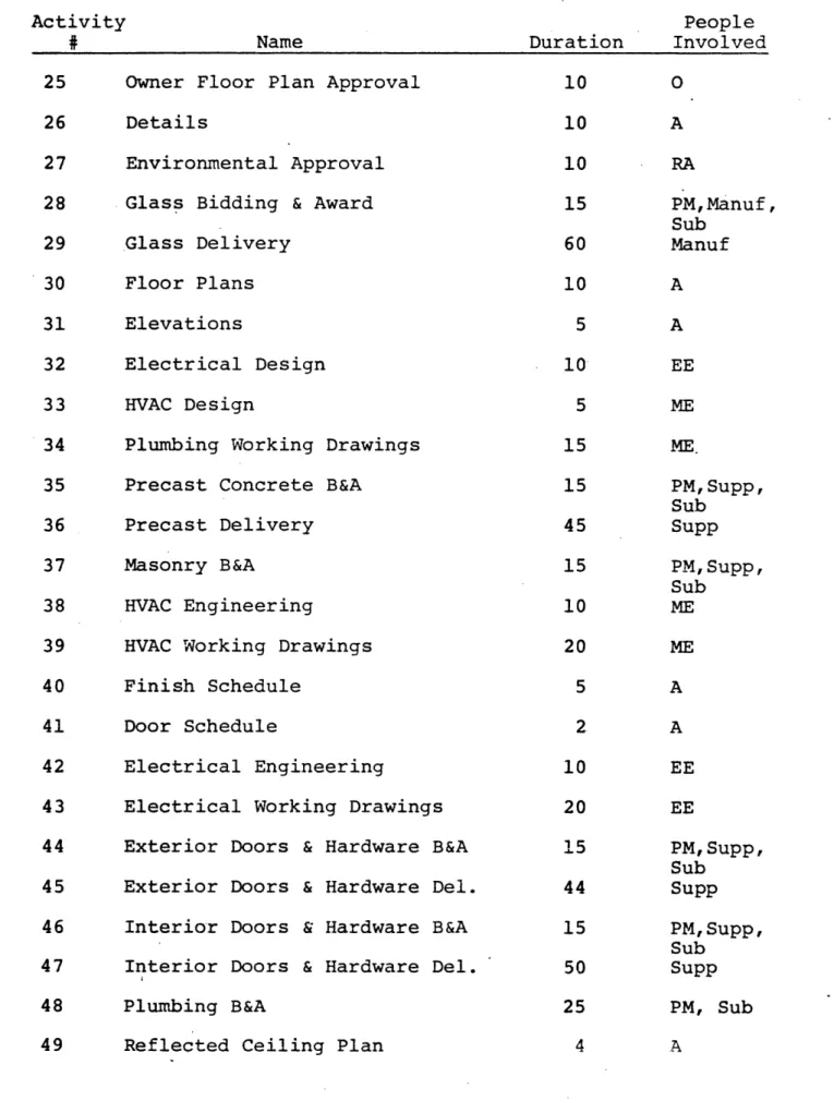
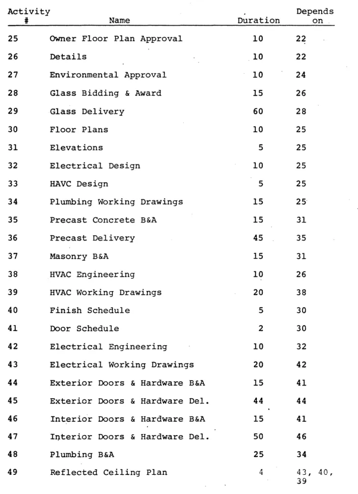
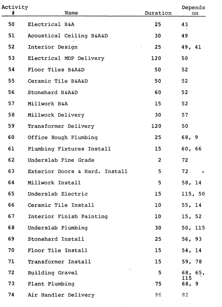
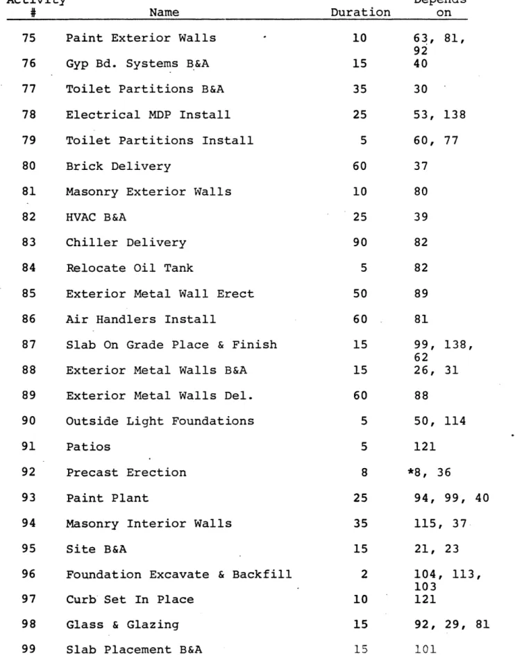
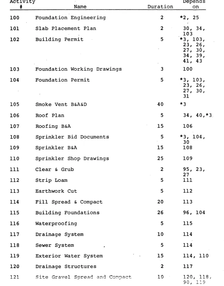
Activity precedence is shown in Tables II and III. The actors involved in each activity are listed in Table I.
From these tables the number of activities for each actor was determined and listed in Table V. The actors depended on by each actor are listed in Tables VI & VII. A graphic
representation of this data is given in Figures 6 and 7.
Chapter III
ACTIVITIES, ACTORS & INTERDEPENDENCIES
In evaluating the coordination problems inherent in the interlacing of design and construction activities in a fast tracked construction project, this study will look at one particular project in great detail. This project will be rearranged hypothetically to depict the design-construction activities of a building being designed and built by conven-tional methods (ie. lump sum bid by a General Contractor after a completed design).
Construction activity precedences will be shown in tabular form. Critical activities and design-construction overlap
will be shown in precedence diagrams. All activity prece-dences and durations are taken directly from Carlson Corpora-tion's CPM network of the actual case study project. The conventional construction case was then hypothetically
extrapolated from this network for the purpose of this study.
DESCRIPTION OF CARLSON CORPORATION
The Carlson Corporation is a design build firm with
offices located in Natick, Massachusetts in addition to offices
in other areas throughout the United States. Carlson
Corpora-tion has a full range of in-house design capabilities and some of the construction trades, including steel erection, masonry, drywall and painting. The company does not typically bid jobs,
-16-but deals with repeat clients and new clients through Carlson's sales office. A project begins in the planning stage with
the Owner and the Carlson design team. A design proposal is then prepared in conjunction with a guaranteed maximum price. If this is acceptable to the Owner a contract is awarded to Carlson Corporation.
The contractual relationship between the parties is shown in figure 1.1
DESCRIPTION OF CASE STUDY PROJECT
The building is constructed of structural steel bearing on concrete foundations. The floor is structural concrete with various finishes. Several wall systems are employed: interior, gypsum board on metal studs and masonry walls. Exterior:
precast concrete, masonry and metal wall systems.
The roof is built-up on a metal deck resting on steel joists. Stairways are prefabricated steel.
On-site is a drainage, sewer and water system. Sidewalks are concrete and parking lots are bituminous concrete paving. Curbing is precast and patios are cast-in-place.
The building is fully sprinkled, smoke vented, heated and air-conditioned.
The case study project is a 120,000 square foot manufacturing plant located in Pennsylvania. The project start-up (contract award) was in November, 1979 and the expected completion date is February, 1980.
On this project the Carlson Corporation of Natick, Massachusetts is the Structural, Mechanical, Electrical,
Soils and Foundation Engineer. Carlson Corporation also
handles the Architectural and Interior Decorating services. Due to a wide range in project localities Carlson Corporation normally hires outside surveyors; they have done so in this case.
All of the trades are subcontracted on this project. The
Project Manager (PM) and design team are off-site and Carlson's Superintendent is on-site.
The project analyzed consists of 142 activities in the fast track case and 143 activities in the conventional case. These are to be performed by eight designers and twenty-one
subcontractors in both cases. In reality there are more than
twenty-one subs as the sitework need not be performed by one sub, and various other work items could be further broken
down as was in fact done by Carlson Corporation. These items
have been combined for simplicity as the design-construct
relationships are not affected by this condensation. There
are of course inherent coordination problems which have thereby been artificially eliminated, but these do not differ substan-tially from the fast track to the conventional construction case. Thus consistency is maintained.
Table I lists all of the activities, the actors involved in each activity and the duration of the activity. Tables II and III list the activities which are depended n for each
-18-activity for the fast track and conventional cases respec-tively. Table IV shows floats associated with each activity.
Table V, VI and VII list all of the actors, the number of activities each actor is involved in and the actors whom
they depend on with the frequency of occurance taken into account.
In the fast track case the design begins with the Project Architectural Definition, Owner and Architect working together. A design proposal is prepared and a Guaranteed Maximum Price
is given to the Owner. This is done by a joint effort of
the design team and the Project Manager.
The Civil and Structural Engineers then come into the
picture. The Civil Engineer prepares working drawings
towards the goal of site plan approval by Regulating Agencies. The Structural Engineer designs the structural componants of the building and prepares a set of contract drawings which can be put out to bid by fabricators and erectors.
In the interum the Achitect prepares preliminary floor plans which are subject to approval by the Owner. The prelimi-nary floor plans are turned over to the Environmental Engineer who obtains environmental approval from the associated
Regulating Agencies.
The Architect continues working on the design, preparing finish schedule, details and evaluations while the Mechanical and Electrical Engineer work on the plumbing, HVAC and
electri-cal design.
is completed that package is put out for lump sum bid by
subcontractors. Thus long lead time items such as steel,
glass, masonry, precast, doors, hardware and electrical components can be set into motion before the overall design
is complete. See figure 2.
Construction can begin anytime after the sitework con-tract is awarded and the site plan and environmental approval have been obtained.
In the conventional case a complete set of bid documents is prepared by the Architect and Engineers. A quantity
surveyor will give advice on costs and the project will be put out to bid by a General Contractor (GC).
The General Contractor's Project Manager will put the project out to bid by subcontractors and prepare an estimate of the cost of the project. This process will take as long as the longest bid item in the fast track case and an estimated
five days for bid and award of contract by the GC. It can
of course be argued that it will take longer but it is herein assumed that because of the early stage in the total design
subcontractors in the fast track case may actually take longer
to prepare a bid than in the conventional case. The difference
in time would in any case be negligible when compared to total project length.
A contract is awarded to the GC, the GC in turn awards contracts to the subcontractor, and construction begins. At
this point all plans have been approved by the mrner and any
-20-associated Regulating Agencies, and all building permits have
been obtained. See figure 3.
Construction activity precedence and duration is the same in both cases, the difference lying in the interlacing of the design process in the fast track case. Critical paths for both cases are shown in figure 4 and figure 5.
L is 1 =1 A c -, &t I If ., *X -. -.~ iS t
!
I
1-> i z Z:4-IN- '2n - t, - L-(- LF A:fll --- - --I -, SE--l -a. . .", 41 1 ,' t7t-, ...1-1 7i,- -22-tAS 131-Q
,r) Ia
5
(D-4
JN wT-IQi"L-
-UTIM
,KTPX
n $-Iq %I
-'t
1%~ -JiL
SZ.
EI
) Be~~r .
t~
I
a*l
1I
~IEAT TL,
kITlAl
FA
r-k7IL
-
4rOJ.
XtjL Pt.
m
bTT
i
k 4.
a
TLI.
VIVb5.
I
TLT.
GC,Z:L +
-
7
1T2
W
C
T
T
i
I
IIVr
Mk EVb tT
o.
K
(TD
a
I
51xD CkV
V.
Ws A
K:
'S W
\VLL
5 8LIt'
w
'
,
I.L
tLtt.
A,I
CLr
C
,LE'
1
CW'/'lWI 69rrLt
Ct
I
bqtf2Tx~TI-
4PMrLCTIPrt
..,',,,,,,,
Vq kTIc'-T ZU?5IJA L
L
15 Wu5G[rnmTIOMrlIL
CITVIAL Fi
rI1Aq
-
5
OVE-AIT!VA
Mbbr --
itA,EY/rf
Jr
ALT Vt h
/l-.
VRELIt1.
r-L
JklPN [5t-ApL
ItVAU P\tYrI-N-ttv AD
I
tr$
A
kV
THr
r
vuvrb
-tT
E¶9 ML\V/m
-~
~ ~ ~ ~1
4
JqIR[ LF9
jC5
D PAS 1 0 p Sj
I
prt
P
tk4
I
q&LL
rA~~rI~~
DfZ.
4?
I
LK.
t
m
.
Z5,o
T.
T
,5,~
~,7T
,o~a
,¥D5.
CLLI6,---
--lSL~_
~-1~lb!'
5 PafliCt
S ?M.,
fl.
ffCl't0
\tT:
4rrl~tC
~PMTLi
Cotr" r
rTAbL I
Duration in days
List shows actors involved in each activity
- Owner
A - Architect
SE - Structural Engineer ME - Mechanical Engineer EE - Electrical Engineer ENE - Environmental Engineer
CE - Civil Engineer FE - Foundation Engineer ID - Interior Designer RA - Regulating Agencies PM - Project Manager Sub - Subcontractor Supp - Supplier
-26-PO
L
I VOLVD
I ACTIVITIS
AiI I I -_TABL I
Name
Project Architectural Definition Structural Engineering
Structural Working Drawings Structural Bidding and Award Structural Shop Drawings Steel Delivery
Joist Delivery
Steel & Joists Erect Roof Deck Erect
Office Rough Electrical Interior Studs Erect Interior Gypsum Board
Interior Doors & Hardware Install Paint Interior Walls
Acoustical Ceiling Office Finish HVAC Office Electrical Complete Electrical Substantial Completion HVAC Completion
Civil Working Drawings Preliminary Floor Plans Site Plan Approval
Environmental Engineering Duration 5 3 5 10 10 100 100 25 10 25 15 10 15 15 20 10 5 5 5 5 5 5 5 5 People Involved O,A SE SE Fab,Erec, PM SE, Fab Fab Fab Erec Erec Sub Sub Sub Sub Sub Sub Sub Sub Sub Sub CE A CE, ENE RA Activit] #o. 1 2 3 4 5 6 7 8 9 10 11 12 13 14 15 16 17 18 19 20 21 22 23 24
TABLE I Contd. Activity 25 26 27 28 29 30 31 32 33 34 35 36 37 38 39 40 41 42 43 44 45 46 47 48 49 Name
Owner Floor Plan Approval Details
Environmental Approval Glass Bidding & Award Glass Delivery
Floor Plans Elevations
Electrical Design HVAC Design
Plumbing Working Drawings Precast Concrete B&A
Precast Delivery Masonry B&A
HVAC Engineering
HVAC Working Drawings Finish Schedule
Door Schedule
Electrical Engineering
Electrical Working Drawings Exterior Doors & Hardware B&A Exterior Doors & Hardware Del.
Interior Doors & Hardware B&A Interior Doors & Hardware Del. Plumbing B&A
Reflected Ceiling Plan
Duration 10 10 10 15 60 10 5 10 5 15 15 45 15 10 20 5 2 10 20 15 44 15 50 25 4 People Involved 0 A RA PM,Manuf, Sub Manuf A A EE ME ME PM, Supp, Sub Supp PM, Supp, Sub ME ME A A EE EE PM, Supp, Sub Supp PM, Supp, Sub Supp PM, Sub A
-28-__
TABLE I Contd.
Activity
#
NameElectrical B&A
Acoustical Ceiling B&A&D Interior Design
Electrical MDP Delivery Floor Tiles B&A&D
Ceramic Tile B&A&D Stonehard B&A&D Millwork B&A
Millwork Delivery Transformer Delivery Office Rough Plumbing Plumbing Fixtures Install Underslab Fine Grade
Exterior Doors & Hard. Install Millwork Install
Underslab Electric Ceramic Tile Install
Interior Finish Painting Underslab Plumbing
Stonehard Install Floor Tile Install Transformer Install Building Gravel Plant Plumbing
Air Handler Delivery
Duration 25 30 25 120 50 50 60 15 30 120 25 15 2 5 5 15 10 10 30 25 15 15 5 75 86 People Involved PM, Supp, Sub PM, Supp, Sub ID Supp PM, Supp, Sub PM, Supp, Sub PM,Manuf, Sub PM,Supp, Sub Supp Supp Sub Sub Sub Sub Sub Sub Sub Sub Sub Sub Sub Sub Sub Sub Manu f 50 51 52 53 54 55 56 57 58 59 60 61 62 63 64 65 66 67 68 69 70 71 72 73 74
TABLE I Contd. Activity 75 76 77 78 79 80 81 82 83 84 85 86 87 88 89 90 91 92 93 94 95 96 97 98 99 f Name Paint Exterior Walls Gyp Bd. Systems B&A Toilet Partitions B&A Electrical MDP Install Toilet Partitions Install Brick Delivery
Masonry Exterior Walls HVAC B&A
Chiller Delivery Relocate Oil Tank
Exterior Metal Wall Erect Air Handlers Install
Slab On Grade Place & Finish Exterior Metal Walls B&A Exterior Metal Walls Del. Outside Light Fundations
Patios
Precast Erection Paint Plant
Masonry Interior Walls Site B&A
Foundation Excavate & Backfill Curb Set In Place
Glass & Glazing Slab Placement B&A
Duration 10 15 35 25 5 60 10 25 90 5 50 60 15 15 60 5 5 8 25 35 15 2 10 15 15 People Involved Sub PM,Manuf, Sub PM,Manuf, Sub Sub Sub Supp Sub PM, Sub Manuf Sub Sub Sub Sub PM,Sub Manuf Sub Sub Sub Sub Sub PM, Sub Sub Sub Sub"., PM, Sub 30
-TABLE I Contd.
Name
Foundation Engineering Slab Placement Plan Building Permit
Foundation Working Drawings Foundation Permit
Smoke Vent B&A&D Roof Plan
Roofing B&A
Sprinkler Bid Documents Sprinkler B&A
Sprinkler Shop Drawings Clear & Grub
Strip Loam Earthwork Cut
Fill Spread & Compact Building Foundations Waterproofing
Drainage System Sewer System
Exterior Water System Drainage Structures
Site Gravel Spread And Compact Sidewalks
Railroad Track Site Fine Grade
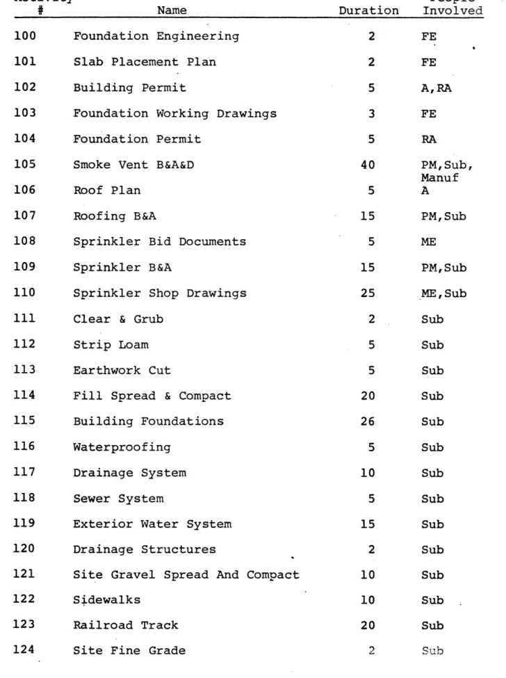
Duration 2 2 5 3 5 40 5 15 5 15 25 2 5 5 20 26 5 10 5 15 2 10 10 20 2 People Involved FE FE A,RA FE RA PM, Sub, Manuf A PM, Sub ME PM, Sub ME,Sub Sub Sub Sub Sub Sub Sub Sub Sub Sub Sub Sub Sub Sub Sub Activit3
#
100 101 102 103 104 105 106 107 108 109 110 111 112 113 114 115 116 117 118 119 120 121 122 123 124TABLE I Contd. Activity
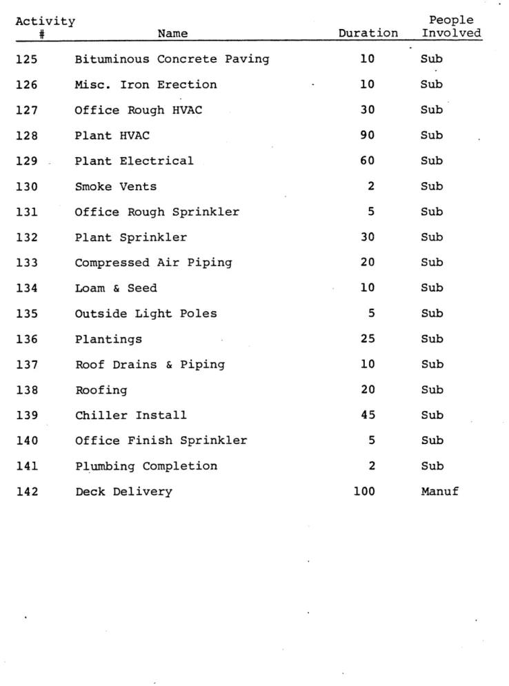
#
125 126 127 128 129 130 131 132 133 134 135 136 137 138 139 140 141 142 . NameBituminous Concrete Paving Misc. Iron Erection
Office Rough HVAC Plant HVAC
Plant Electrical Smoke Vents
Office Rough Sprinkler Plant Sprinkler
Compressed Air Piping Loam & Seed
Outside Light Poles Plantings
Roof Drains & Piping Roofing
Chiller Install
Office Finish Sprinkler Plumbing Completion Deck Delivery Duration 10 10 30 90 60 2 5 30 20 10 5 25 10 20 45 5 2 100 People Involved Sub Sub Sub Sub Sub Sub Sub Sub Sub Sub Sub Sub Sub Sub Sub Sub Sub Manuf 32
-TAbLS
]E
H
Duration in days
*critical activity
Activity on left depends on activity on right. Activity on right given by activity number.
ME
ITRK<
AT!VIT
'
F,
RCC
TADLL
TT
Activity 1 2 3 4 5 6 7 8 9 10 11 12 13 14 15 16 17 18 19 20 21 22 23 24 NameProject Architectural Definition Structural Engineering
Structural Working Drawings Structural Bidding and Award Structural Shop Drawings Steel Delivery
Joist Delivery
Steel & Joists Erect Roof Deck Erect
Office Rough Electrical Interior Studs Erect Interior Gypsum Board
Interior Doors & Hardware Install Paint Interior Walls
Acoustical Ceiling Office Finish HVAC Office Electrical Complete Electrical Substantial Completion HVAC Completion
Civil Working Drawings Preliminary Floor Plans Site Plan Approval
Environmental Engineering Duration 5 3 5 15 10 100 100 25 10 25 15 10 15 15 20 10 5 5 5 5 5 5 5 5 Depends on 0 *1 *2 *3 *4 *5 *6 *7 *8 129 *10 *11 *12 *13 *14 127 *15, *10 *17, 129 *18 *19 *1 *1 21 22 -34-'
TABLE II Contd.
Activity
#
NameOwner Floor Plan Approval Details
Environmental Approval Glass Bidding & Award Glass Delivery
Floor Plans Elevations
Electrical Design HAVC Design
Plumbing Working Drawings Precast Concrete B&A
Precast Delivery Masonry B&A
HVAC Engineering
HVAC Working Drawings Finish Schedule
Door Schedule
Electrical Engineering
Electrical Working Drawings Exterior Doors & Hardware B&A Exterior Doors & Hardware Del.
Interior Doors & Hardware B&A Interior Doors & Hardware Del. Plumbing B&A
Reflected Ceiling Plan
Duration 10 10 10 15 60 10 5 10 15 15 15 45 15 10 20 5 2 10 20 15 44 15 50 25 4 25 26 27 28 29 30 31 32 33 34 35 36 37 38 39 40 41 42 43 44 45 46 47 48 49 Depends on 22 22 24 26 28 25 25 25 25 25 31 35 31 26 38 30 30 32 42 41 44 41 46 34 43, 40, 39
TABLE II Contd. Activity 50 51 52 53 54 55 56 57 58 59 60 61 62 63 64 65 66 67 68 69 70 71 72 73 74 ? Name Electrical B&A
Acoustical Ceiling B&A&D Interior Design
Electrical MDP Delivery Floor Tiles B&A&D
Ceramic Tile B&A&D Stonehard B&A&D Millwork B&A
Millwork Delivery Transformer Delivery Office Rough Plumbing Plumbing Fixtures Install Underslab Fine Grade
Exterior Doors & Hard. Install Millwork Install
Underslab Electric Ceramic Tile Install Interior Finish Painting Underslab Plumbing
Stonehard Install Floor Tile Install Transformer Install Building Gravel Plant Plumbing
Air Handler Delivery
Duration 25 30 25 120 50 50 60 15 30 120 25 15 2 5 5 15 10 10 30 25 15 15 5 75 86 -36-Depends on 43 49 49, 50 52 52 52 52 57 50 68, 60, 72 72 58, 115 55, 15, 50, 56, 54, 59, 68, 115 68, 82 41 9 66 14 50 14 52 115 93 14 78 65, 9
TABLE II Contd. Activity
#
75 76 77 78 79 80 81 82 83 84 85 86 87 88 89 90 91 92 93 94 95 96 97 98 99 NamePaint Exterior Walls Gyp Bd. Systems B&A Toilet Partitions B&A Electrical MDP Install Toilet Partitions Install Brick Delivery
Masonry Exterior Walls HVAC B&A
Chiller Delivery Relocate Oil Tank
Exterior Metal Wall Erect Air Handlers Install
Slab On Grade Place & Finish Exterior Metal Walls B&A Exterior Metal Walls Del. Outside Light Foundations Patios
Precast Erection Paint Plant
Masonry Interior Walls Site B&A
Foundation Excavate & Backfill Curb Set In Place
Glass & Glazing Slab Placement B&A
Duration 10 15 35 25 5 60 10 25 90 5 50 60 15 15 60 5 5 8 25 35 15 2 10 15 15 Depends on 63, 81, 92 40 30 53, 138 60, 77 37 80 39 82 82 89 81 99, 138, 62 26, 31 88 50, 114 121 *8, 36 94, 99, 40 115, 37 21, 23 104, 113, 103 121 92, 29, 81 101 -T
TABLE II Contd.
Activity
# Name
Foundation Engineering Slab Placement Plan Building Permit
Duration 2
2 5
Foundation Working Drawings Foundation Permit
3 5
Smoke Vent B&A&D Roof Plan
Roofing B&A
Sprinkler Bid Documents Sprinkler B&A
Sprinkler Shop Drawings Clear & Grub
Strip Loam Earthwork Cut
Fill Spread & Compact Building Foundations Waterproofing
Drainage System Sewer System
Exterior Water System Drainage Structures
Site Gravel Sread and Comnact
40 5 15 5 15 25 2 5 5 20 5 26 10 5 15 2 10 Depends on *2, 25 30, 34, 103 *3, 103, 23, 26, 27, 30, 34, 39, 41, 43 100 *3, 103, 23, 26, 27, 30, 31 *3 34, 40,*3. 106 *3, 104, 30 108 109 95, 23, 27 111 112 113 96, 104 115 114 114 114, 110 117 120, 118 90, 1 -38-100 101 102 103 104 105 106 107 108 109 110 111 112 113 114 115 116 117 118 119 120 121
-TABLE II Contd.
Activity
#
NameSidewalks
Railroad Track Site Fine Grade
Bituminous Concrete Paving Misc. Iron Erection
Office Rough HVAC Plant HVAC
Plant Electrical Smoke Vents
Office Rough Sprinkler Plant Sprinkler
Compressed Air Piping Loam & Seed
Outside Light Poles Plantings
Roof Drains & Piping Roofing
Chiller Install
Office Finish Sprinkler Plumbing Completion Duration 10 20 2 10 10 30 90 60 2 5 30 20 10 5 25 10 20 45 5 2 Deck Delivery 100 Depends on 121 121 122, 91 116, 97 I 84 123, 124 *8 *9 *9 *9 *9, 105 105, *9 *9, 110 *9 125 125 125 *9, 68, 120 126,*9, 107, 130 137, 92, 85, 81 138, 83 131, 15 18, 133, 73, 61 *5 122 123 124 125 126 127 128 129 130 131 132 133 134 135 136 137 138 139 140 141 142
-MVEMTI RMAL ACTIVITY
FLE NLFS
TABLL
I
Activit) 0 1 2 3 4 5 6 7 8 9 10 11 12 13 14 15 16 17 18 19 20 21 22 T Name Project Start-upProject Architectural Definition Structural Engineering
Structural Working Drawings Structural Bid and Award Structural Shop Drawings Steel Delivery
Joist Delivery
Steel & Joists Erect Roof Deck Erect
Office Rough Electrical Interior Studs Erect Interior Gypsum Board
Interior Doors & Hardware Install Paint Interior Walls
Acoustical Ceiling Office Finish HVAC Office Electrical
Complete Electrical Substantial Completion HVAC Completion
Civil Working Drawings Preliminary Floor Plans
Duration 1 5 3 5 15 10 100 100 25 10 25 15 10 15 15 20 10 5 5 5 5 5 Depends on *1 2 143 *4 *5 *5 *7 *8 129 *10 *11 *12 *13 *14 127 *15,*10 *17, 129 *18 *19 *1 *1
-40-TABLE III Contd. Activity 23 24 25 26 27 28 29 30 31 32 33 34 35 36 37 38 39 40 41 42 43 44 45 46 47 Name Site Plan Approval
Environmental Engineering Owner Floor Plan Approval Details
Environmental Approval Glass Bid & Award
Glass Delivery Floor Plans Elevations
Electrical Design HVAC Design
Plumbing Working Drawings Precast Concrete B&A
Precast Delivery Masonry B&A
HVAC Engineering
HVAC Working Drawings Finish Schedule
Door Schedule
Electrical Engineering
Electrical Working Drawings Exterior Doors & Hardware B&A Exterior Doors & Hardware Del.
Interior Doors ¢ Hardware B&A
Interior Doors & Hardware Del.
Duration 5 5 10 10 10 15 60 10 5 10 5 15 15 45 15 10 20 5 2 10 20 15 44 15 50 Depends on 21 *22 *22 *22 24 143 28 *25 *25 *25 *25 *25 143 35 145 *33 *38 30 30 32 42 143 44 143 *14
TABLE III Contd. Activity # 48 49 50 51 52 53 54 55 56 57 58 59 60 61 62 63 64 65 66 67 68 69 70 71 72 T Name Plumbing B&A
Reflected Ceiling Plan Electrical B&A
Acoustical Ceiling B&A&D Interior Design
Electrical MDP Delivery Floor Tiles B&A&D
Ceramic Tile B&A&D Stonehard B&A&D Millwork B&A
Millwork Delivery Transformer Delivery Office Rough Plumbing
Plumbing Fixtures Install Underslab Fine Grade
Exterior Doors & Hard. Install Millwork Install
Underslab Electric Ceramic Tile Install Interior Finish Painting Underslab Plumbing
Stonehard Install Floor Tile Install Transformer Install Buidirg Gravel Duration 25 4 25 30 25 120 50 50 60 15 30 120 25 15 2 5 5 15 10 10 30 25 15 15 5S Depends on 143 40, 39, 43 143 143 41 *50 143 143 143 143 57 *50 68,*9 60, 66 72 72 58, 14 115, *50 55, 14 15, 52 *50, 115 56, 93 14, 54 59, 78 65, 63, 115
-h2-TABLE III Dontd. Activity # 73 74 75 Name Plant Plumbing
Air Handler Delivery Paint Exterior Walls
Duration 75 86 10 Depends on *9 68 82 63, 81, 92
76 Gyp Bd. Systems B&A
77 Toilet Partitions B&A
78 Electrical MDP Install
79 Toilet Partitions Install
80 Brick Delivery
81 Masonry Exterior Walls
82 HVAC B&A
83 Chiller Delivery
84 Relocate Oil Tank
85 Exterior Metal Wall Erect
86 Air Handlers Install
87 Slab On Grade Place & Finish
88 Exterior Metal Walls B&A
89 Exterior Metal Walls Del.
90 Outside Light Foundations
91 Patios 92 Precast Erection 93 Paint Plant 15 35 25 5 60 10 25 90 5 50 60 15 15 60 5 5 8 25
94 Masonry Interior Walls
95 Site B&A
96 Foundation Excavate & Backfill
35 15 2 143 143 53, 138 60, 77 37 80 143 82 82 89 81 99, 62, 138 143 88 *50, 114 121 *8, 36 40, 94, 99 115, 37 143 I0?, 14, f
TABLE III Contd. Activity
#
97 98 99 100 101 102 Name DurationCurb Set In Place Glass & Glazing Slab Placement B&A Foundation Engineering Slab Placement Plan
Building Permit Depends on 10 121 15 29, 81, 92 15 143 2 *25 2 30, 34, 103 5 26,*39, 43, 34, 30,*3, 103, 23, 41
Foundation Working Drawings Foundation Permit
3
5
Smoke Vent B&A&D Roof Plan
40
5
RoQofing B&A
Sprinkler Bid Documents Sprinkler B&A
Sprinkler Shop Drawings Clear & Grub
15 5 15 25 2 Strip Loam Earthwork Cut
Fill Spread & Compact Building Foundations Waterproofing Dr ainae Sy temn 5 5 20 26 10 1 0 100 26, 30, 31, *3, 103, 27, 23 143 34,*39, *3 143 *3, 30 143 109 23, 27, 95 111 112 113 96 115 114 -44-103 104 105 106 107 108 109 110 111 112 113 114 115 116 117 r
TABLE III Contd. Activity
#
118 119 120 121 122 123 124 125 126 127 128 129 130 131 132 133 134 135 136 137 138 Name Duration Sewer SystemExterior Water System Drainage Structures
Site Gravel Spread and Compact
Sidewalks
Railroad Track Site Fine Grade
Bituminous Concrete Paving Misc. Iron Erection
Office Rough HVAC Plant HVAC
Plant Electrical Smoke Vents
Office Rough Sprinkler Plant Sprinkler
Compressed Air Piping Loam & Seed
Outside Light Poles Plantings
Roof Drains & Piping
Roofing Chiller Install Depends on 5 114 15 110, 114 2 117 10 90, 118, 119, 120 10 121 20 121 2 84, 91, 97, 116, 122 10 123, 124 10 *8 30 *9 90 *9 60 *9 2 *9, 105 5 *9, 105 30 *9, 110 20 *9 10 125 5 125 25 125 10 *9, 68, 120 20 *9, 81, 85, 92, 107, 126, 130, 137 T eMS 139
TABLE III Contd.
Activity
#
Name Duration
Office Finish Sprinkler Plumbing Completion
5 *15, 131
2
100 Deck Delivery
B&A By General Contractor 5
Contract Documents Complete 0
*18, 61, 73, 133 *5 144 49, 52, 101, 102, 104, 106, *108, *82 140 141 142 143 144 Depends on Duration Name
TAbLL
IT
Duration in days
Activity float given in days for both fast track and conventional case.
ACTIViTY
DUKAT71Mt
fLOAT
Activity
# Name Duration
Project Architectural Definition Structural Engineering
Structural Working Drawings Structural Bid and Awards Structural Shop Drawings Steel Delivery
Joist Delivery
Steel & Joists Erect Roof Deck Erect
Office Rough Electrical Interior Studs Erect Interior Gypsum Board
Interior Doors & Hardware Install Paint Interior Walls
Acoustical Ceiling Office Finish HVAC Office Electrical Complete Electrical
Substantial Completion HVAC Completion
Civil Working Drawings Preliminary Floor Plans
Site Plan Approval
5 3 5 15 10 100 100 25 10 25 15 10 15 15 20 10 5 5 5 5 5 5 5 - Fast Track 0 0 0 0 0 0 0 0 0 0 0 0 0 0 0 0 0 0 0 0 69 38 84
-48-TAbLL
Z
FLOAT 2 3 1 112 3 4 5 6 7 8 9 20 21 22 23 14 15 16 17 18 19 20 21 22 23 Conven-tional 0 42 0 10 0 0 0 0 0 0 0 0 0 0 0 0 0 0 0 0 38 0 3 8 uL
i ITABLE IV Contd.
Activity
Name
Environmental Engineering Owner Floor Plan Approval Details
Environmental Approval Glass Bidding & Award Glass Delivery
Floor Plans Elevations
Electrical Design HVAC Design
Plumbing Working Drawings Precast Concrete B&A
Precast Delivery Masonry B&A
HVAC Engineering
HVAC Working Drawings Finish Schedule
Door Schedule
Electrical Engineering
Electrical Working Drawings Exterior Doors & Hardware B&A Exterior Doors & Hardware Del.
Interior Doors & Hardware B&A Interior Doors & Hardware Del. Plumbing B&A niv 4- -10 10 10 10 15 60 10 5 10 5 15 15 45 15 10 20 5 2 10 20 15 44 15 50 25 FLOAT Fast Track 24 25 26 27 28 29 30 31 32 33 34 35 36 37 38 39 40 41 42 43 44 45 46 47 48 Conven-tional 28 0 38 28 10 138 2 32 0 20 10 10 10 0 0 21 2 5 5 10 211 i 0 161 0 69 36 43 74 138 138 79 38 68 78 98 105 105 38 78 78 74 101 68 68 211 211 161 161 98 ! uA A L .c%.X.v%. l
TABLE IV Contd.
FLOAT
Activity Fast
Conven-Name Duration Track
Name Duration Track
49 Reflected Ceiling Plan 4
50 Electrical B&A 25
51 Acoustical Ceiling B&A&D 30
52 Interior Design 25
53 Electrical MDP Delivery 120
54 Floor Tiles B&A&D 50
55 Ceramic Tile B&A&D 50
56 Stonehard B&A&D 60
57 Millwork B&A 15
58 Millwork Delivery 30
59 Transformer Delivery 120
60 Office Rough Plumbing 25
61 Plumbing Fixtures Install 15
62 Underslab Fine Grade 2
63 Exterior Doors & Hard. Install 5
64 Millwork Install 5
65 Underslab Electric 15
66 Ceramic Tile Install 10
67 Interior Finish Painting 10
68 Underslab Plumbing 30
69 Stonehard Install 25
70 Floor Tile Install 15
71 Transformer Install 15 72 Building Gravel 5 149 68 194 149 68 169 167 149 184 184 93 35 8 57 148 30 34 346 5 34 70 20 68 57 tional 1 0 194 3 68 169 167 149 10 184 93 35 8 57 148 30 34 6 5 34 70 20 68 57 73 Plant Plumbing 75 73 73
-50-TABLE IV Contd.
FLOAT
Activity Fast
Conven-#* _Name Duration- Track tional
74 Air Handler Delivery 86 88
75 Paint Exterior Walls 10 142
76 Gyp Bd. Systems B&A 15 183
77 Toilet Partitions B&A 35 253
78 Electrical MDP Install 25 68
79 Toilet Partitions Install 5 20
80 Brick Delivery 60 38
81 Masonry Exterior Walls 10 38
82 HVAC B&A 25 88
83 Chiller Delivery 90 103
84 Relocate Oil Tank 5 201
85 Exterior Metal Wall Erect 50 38
86 Air Handlers Install 60 55
87 Slab On Grade Place & Finish 15 15
88 Exterior Metal Walls B&A 15 48
89 Exterior Metal Walls Del. 60 48
90 Outside Light Foundations 5 136
91 Patios 5 139
92 Precast Erection 8 27
93 Paint Plant 25 70
94 Masonry Interior Walls 35 89
95 Site B&A 15 69
96 Foundation Excavate & Backfill 2 14
97 Curb Set In Place 10 134
88 142 10 253 68 20 38 38 0 103 201 38 55 15 48 48 136 139 27 70 89 10 14 134 93 Glass Gz - 4nc 13 62 62
I
I
TABLE IV Contd.
Activity Fast
Name Duration
99 Slab Placement B&A 15
100 Foundation Engineering 2
101 Slab Placement Plan 2
102 Building Permit 5
103 Foundation Working Drawings 3
104 Foundation Permit 5
105 Smoke Vent B&A&D 40
106 Roof Plan 5
107 Roofing B&A 15
108 Sprinkler Bid Documents 5
109 Sprinkler B&A 15
110 Sprinkler Shop Drawings 25
111 Clear & Grub 2
112 Strip Loam 5
113 Earthwork Cut 5
114 Fill Spread & Compact 20
115 Building Foundations 26
116 Waterproofing 5
117 Drainage System 10
118 Sewer System 5
119 Exterior Water System 15
120 Drainage Structures 2
121 Site Gravel Spread and Compact 10
122 Sidewalks 10 FLOAT Track 166 84 168 73 84 79 148 118 168 168 168 168 14 14 14 59 14 157 59 136 126 59 126 134 Conven-tional 10 30 23 20 30 28 148 20 25 0 10 168 14 14 14 59 14 157 59 136 126 59 126 134 123 Railr-oad Track 20 125 12
i
[
-52-TABLE IV Contd.
FLOAT
Activity Fast
Conven-$ Name Duration Track tional
124 Site Fine Grade 2
125 Bituminous Concrete Paving 10
126 Misc. Iron Erection 10
127 Office Rough HVAC 30
128 Plant HVAC 90
129 Plant Electrical 60
130 Smoke Vents 2
131 Office Rough Sprinkler 5
132 Plant Sprinkler 30
133 Compressed Air Piping 20
134 Loam & Seed 10
135 Outside Light Poles 5
136 Plantings 25
137 Roof Drains & Piping 10
138 Roofing 20
139 Chiller Install 45
140 Office Finish Sprinkler 5
141 Plumbing Completion 2 142 Deck Delivery 100 134 125 25 90 55 80 23 140 120 128 141 146 126 15 15 70 10 3 25 134 125 25 90 55 80 23 140 120 128 141 146 126 15 15 70 10 3 25 __
TAbLL:
CIZ
.TAL
KEY
:
Table lists the number of activitieseach actor is involved in and how many of these activities are critical for both the fast track and conventional case.
-54-NUMBLR
O_
ACTIVITIL Ft
PrLDRfT
TAFL
b5Y
ACTOr
FAST TRACK
#of
Subcontractors Activities Critical
Mechanical 9 1 Electrical 8 3 Plumbing 7 0 Erection 6 2 Sprinkler 4 0 Precast Erector 2 0 Glazing 2 0 Millwork 2 0 Flooring 4 0
Doors & Hardware 4 1
Masonry 3 0
Drywall & Partitions 3 0
Formwork 2 0 Finish Concrete 4 0 Waterproofing 1 0 Roofing 2 0 Sitework 20 0 Toilet Partitions 2 0 Ceiling 2 1 Painting 4 0 Railroad 1 0 CONVENTIONAL #'of # Activities Critical 9 1 8 4 7 1 6 2 4 0 2 0 2 0 2 0 4 0 4 1 3 . 0 3 0 .2 0 4 0 1 0 2 0 20 0 2 0 2 1 4 0 1 0 Designers Architect 12 1 i 12 3
TAbLL
V
((Oi'TD.)
FAST TRACK # of # Activities Critical Structural Engineer 3 3 Mechanical Engineer 6 0 Electrical Engineer 3 0 Civil Engineer 2 0 Foundation Engineer 4 0 Environmental Engineer 1 0 Interior Designer 1 0 Project Manager 22 1 Owner 3 1 Regulating Agencies 4 0 Suppliers CONVENTIONAL # of # Activities Critical 3 1 6 3 3 0 2 0 4 0 1 0 1 0 22 4 3 2 4 0 Fabricator, Steel 4 4 Mechanical Manufacturer 4 0 Electrical 3 0 Mansonry 2 0 Precast Concrete 2 0 Glazing 2 0 Millwork 2 0 Flooring 3 0 Toilet Partitions 1 0 Ceiling 1 0Doors & Hardware 4 0
Miscellaneous Iron 1 0 Metal Walls 2 0 4 4 4 1 3 1 2 0 2 0 2 0 2 0 3 0 1 0 1 0 4 0 1 0 2 0
-56-TAbLL:T
-L77
II
Tables list the actors which each actor depends
on. Derived from tables I, II, & III. Frequency
of dependency is to the left of the actor.
F\?1
TACr: ACIT6R2
PLPfI{PP OH
ctror
Subcontractors Manaqement
-Depend& on
Desiqners Subcontractors -Suppliers
Mechanical 1)PM !1)ME )SE 1)*Ceil 2)Mech
1)Spri
2) Roof 2)Erect
Electrical l)PM 1)EE 1 )Formwork 2)Elect
1) Roof
)Erect
Plumbing 1)PM 1)ME 4 4)Erector
1)Floor 1)Formwork
Erection 1)*PM 1)A 1)*SE 1)Formwork 'l)Metal
1)Mason Wall
:2)*Fabri-J cator
Sprinkler 1) PM 1)ME 2)Erector
1)Ceiling sub
Precast Erector 1) PM 1)A 1) Erector 1) Precast
Glazing 1)PM 1)A 1) Mason 1) Glazing
1) Precast
Millwork l)PM 1)FD 1)Paint
1)Mill-work
Flooring 3)PM 3)ID 3)Paint
3)Floor-ing Doors & Hardware 2)PM 1)A 1)Erector 2)Door &
1)Gyp Hard
1) Mason
Masonry 1)PM 1)A 1)Formwork 2)Masonry
Drywall & Partitions 1)PM 1)A ! )Glazing 1)Drywall 1)Roof 1) Finish Conc 1)*Elec 1)Mech 1)Plumb -5B--- ·-5B--- · . ---^---·---I---·--- - --- j --- ' ---- --- --
- D
I
z-TABLE V Contd.
,Management -Designers Subcontrators Suppliers
rX_ - I
_ ~~~~Management -Designers -ucnrcosSuppliers
Formwork . 1)RM 1)PM 2) Site 1) Elec Finish Concrete Waterproofing 1)PM 1)FE 1)PM 3) Site l)Finish Conc 1)Formwork Roofing 1) PM Sitework 4)RA 1)PM 1)A 1)FE 2)Surveyor 2)CE 1)ENE l)Mason 1) Mechanical 3)*Erector 1)Plumb 1) Precast 1) Waterproof l)Fin Conc 1) Rail l)Mech l)Elec 2)Formwork 1) Spri
Toilet Partitions 1) PM 1)A 1)Floor 1) Partit
Ceiling Painting 1)PM 1)PM 1)A 1)A 1)FD 1) *Paint 1) Precast 1) Roof 2)*Door 1)Dwl 1)Ceil 2)Mason Railroad
Designers Management Designers Suppliers
Architect 3)0 Structural Engineer 1)CE 1) Surveyor 2)EE 5)ME 2)SE 1)FE 1) *A 1)*Fabricator 1)Ceil 1)PM 1) Site ·--- -- ·--- ·--- -I---·· -I- ---- --
--TABLE VI Contd.
Management- Designers -Suppliers
Mechanical Engineer Electrical Engineer Civil Engineer Foundation Engineer 2)0- 1) SE .- .l1 ~ _ - J)A 1) 0 1)A 2)A 1)ME 1)SE
Environmental Engineer 1)A
Interior Designer 2)A
Project Manager 1)CE
1)FE 1)RA 1) Surveyor 2)*SE 9)A 4)ME 1)EE 4)ID Owner 1)A Surveyor 1)CE
Regulating Agencies 1)ME
1)EE 2)SE 1)CE 1)ENE 2)FE 4)K Suppliers Fabricator, Steel 1)*PM Mechanical Manufacturer 1)PM Electrical l)PM - 0--1) Spri 1) *SE 1) ME 1) EE ... -.. ._ .. . .. .
TABLE VI Contd.
Management Designers
Masonry 1)PM 1)A
Precast Concrete 1)PM 1)A
Glazing 1)PM 1)A
Millwork l) PM 1)ID
Flooring 3)PM 3)ID
Toilet Partitions 1)PM 1)A
Ceiling 1)PM 1)A
Doors & Hardware 2)PM 2)A
Miscellaneous Iron 1)PM
COQMVfMTlzFTIAL:
ACTL,
'PDP
OiDt
Subcontractors MechanicalTAbLL
I
PezetpbS ° Maniaement - qubcontractors 1)PM 1) *Ceil 1) Spri 2) Roof 2) Erect -Suppliers 2)Mech Electrical 1)PM 1)Formwork 1)Roof 1)Erect 2)Electri-cal Plumbing 1)PM 4) Erect : 1) Floor 1) Formwork Erection 1)PM 1)Formwork 1) Mason l)Metal wall 2)**Fabri-cator Sprinkler Precast Erector 1)PM 1)PM 2) Erect 1) Ceiling 1)Erect 1) Precast 1)Mason l)Precast Erect 1)GlazingMillwork 1)PM 1) Paint 1)Millwork
Flooring
Doors & Hardware
Masonry
Drywall & Partitions
~~~~~~~~~~~~~~~~~~~~~Formwork {~~ ... j.~~~~~~~~~~~~~~~~~~~~~~~~~~~~~~~~~~~~~~~~~ Fo rmwo r k~~~~~~~~~~~~~~~~~~~~~~~~~~~~~~~~~~~~~~~~~~~~~~~~ 3)PM 2) PM 1) PM 3) Paint 1) Erect l)Gyp bd 1) Mason 1) Formwork 1) Glazing 1) Roof l)Finish Conc 1) *Elec 1) Mech 1) Plumb 1) PM 1) PM 3) Flooring 2)Doors & Hardware 2)Masonry 1) Drywall 2) Site 1) Elec -62-Glazing 1)PM ,,- -1----11 I--- -·- - - - -
-TABLE VII Contd.
Manaqement -Subcontractors -Suppliers
Finish Concrete 1)PM 3)Site
_ . ... . ... _1l)Finish Conc Waterproofing Roofing Sitework ! 1)PM 1)PM 1)PM l)Formwork 1) Mason 1l)Mech .3) *Erect 1) Plumb i1l)Precast Erect 1) Waterproof 1l)Finish Conc 1) Rail l)Mech l)Elec 2)Formwork 1) Spri Toilet Partitions Ceiling 1) PM 1)PM 1)Floor 1) *Paint 1) Partition 1) Ceiling Painting Railroad 1) PM 1) PM 2) Mason 1) Precast 1) Roof 2)*Door l)Gyp Board 1)Ceil 1) Site
Designers Management Designers -Suppliers
Architect Structural Engineer Mechanical Engineer 1)A 2)0 l) *Fabrica-tor 1) Sprinkler 1)SE 1)A 2)RA 2)0 1)EE 1) *FE 1) *ID 3) **ME 1) *SE
TABLE VII Contd.
Manaqement Designers Suppliers
Electrical Engineer 1)0
Civil Engineer 1)A
Foundation Engineer 2)A
1)ME 1)SE Environmental Engineer Interior Designer Surveyor Project Manager Owner Regulating Agencies 1)A ;2)A 1)CE 1)A 1)A 1)EE 1)ME 4)A 1) ENE 1)CE 2)FE 2)SE Suppliers Manaqement Fabricator , Steel Mechanical Manufacturer Electrical Masonry Precast Concrete Glazing Millwork Flooring Toilet Partitions P\L, ^. zF qS 1)PM 1) PM 1)PM 1)PM 1)PM 1)PM 1) PM 3) PM 1)PM -64-__ LL
TABLE VII COntd.
M an aemen
Management
Ceiling
Doors & Hardware Miscellaneous Iron Metal Walls 1) PM 2)PM 1)PM 1)PM
I -J I ___ L I%
tzt
i t=1 . a Il 1 ,1 10 t 1I , I II V. "7 N NC-.. i, , _4,L.t ) ' L. -' ,3"' .I , i1 4 -. 1 4-t JI I 6;~ i i 9v :1 I-I I-I \-66-g
--to a -. LI. P i 4i ,,I I} vl .-9 ,L -kNz V-0 r-'N I sI-'Z"
-, {, )" I I .. I S .__ _. . 1 .I _L --I) __, 3---7 1 - 4--.ll 17 I-I :i rl: 'c -I I .1-1. ,Z-Z U-II
I
i ll4-llI----
. _ _- . _ _' i ._ < _ l _ -cl I --l -zt-iI
--,4 !9 e- __"_I
.___ _ I -^-L-_-·---·· 1-11Chapter IV ANALYSIS OF DATA
We have now shown the relationship between all the actors in both the fast track construction case and the conventional
construction case. Precedences and floats were used in each
case to determine critical and non-critical relationships between actors.
In this chapter we will discuss these relationships in greater detail and show how they might impact the overall project in both cases.
Fast track, sequential interdependencies between designers and construction actors are shown in figure 5. With the
exception of interactions with the PM, none of these
inter-dependencies occurs in the conventional case. The information
for these relationships was taken from Table VI.
In the conventional case all design-construction
inter-dependencies are eliminated using the General Contractor (GC)
as an interface. Construction only depends on contract awards
which in turn depend on completion of the contract documents. There are no dependencies on designers or regulating agencies
by the subcontractors or manufacturers. The subcontractors still
depend on designers for shop drawing approval. This occurs in
the case study for sprinkler and steel shop drawings. Structural
shop drawings still remain on the critical path in the
conven-tional case. Shop drawing approval has been considered a
sequen-tial construction activity in this study. It must be scheduled
in both conventional and fast track construction cases.
No interlacing is present. The Project Manager (PM)
documents. All contracts are then simultaneously let
after the GC is awarded the overall construction contract. There is still some float associated with some of the contract awards to subcontractors which may or may not be used at the descretion of the PM.
Figure 6 shows the relationships between all of the actors for both cases. Actors involved and number of interactions are shown.
In the fast track case subcontractors and suppliers
cannot be awarded contracts by the PM until the related designer has finished his/her work package. In this case one designer can impact the entire job once the float associated with their work package is exceeded. Construction is already underway and equipment and/or workers may be forced to remain idle while design problems are resolved.
In the conventional case the only costs associated with design delays are costs incurred due to the project finish date being extended. These would be costs such as reduced value of money due to inflation and a delay on the return
on investment. These costs would be suffered in the fast track case in addition to construction delay costs.
In the conventional case the project is carried to com-pletion in two distinct phases: design and construction.
Designers, who are on relatively equal footing with respect to professional prestige interact to formulate a
completed design which is ready for construction. The archi-tect coordinates this process and is in the end, at the
"completion of contract documents," responsible to the Owner
-68-for the bid documents -68-for the entire project.
The bid documents are turned by the Architect over to a General Contractor (or several GC's) whose Project Manager seperates them into work packages to be bid by selected sub-contractors. The PM then compiles a bid for the entire project. The Owner awards the contract to a General Contractor who in turn awards the associated subcontracts.
The PM has only to depend on the Architect to turn over the completed bid documents and the subcontractors and sup-pliers depend only on the PM to subdivide their particular work package form the aggregate project and award the
sub-contract. Subcontractors then depend on suppliers for their materials and on other subcontractors whose work precedes
theirs. As in the design phase, actors in the construction phase have about the same professional prestige in most cases. Subcontractors are familiar with the existing precedences, ie. underslab plumbing must be completed before the slab is poured.
In the fast track case the project cannot be divided into distinct phases. As soon as the design phase is completed on a work package the PM can award a contract on that item. In this particular case study this means construction can begin on the 28th day after environmental approval, approval of site plan and award of sitework subcontract. In the conventional case construction cannot begin until the 90th day. Total project duration is increased by 62 days or 12.4 weeks.
Interactions between designers and the Project Manager are substantially increased in the fast track case. PM-sub-contractor relationships are not impacted in frequency but timing is affected.
The graphic and tabular representations of the project only reveal the sequential relationships between the actors.
Reciprocal relationships are ever present between the designers in both cases. Sequential relationships are linear in nature. In a sequential relationship one actor depends on another. ie. x y, y depends on x. In a reciprocal relationship actors depends on each other, ie. x- y, x depends on y and y depends on x.
The activities in the construction phase are primarily sequential. In these sequential relationships an assembly line approach can be adopted. This type of a relationship can be controlled by planning and scheduling.
The design process consists of both sequential and
reciprocal relationships. Reciprocal relationships are more difficult to control. Control mechanisms include mutual adjustment and feedback. Mutual adjustment is the process by which the people involved in the relationship work together to coordinate their effort.
In the conventional case the coordinating mechanisms are clear. The design phase, marked by reciprocal interdependencies
1~~~~~~~~~~~~~~~~~~~~~~~~~~~~~~~~~~~~~~~~~~~~~~~~~~~~~~~~
Organizations in Action, James D. Thompson, 1967, McGraw Hill,
Inc.
The Structure of Organizations, Henry Mintzberg, 1979, Prentice-Hall, Inc.
-70-can be controlled by mutual adjustment and feedback between the designers. All of the actors in this phase are dealing with the project on the same intellectual plane. Sequential
relationships in the design phase can be handled with scheduling by the Architect. Construction is almost entirely composed of sequential relationships. These can be handled with scheduling and planning by the PM. Every work package is clearly defined and any of a number of scheduling techniques can be employed.
The fast track case is, however, not as clear cut. A reciprocal relationship still exists between designers, but
it is now interlaced with the sequential construction activities. Instead of one sequential relationship between the design phase and the construction phase there are now many such relationships. Coordination mechanisms for the design are still mutual adjust-ment and feedback between designers. Construction is still controlled by scheduling and planning. In the fast track case, however, the interface between design and construction takes on a critical nature. This necessitates the scheduling of the design process.
In the case of Carlson Corporation, the design and construction are all in-house. This provides a much closer link between the PM and the designers. In the general case this link would not be present as the design firm would be seperate from the GC. In the general case someone would have to be present at the start of the project as the Owner's