Publisher’s version / Version de l'éditeur:
Metrologia, 48, Technical Supplement 2011, pp. 1-12, 2011-01-01
READ THESE TERMS AND CONDITIONS CAREFULLY BEFORE USING THIS WEBSITE.
https://nrc-publications.canada.ca/eng/copyright
Vous avez des questions? Nous pouvons vous aider. Pour communiquer directement avec un auteur, consultez la
première page de la revue dans laquelle son article a été publié afin de trouver ses coordonnées. Si vous n’arrivez pas à les repérer, communiquez avec nous à PublicationsArchive-ArchivesPublications@nrc-cnrc.gc.ca.
Questions? Contact the NRC Publications Archive team at
PublicationsArchive-ArchivesPublications@nrc-cnrc.gc.ca. If you wish to email the authors directly, please see the first page of the publication for their contact information.
This publication could be one of several versions: author’s original, accepted manuscript or the publisher’s version. / La version de cette publication peut être l’une des suivantes : la version prépublication de l’auteur, la version acceptée du manuscrit ou la version de l’éditeur.
For the publisher’s version, please access the DOI link below./ Pour consulter la version de l’éditeur, utilisez le lien DOI ci-dessous.
https://doi.org/10.1088/0026-1394/48/1A/06002
Access and use of this website and the material on it are subject to the Terms and Conditions set forth at Key comparison BIPM.RI(I)-K2 of the air-kerma standards of the NRC, Canada and the BIPM in low-energy x-rays
D T Burns; McCaffrey, John
https://publications-cnrc.canada.ca/fra/droits
L’accès à ce site Web et l’utilisation de son contenu sont assujettis aux conditions présentées dans le site LISEZ CES CONDITIONS ATTENTIVEMENT AVANT D’UTILISER CE SITE WEB.
NRC Publications Record / Notice d'Archives des publications de CNRC:
https://nrc-publications.canada.ca/eng/view/object/?id=2e39e274-fb3d-40f1-a27c-a3b937e33472 https://publications-cnrc.canada.ca/fra/voir/objet/?id=2e39e274-fb3d-40f1-a27c-a3b937e33472
Key comparison BIPM.RI(I)-K2 of the air-kerma standards of
the NRC, Canada and the BIPM in low-energy x-rays
D.T. Burns, C. Kessler, J.P. McCaffrey*
Bureau International des Poids et Mesures, Pavillon de Breteuil, F-92312 Sèvres Cedex * National Research Council, 1200 Montreal Road, Ottawa, Canada,
Abstract A key comparison has been made between the air-kerma
standards of the NRC and the BIPM in the low-energy x-ray range. The results show the standards to be in agreement at the level of the combined standard uncertainty of 3.0 parts in 103. The results are
analysed and presented in terms of degrees of equivalence, suitable for entry in the BIPM key comparison database.
1. Introduction
An indirect comparison has been made between the air-kerma standards of the National Research Council (NRC), Canada and the Bureau International des Poids et Mesures (BIPM) in the x-ray range from 10 kV to 50 kV. Four parallel-plate ionization chambers were used as transfer instruments. The measurements at the BIPM took place in March 2007 using the reference conditions recommended by the CCRI [1].
2. Determination of the air-kerma rate
For a free-air ionization chamber standard with measuring volume V, the air-kerma rate is determined by the relation
i i k g e W V I K air air air 1 1 (1)where air is the density of air under reference conditions, I is the ionization current under the
same conditions, Wair is the mean energy expended by an electron of charge e to produce an ion
pair in air, gairis the fraction of the initial electron energy lost through radiative processes in air,
and kiis the product of the correction factors to be applied to the standard.
The values used for the physical constants airand Wair/e are given in Table 1. For use with this
dry-air value for air, the ionization current I must be corrected for humidity and for the
difference between the density of the air of the measuring volume at the time of measurement and the value given in the table.1
3. Details of the standards
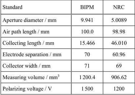
Both free-air chamber standards are of the conventional parallel-plate design. The measuring volume V is defined by the diameter of the chamber aperture and the length of the collecting region. The BIPM air-kerma standard is described in [2] and the changes made to certain correction factors in October 2003 and September 2009 given in [3, 4] and the references therein. Details of the NRC standard are given in [5]. The main dimensions, the measuring volume and the polarizing voltage for each standard are shown in Table 2.
1 For an air temperature T ~ 293 K, pressure P and relative humidity ~50 % in the measuring volume, the correction
for air density involves a temperature correction T / T0, a pressure correction P0/ P and a humidity correction kh= 0.9980. At the BIPM, the factor 1.0002 is included to account for the compressibility of dry air between T ~ 293 K and T0= 273.15 K.
Table 1. Physical constants used in the determination of the air-kerma rate
Constant Value uia
airb 1.293 0 kg m–3 0.000 1
Wair/ e 33.97 J C–1 0.001 5
a uiis the relative standard uncertainty.
b Density of dry air at T0= 273.15 K and P0= 101.325 kPa. Table 2. Main characteristics of the standards
Standard BIPM NRC
Aperture diameter / mm 9.941 5.0089
Air path length / mm 100.0 98.98
Collecting length / mm 15.466 46.010
Electrode separation / mm 70 60.96
Collector width / mm 71 69
Measuring volume / mm3 1 200.4 906.62
Polarizing voltage / V 1 500 1200
4. The transfer instruments
4.1 Determination of the calibration coefficient for a transfer instrument
The air-kerma calibration coefficient NKfor a transfer instrument is given by the relation
tr I K NK (2)
whereK is the air-kerma rate determined by the standard using (1) and Itris the ionization current
measured by the transfer instrument and the associated current-measuring system. The current Itr
is corrected to the reference conditions of ambient air temperature, pressure and relative humidity chosen for the comparison (T = 293.15 K, P = 101.325 kPa and h = 50 %).
To derive a comparison result from the calibration coefficients NK,BIPM and NK,NMI measured,
respectively, at the BIPM and at a national measurement institute (NMI), differences in the radiation qualities must be taken into account. Normally, each quality used for the comparison has the same nominal generating potential at each institute, but the half-value layers (HVLs) might differ. A radiation quality correction factor kQ is derived for each comparison quality Q.
This corrects the calibration coefficient NK,NMIdetermined at the NMI into one that applies at the
‘equivalent’ BIPM quality and is derived by interpolation of the NK,NMI values in terms of
log(HVL). The comparison result at each quality is then taken as
BIPM , NMI , Q NMI , K K K N N k R (3)
In practice, the half-value layers normally differ by only a small amount and kQis close to unity.
4.2 Details of the transfer instruments
Four thin-window parallel-plate ionization chambers belonging to the NRC were used as transfer instruments for the comparison. Their main characteristics are given in Table 3. The reference point for each chamber was taken to be on the axis defined by the entrance window. The reference plane for the PTW chambers was taken to be that defined by the front surface of the casing, while for the Radcal chambers it was taken to be defined by the red line around the casing.
Table 3. Main characteristics of the transfer chambers
Chamber type Radcal 10x5-6M Radcal 10x5-6M PTW 23344 PTW 23344 Serial number 9646 9642 0948 0949 Window / mg cm–2 0.7 0.7 2.5 2.5 Collector diameter / mm 27 27 13 13 Cavity height / mm 9 9 1.5 1.5 Nominal volume / cm3 6 6 0.2 0.2
Potentiala/ V 300 300 200 BIPM, 200 BIPM,
300 NRC 300 NRC
a At the BIPM, the potential was positive and applied to the chamber window, with the collector remaining at virtual ground potential. At the NRC, the potential was negative and applied to the collector with the chamber window remaining at virtual ground potential. In both cases, positive charge was collected.
5. Calibration at the BIPM
5.1 BIPM irradiation facility and reference radiation qualities
The BIPM low-energy x-ray laboratory houses a constant-potential generator and a tungsten-anode x-ray tube with an inherent filtration of 1 mm beryllium. A beryllium filter of thickness 2.16 mm is added (for all radiation qualities) so that the half-value layer (HVL) of the present 10 kV radiation quality matches that of the original BIPM x-ray tube when the same aluminium filter is used. A voltage divider is used to measure the generating potential, which is stabilized using an additional feedback system of the BIPM. Rather than use a transmission monitor, the anode current is measured and the ionization chamber current is normalized for any deviation from the reference anode current. The resulting variation in the BIPM free-air chamber current over the duration of a comparison is normally not more than 3 10–4 in relative terms. The
radiation qualities used in the range from 10 kV to 50 kV are those recommended by the CCRI [1] and are given in Table 4 in ascending HVL from left to right.
The irradiation area is temperature controlled at around 20 °C and is stable over the duration of a calibration to better than 0.1 °C. Two thermistors, calibrated to a few mK, measure the temperature of the ambient air and the air inside the BIPM standard. Air pressure is measured by means of a calibrated barometer positioned at the height of the beam axis. The relative humidity is controlled within the range 47 % to 53 % and consequently no humidity correction is applied to the current measured using transfer instruments.
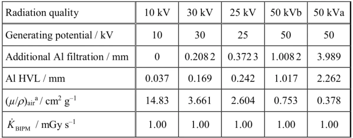
Table 4. Characteristics of the BIPM reference radiation qualities at 500 mm
Radiation quality 10 kV 30 kV 25 kV 50 kVb 50 kVa
Generating potential / kV 10 30 25 50 50 Additional Al filtration / mm 0 0.208 2 0.372 3 1.008 2 3.989 Al HVL / mm 0.037 0.169 0.242 1.017 2.262 (µ/)aira/ cm2g–1 14.83 3.661 2.604 0.753 0.378 BIPM K / mGy s–1 1.00 1.00 1.00 1.00 1.00
a Measured for an air path length of 100 mm (and for the reference distance of 500 mm). 5.2 BIPM standard and correction factors
The reference plane for the BIPM standard was positioned at 500 mm from the radiation source, with a reproducibility of 0.03 mm. The standard was aligned on the beam axis to an estimated uncertainty of 0.1 mm. The beam diameter in the reference plane is 84 mm for all radiation qualities. As the usual reference distance at the NRC is 1 000 mm, additional measurements were made for this distance at the BIPM. For these measurements, an additional tungsten collimator was used to give a beam diameter of around 100 mm at the greater distance.
During the calibration of the transfer chambers, measurements using the BIPM standard were made using positive polarity only. A correction factor of 1.00015 was applied to correct for the known polarity effect in the standard. The leakage current for the BIPM standard, relative to the ionization current, was measured to be less than 1 10–4.
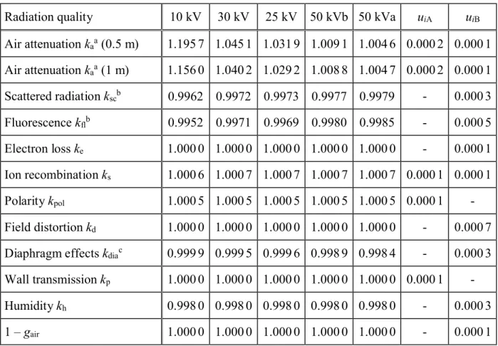
The correction factors applied to the ionization current measured at each radiation quality using the BIPM standard, together with their associated uncertainties, are given in Table 5.
The largest correction at low energies is that due to the attenuation of the x-ray fluence along the air path between the reference plane and the centre of the collecting volume. The correction factor kais evaluated for the reference distance of 500 mm using the measured mass attenuation
coefficients (airgiven in Table 4. For the additional measurements at 1000 mm the measured
air-attenuation corrections are also given. In practice, the values used for ka take account of the
temperature and pressure of the air in the standard at the time of the measurements. Ionization measurements (both for the standard and for transfer chambers) are also corrected for changes in air attenuation arising from variations in the temperature and pressure of the ambient air between the radiation source and the reference plane.
5.3 Transfer chamber positioning and calibration at the BIPM
The reference point for each chamber was positioned in the reference plane with a reproducibility of 0.03 mm. Each transfer chamber was aligned on the beam axis to an estimated uncertainty of 0.1 mm.
The leakage current was measured before and after each series of ionization current measurements and a correction made using the mean value. The relative leakage current for the Radcal transfer chambers was always less than 1 10–4. For the PTW chambers, a typical
leakage current of 2 fA was measured corresponding in relative terms to around 2 10–4for the
Table 5. Correction factors for the BIPM standard
Radiation quality 10 kV 30 kV 25 kV 50 kVb 50 kVa uiA uiB
Air attenuation kaa(0.5 m) 1.195 7 1.045 1 1.031 9 1.009 1 1.004 6 0.000 2 0.000 1 Air attenuation kaa(1 m) 1.156 0 1.040 2 1.029 2 1.008 8 1.004 7 0.000 2 0.000 1 Scattered radiation kscb 0.9962 0.9972 0.9973 0.9977 0.9979 - 0.000 3 Fluorescence kflb 0.9952 0.9971 0.9969 0.9980 0.9985 - 0.000 5 Electron loss ke 1.000 0 1.000 0 1.000 0 1.000 0 1.000 0 - 0.000 1 Ion recombination ks 1.000 6 1.000 7 1.000 7 1.000 7 1.000 7 0.000 1 0.000 1 Polarity kpol 1.000 5 1.000 5 1.000 5 1.000 5 1.000 5 0.000 1 -Field distortion kd 1.000 0 1.000 0 1.000 0 1.000 0 1.000 0 - 0.000 7
Diaphragm effects kdiac 0.999 9 0.999 5 0.999 6 0.998 9 0.998 4 - 0.000 3
Wall transmission kp 1.000 0 1.000 0 1.000 0 1.000 0 1.000 0 0.000 1
-Humidity kh 0.998 0 0.998 0 0.998 0 0.998 0 0.998 0 - 0.000 3
1 – gair 1.000 0 1.000 0 1.000 0 1.000 0 1.000 0 - 0.000 1
a Values for 293.15 K and 101.325 kPa; each measurement is corrected using the air density measured at the time. b Values for kscand kfladopted in October 2003, based on Monte Carlo calculations.
c Correction factor kdiafor diaphragm transmission, scatter and fluorescence adopted September 2009, replacing the
factor kd. See reference [6]
For each of the four transfer chamber and at each radiation quality, a set of seven measurements was made at the usual reference distance of 500 mm, each measurement with integration time 60 s. The relative standard uncertainty of the mean ionization current for each set was always below 2 10–4. An additional relative standard uncertainty component of 5 10–4 is included to
account for the typical reproducibility of calibrations in low-energy x-rays at the BIPM. This procedure (all four chambers at all five radiation qualities) was repeated for the non-standard reference distance of 1 000 mm. The results are shown in Table 8.
6. Calibration at the NRC
6.1 NRC irradiation facility and reference radiation qualities
The low-energy x-ray facility at the NRC comprises a constant-potential low-ripple generator (Glassman PS/PK080N050Y31) and a 100 kV Philips MCN 101 tungsten-anode x-ray tube with an inherent filtration of 1.0 mm beryllium, a focal spot size of 1.5 mm X 1.5 mm and an anode angle of 22o. The generating potential is measured at 3 s intervals using a Park divider calibrated
to 3 parts in 105, which is constant for a given radiation quality to better than 5 V. The X-ray
tube current is stabilized over a wide dynamic range (A to mA) using a feedback system developed at the NRC that controls the beam current. In relative terms, stability over the short term is approximately 5 X 10⁻⁵and long-term stability (0.5 year) around 1 X 10⁻³.
monitor chamber is located 34 cm from the focal spot and consists of five layers of aluminized Mylar, totalling 5.6 mg cm-2 of Mylar and 0.21 mg cm-2of aluminum. The air temperature for
this monitor chamber is measured by a sensor mounted inside the chamber. The X-ray output is switched on and off using a mechanical shutter with a timing uncertainty of approximately 15 ms. The combination of tube current and shutter time serves as a an independent secondary beam monitor. The two beam monitors typically agree at the level of 2 parts in 10-4. The
characteristics of the NRC realization of the CCRI comparison qualities [1] are given in Table 6. The irradiation area is temperature controlled at around 22 °C and is stable over the duration of a calibration to better than 0.1 °C. A calibrated temperature sensor measures the temperature at the position of the instrument being calibrated, and this temperature generally follows the ambient air temperature to within 0.05 oC. The air pressure is measured by means of a calibrated
barometer positioned at the height of the beam axis. The relative humidity is controlled within the range 40 % to 60 % and a humidity correction of nominally 0.998 is calculated based on Fig. 5.14 of ICRU Report 31 [9], and applied to the calibration measurements.
Table 6. Characteristics of the NRC reference radiation qualities
Radiation quality 10 kV 30 kV 25 kV 50 kVb 50 kVa
Generating potential / kV 10 30 25 50 50 Additional Al filtration / mm 0 0.188 0.344 0.993 4.125 Al HVL / mm 0.041 0.166 0.238 1.022 2.252 (µ/)aira/ cm2g–1 12.03 2.920 2.005 0.5889 0.3472 NRC K / mGy s–1 0.26 0.20 0.35 0.27 0.18
a Measured for an air path length of 98.98 mm (and for the reference distance of nominally 1000 mm).
6.2 NRC standard and correction factors
The reference plane for the NRC standard was positioned at 1 000 mm from the radiation source, with a reproducibility of 0.1 mm. The standard was aligned on the beam axis to an estimated uncertainty of 0.2 mm. The beam diameter in the reference plane is approximately 90 mm for all radiation qualities. Because the usual reference distance at the BIPM is 500 mm, additional measurements were made for this distance at the NRC. For these measurements, no change was made to the collimation and so the beam diameter was nominally 45 mm (significantly smaller than the BIPM field diameter at this distance).
During the calibration of the transfer chambers, measurements using the NRC standard were made using positive polarity only. A correction factor kpol was not applied as the polarity effect
in the standard measured for each radiation quality was negligible. The relative leakage current for both the Radcal and PTW chambers was was measured to be less than -4 10–4.
The correction factors applied to the ionization current measured at each radiation quality using the NRC standard, together with their associated uncertainties, are given in Table 7.
The correction factors ka are evaluated using the measured air-attenuation coefficients given in
Table 6. In practice, the values used for ka take account of the temperature and pressure of the
transfer chambers) are also corrected for variations in the temperature and pressure of the ambient air between the radiation source and the reference plane.
6.3 Transfer chamber positioning and calibration at the NRC
The reference point for each chamber was positioned in the reference plane with a reproducibility of 0.1 mm. Alignment on the beam axis was to an estimated uncertainty of 0.2 mm.
The leakage current was measured before and after each series of ionization current measurements and a correction made using the mean value. The relative leakage current for the Radcal chambers was typically 1 10–4and for the PTW chambers around 2 10–4.
For each of the four transfer chamber and at each radiation quality, three or four sets of at least 10 measurements was made at the usual reference distance of 1000 mm, each measurement with integration time of 30 to 60 seconds for the Radcal chambers depending upon beam quality, and 60 to 120 seconds for the PTE chambers depending up on beam quality. The relative standard uncertainty of the mean ionization current for each set was around 2 10–4. This procedure was
repeated (all four chamber at all five radiation qualities) for the non-standard reference distance of 500 mm. The results are shown in Table 8.
Table 7. Correction factors for the NRC standard
Radiation quality 10 kV 30 kV 25 kV 50 kVb 50 kVa uiA uiB
Air attenuation kaa(0.5 m) 1.217 5 1.043 4 1.029 9 1.010 1 1.005 0 0.0002 0.0007 Air attenuation kaa(1 m) 1.163 8 1.043 9 1.031 0 1.010 0 1.005 0 0.0002 0.0007 Scattered radiation ksc 0.995 3 0.995 6 0.995 7 0.996 8 0.997 4 - 0.0010 Fluorescence kflc 1.0000 1.0000 1.0000 1.0000 1.0000 - -Electron loss ke 1.000 0 1.000 0 1.000 0 1.000 0 1.000 0 - 0.0007 Ion recombination ks 1.000 7 1.000 7 1.000 7 1.000 7 1.000 7 0.0001 0.0002 Polarity kpol 1.0000 1.0000 1.0000 1.0000 1.0000 0.0001 -Field distortion kd 1.0000 1.0000 1.0000 1.0000 1.0000 - 0.0015 Aperture transmission klc 1.0000 1.0000 1.0000 1.0000 1.0000 - -Wall transmission kp 1.0000 1.0000 1.0000 1.0000 1.0000 - 0.0002 Humidity khb 0.998 0 0.998 0 0.998 0 0.998 0 0.998 0 - 0.0003 1 – gair 1.000 0 1.000 0 1.000 0 1.000 0 1.000 0 - 0.0001
a Values for 295.15 K and 101.325 kPa; each measurement is corrected using the air density measured at the time. b A humidity correction of nominally 0.998 was applied during each measurement based on the measured humidity at the time, as recommended in ICRU Report 31 [9]
7. Additional considerations for transfer chamber calibrations
7.1 Ion recombination, polarity, radial non-uniformity and field size
As can be seen from Tables 4 and 6, the air-kerma rates are very closely matched at the two laboratories and so no corrections are applied for ion recombination. Each transfer chamber was used with the same polarity at each institute and so no corrections are applied for polarity effects in the transfer chambers.
No correction krn,tr is applied at either laboratory for the radial non-uniformity of the radiation
field. For a chamber with collector radius 10 mm, the correction factor for the BIPM reference field is around 1.0008 and this effect is likely to cancel to some extent at the two laboratories. A relative standard uncertainty of 5 10–4is introduced for this effect.
It is of note that the field diameter of 47 mm at the NRC (at 500 mm) is much smaller than that of 84 mm for the same distance at the BIPM. Measurements at the BIPM over a range of field sizes have shown that under these conditions the calibration coefficient can change by over 1 % for the PTW-23344 chamber-type at the 50 kV(a) quality. For the Radcal chamber type, the effect is much smaller. The effect of this on the present comparison is assessed in the analysis of the results for the different chambers at difference distances presented in Section 8.
7.2 Radiation quality correction factors kQ
As noted in Section 4.1, slight differences in radiation qualities might require a correction factor
kQ. However, from Tables 4 and 6 it is evident that the radiation qualities at the BIPM and at the
NRC are very closely matched in terms of HVL and so the correction factor kQ is taken to be
unity for all qualities, with a negligible uncertainty.
8. Comparison results
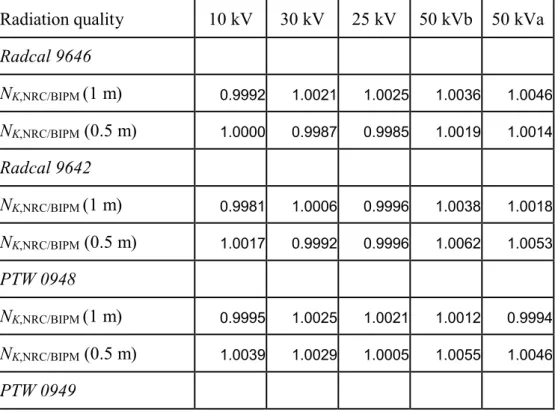
As the transfer chambers used for this comparison will be used for other comparisons in the future, only the ratios of the calibration coefficients NK,NRC/ NK,BIPMdetermined at the NRC and
at the BIPM are given in Table 8.
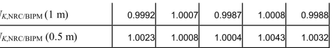
Table 8. Ratios of calibration coefficients NK,NRC/ NK,BIPMfor the transfer chambers
Radiation quality 10 kV 30 kV 25 kV 50 kVb 50 kVa
Radcal 9646 NK,NRC/BIPM (1 m) 0.9992 1.0021 1.0025 1.0036 1.0046 NK,NRC/BIPM(0.5 m) 1.0000 0.9987 0.9985 1.0019 1.0014 Radcal 9642 NK,NRC/BIPM (1 m) 0.9981 1.0006 0.9996 1.0038 1.0018 NK,NRC/BIPM(0.5 m) 1.0017 0.9992 0.9996 1.0062 1.0053 PTW 0948 NK,NRC/BIPM (1 m) 0.9995 1.0025 1.0021 1.0012 0.9994 NK,NRC/BIPM(0.5 m) 1.0039 1.0029 1.0005 1.0055 1.0046 PTW 0949
0,996 0,998 1,000 1,002 1,004 1,006 1,008 1,010 -1,6 -1,1 -0,6 -0,1 0,4 log(HVL) NK ,N R C / NK ,B IP M Radcal 9646 0.5 m Radcal 9646 1 m Radcal 9642 0.5 m Radcal 9642 1 m PTW 0948 0.5 m PTW 0948 1 m PTW 0949 0.5 m PTW 0949 1 m NK,NRC/BIPM (1 m) 0.9992 1.0007 0.9987 1.0008 0.9988 NK,NRC/BIPM(0.5 m) 1.0023 1.0008 1.0004 1.0043 1.0032
The results are presented graphically in Figure 1 as the ratios NK,NRC/ NK,BIPM for each transfer
chamber at each distance, as a function of log(HVL). The results show a significant spread, the relative standard deviation of the distribution ranging from 1.4 10–3 for the 30 kV quality to
2.4 10–3 for the 50 kVa quality. This is significantly greater than the statistical standard
uncertainty of each calibration coefficient. However, no clear trends emerge, except perhaps that at 10 kV the results for 1 m (dotted lines) are lower than those for 0.5 m (solid lines). This might be related to the attenuation correction; it is of note that the change in kabetween 0.5 m and 1 m
is quite different at the two laboratories. The field size effect for the PTW chambers (in red) at 50 kV, anticipated in Section 7.1, appears to have no significant effect on the results.
Figure 1. Comparison results NRC/BIPM for the four transfer chamber at two reference distances.
Consequently, the best estimate of the comparison result RK,NRC for each radiation quality is
considered to be the mean value. These values are given in Table 9 along with the standard uncertainty of the distribution, dist, and the standard uncertainty of each mean value, mean. Also
given in the table are the results of the previous, direct comparison of the NRC and BIPM standards [5], revised for the published changes made to the BIPM standard in 2003 [3] and in 2009 [4]. The results and combined uncertainties are discussed in Section 10.
Table 9. Combined comparison results
Radiation quality 10 kV 30 kV 25 kV 50 kVb 50 kVa
RK,NRC 1.000 3 1.001 3 1.000 7 1.004 3 1.003 3
dist 0.001 9 0.001 5 0.001 4 0.002 0 0.002 4
mean 0.000 7 0.000 5 0.000 5 0.000 7 0.000 8
Previous result for RK,NRC 1.003 5 1.002 0 - - 1.001 1
9. Uncertainties
The uncertainties associated with the primary standards are listed in Table 10, and those for the transfer chamber calibrations in Table 11. The combined uncertainty for the comparison results
RK,NRC, presented in Table 12, includes a component of 1.2 parts in 103arising from the spread of
the results for the different transfer chambers and distances, a compromise value falling somewhere between meanand distof Table 9.
Table 10. Uncertainties associated with the standards
Standard BIPM NRC
Relative standard uncertainty uiA uiB uiA uiB
Ionization current 0.000 2 0.000 2 0.0003 0.0003
Volume 0.000 3 0.000 5 0.0001 0.0004
Positioning 0.000 1 0.000 1 0.0002 0.0001
Correction factors (excl. kh) 0.000 3 0.001 0 0.0003 0.0022
Humidity kh - 0.000 3 - 0.000 3
Physical constants - 0.001 5 - 0.001 5
K 0.0005 0.001 9 0.0005 0.0027
Table 11. Uncertainties associated with the calibration of the transfer chambers
Institute BIPM NRC
Relative standard uncertainty uiA uiB uiA uiB
K 0.000 5 0.001 9 0.0004 0.0026
Positioning of transfer chamber 0.000 1 - 0.0002 0.0002
Itr 0.000 2 0.000 2 0.0002 0.0002
-NK 0.000 7 0.001 9 0.0008 0.0028
The combined standard uncertainty ucof the comparison result takes into account correlation in
the type B uncertainties associated with the physical constants and the humidity correction. Correlation in the values for the correction factor kscat the two laboratories, derived from Monte
Carlo calculations in each laboratory, are taken into account in an approximate way by assuming half of the uncertainty value at each laboratory. This is consistent with the analysis of the results of BIPM comparisons in low-energy x-rays in terms of degrees of equivalence described in [8].
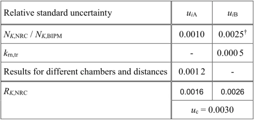
Table 12. Uncertainties associated with the comparison results
Relative standard uncertainty uiA uiB
NK,NRC/ NK,BIPM 0.0010 0.0025†
krn,tr - 0.000 5
Results for different chambers and distances 0.001 2
-RK,NRC 0.0016 0.0026
uc= 0.0030
† Takes account of correlation in type B uncertainties.
10. Discussion
The comparison results presented in Table 9 show general agreement at the level of 2 parts in 103, which is within the combined relative standard uncertainty of 0.0030. A slight trend with
radiation quality is observed, which might be due in part to the fact that no diaphragm correction
kdia is applied to the NRC standard. The implementation of a correction for fluorescence, kfl, for
the NRC standard would also influence the dependence of the comparison results on radiation quality. Interestingly, although the agreement with the results of the previous comparison is reasonable, the slight trend with radiation quality is reversed. This might be related to the fact that the present comparison employs transfer chambers while the previous comparison was direct. While the use of transfer chambers might introduce more uncertainty in the comparison of the primary standards, useful information is gained on the reproducibility of calibration coefficients, particularly in the present work with the exceptional use of four transfer instruments and two calibration distances.
11. Degrees of Equivalence
The analysis of the results of BIPM comparisons in low-energy x-rays in terms of degrees of equivalence is described in [8]. Following a decision of the CCRI, the BIPM determination of the air-kerma rate is taken as the key comparison reference value, for each of the CCRI radiation qualities. It follows that for each laboratory i having a BIPM comparison result xiwith combined
standard uncertainty ui, the degree of equivalence with respect to the reference value is the
relative difference Di= (Ki– KBIPM,i) / KBIPM,i= xi– 1 and its expanded uncertainty Ui= 2 ui.
The results for Di and Ui, expressed in mGy/Gy and including those of the present comparison,
are shown in Table 13 and in Figure 12.
The degree of equivalence of laboratory i with respect to each laboratory j that has taken part in a BIPM comparison is the difference Dij= Di– Dj= xi– xjand its expanded uncertainty Uij= 2 uij.
The combined standard uncertainty uijis mainly the combined uncertainty of the air-kerma rate
removed, notably that arising from ke, kscand kfl. As described in [6], if correction factors based
on Monte Carlo calculations are used by both laboratories, or by neither, then half the uncertainty value is taken for each factor. Note that the uncertainty of the BIPM determination of air-kerma rate does not enter in uij, although the uncertainty arising from the comparison
procedure is included. The results for Dij and Uij when j represents the NRC, are also given in
Table 13 and in Figure 3. Note that the data presented in the tables, while correct at the time of publication of the present report, become out of date as laboratories make new comparisons with the BIPM. The formal results under the CIPM MRA are those available in the BIPM key comparison database.
References
[1] BIPM, Qualités de rayonnement, CCEMRI(I), 1972, R15.
[2] BOUTILLONM., Mesure de l’exposition au BIPM dans le domaine des rayons X de 100 à 250 kV, 1978, Rapport BIPM-78/3.
[3] BURNSD.T., Changes to the BIPM primary air-kerma standards for x-rays, 2004,
Metrologia 41, L3.
[4] BURNSD.T., KESSLER C. and ALLISYP.J., Re-evaluation of the BIPM international standards for air kerma in x-rays, 2009, (in press)
[5] BOUTILLON M., HENRY W.H. and LAMPERTI P.J., Comparison of exposure standards in the 10-50 kV x-ray region, 1969, Metrologia 5, 1-11.
[6] BURNSD.T.and KESSLER C, Diaphragm correction factors for free-air chamber standards for air-kerma in x-rays, 2009, Phys. Med. Biol. 54 2737–2745
[7] NIST XCOM online database: http://physics.nist.gov/PhysRefData/Xcom/Text/XCOM.html; October 2004
[8] BURNSD.T., Degrees of equivalence for the key comparison BIPM.RI(I)-K3 between national primary standards for medium-energy x-rays, 2003, Metrologia 40 Technical
Supplement, 06036.
[9] International Commission on Radiation Units and Measurements, ICRU Report 31: Average Energy Required to Produce an Ion Pair, 1979, 31.