HAL Id: tel-01311262
https://tel.archives-ouvertes.fr/tel-01311262
Submitted on 4 May 2016HAL is a multi-disciplinary open access archive for the deposit and dissemination of sci-entific research documents, whether they are pub-lished or not. The documents may come from teaching and research institutions in France or abroad, or from public or private research centers.
L’archive ouverte pluridisciplinaire HAL, est destinée au dépôt et à la diffusion de documents scientifiques de niveau recherche, publiés ou non, émanant des établissements d’enseignement et de recherche français ou étrangers, des laboratoires publics ou privés.
Thermodynamic study of the invessel corium
-Application to the corium/concrete interaction
Andrea Quaini
To cite this version:
Andrea Quaini. Thermodynamic study of the in-vessel corium - Application to the corium/concrete interaction. Materials. Université Grenoble Alpes, 2015. English. �NNT : 2015GREAI061�. �tel-01311262�
THÈSE
Pour obtenir le grade de
DOCTEUR DE L’UNIVERSITÉ GRENOBLE ALPES
Spécialité : Matériaux, Mécanique, Génie civil, ElectrochimieArrêté ministériel : le 6 janvier 2005 - 7 août 2006
Présentée par
Andrea QUAINI
Thèse dirigée par Fiqiri HODAJ et
codirigée par Christine GUÉNEAU et Stéphane GOSSÉ préparée au sein du Laboratoire de Modélisation, de
Thermodynamique et de Thermochimie du CEA Saclay et au Laboratoire SIMAP
dans l’École Doctorale IMEP-2
Étude thermodynamique du
corium en cuve - Application à
l'interaction corium/béton
Thèse soutenue publiquement le 03 Novembre 2015, devant le jury composé de :
Prof. Hans Juergen SEIFERT
Directeur de Recherche au KIT de Karlsruhe, Rapporteur
Dr. Daniel NEUVILLE
Directeur de Recherche à l’IPGP de Paris, Rapporteur
Dr. Bengt HALLSTEDT
Chercheur au RWTH de l’Université d’Aachen, Examinateur
Dr. Marc BARRACHIN
Ingénieur chercheur à l’IRSN, Examinateur
Dr. Dario MANARA
Chercheur au JRC-ITU, Invité
Dr. Christine GUÉNEAU
Ingénieur chercheur au CEA, Examinateur
Dr. Stéphane GOSSÉ
Ingénieur chercheur au CEA, Examinateur
Prof. Fiqiri HODAJ
Professeur à Grenoble INP, Directeur de thèse Prof. Rudy KONINGS
- 3 -
In this house we obey the laws of thermodynamics! H.J.S.
- 5 -
Acknowledgments
The work presented in this manuscript was performed to obtain the PhD diploma at the Grenoble INP under the direction of Prof. Fiqiri Hodaj. This work has been carried out at the Laboratoire de Modélisation, de Thermodynamique et de Thermochimie (LM2T), CEA Saclay. I would like to thank the Heads of this laboratory: Jean-Luis Fleche and Clara Desgranges. I would also like to thank Philippe Prené and Fabrice Legendre, Heads of the SCCME Unit at the CEA Saclay.
I wish to thank all the members of my PhD thesis jury, in particular my committee members, Prof. Hans Jürgen Seifert and Dr. Daniel Neuville, for the brilliant comments and questions during the defence.
During the past three years I had the opportunity to work with wonderful people. I warmly thank my supervisors, Stéphane Gossé and Christine Guéneau for their continuous support and the fruitful scientific discussion. They introduced me to CALPHAD and they have taught me a lot on material science!
I would also like to thank Thierry Alpettaz and Eric Lizon a Lugrin for their precious help during the design of the ATTILHA setup. Their enormous technical backgrounds have been essential for the success in the development of this novel experimental setup.
During my thesis I had also the chance to perform experiments at the JRC-ITU under the supervision of my friend Dario Manara: thank you for having willingly transmitted me your knowledge on laser heating technique and material science. I also thank the TALISMAn project committee for funding these activities at the JRC-ITU.
I also thank all the people who contributed with their work to this thesis: Didier Bossu, Pierre-François Giroux, Sylvie Poissonnet, Patrick Bonnaillie, Michel Tabarant, Emmanuelle Brackx, Fabrice Gamboa and Laurent Risser.
A special thanks to my parents, for their continuous support during my studies.
I would also thank all my friends for providing me support and friendship! In particular, Tia, Fede and Andre… far away but so close!
The last part of this section is dedicated to my Crapin, Irene. You have been the person who supported me the most all along the past three years, during my good and bad times. You always have had faith in me, even when I didn’t. I thank you deeply for staying by my side during the most difficult moments of this adventure called PhD. Without you, this wouldn’t have been possible.
- 7 -
Étude thermodynamique du corium en cuve – Application à l’interaction corium/béton
Résumé :
Lors d’un accident grave dans un réacteur nucléaire à eau pressurisée, le combustible nucléaire va réagir avec le gaines en Zircaloy, les absorbants neutroniques et les structures métalliques environnantes pour former un mélange partiellement ou complètement fondu. Ce cœur fondu peut ensuite interagir avec la cuve en acier du réacteur pour former un mélange appelé corium en cuve. Par la suite, le corium peut percer la cuve et venir se déverser sur le radier en béton en-dessous du réacteur. En fonction du scénario considéré, le corium qui va réagir avec le béton peut être constitué soit d’une seule phase liquide oxyde ou de deux liquides, métallique et oxyde. L’objectif de la thèse est l’étude de la thermodynamique du corium en cuve, prototypique U-Pu-Zr-Fe-O. L’approche utilisée est basée sur la méthode CALPHAD, qui permet de développer un modèle thermodynamique sur ce système complexe à partir de données expérimentales thermodynamiques et de diagramme de phases. Des traitements thermiques sur le système O-U-Zr ont permis de mesurer deux conodes dans la lacune de miscibilité à l’état liquide à β567 K. De plus, des températures de liquidus ont été mesurées sur trois échantillons riches en Zr, en utilisant le montage de chauffage laser de l’ITU. Par la même méthode, des températures de solidus ont été obtenues sur le système UO2-PuO2-ZrO2. L’influence de l’atmosphère réductrice ou oxydante sur le comportement à
la fusion de ce système a été étudiée pour la première fois. Les résultats montrent que la stœchiométrie en oxygène de ces oxydes dépend fortement du potentiel d’oxygène et de la composition en métal des échantillons. La lacune de miscibilité à l’état liquide a également été mise en évidence dans un échantillon U-O-Zr-Fe. L’ensemble de ces nouvelles données expérimentales avec celles de la littérature a permis de développer le modèle sur le système U-Pu-Zr-Fe-O. Pour tous les échantillons, des calculs de chemin de solidification avec ce modèle ont servi à interpréter les microstructures de solidification observées. Un bon accord est obtenu entre les calculs et les résultats expérimentaux. Des traitements thermiques sur deux échantillons de corium hors cuve ont permis de montrer l’influence de la composition du béton sur la nature des phases liquides formées à haute température. Les microstructures de solidification ont été interprétées à l’aide de calculs avec la base de données TAF-ID. En parallèle, un nouveau montage expérimental appelé ATTILHA, utilisant la lévitation aérodynamique et le chauffage laser, a été conçu et développé pour mesurer des données de diagramme de phase à haute température. Ce montage a été validé avec des systèmes oxydes bien connus. De plus, cette méthode a permis d’observer in-situ à l’aide de la caméra infra-rouge la formation de la lacune de miscibilité à l’état liquide dans le système O-Fe-Zr lors de l’oxydation d’une bille d’alliage Fe-Zr. La prochaine étape du développement est la nucléarisation du montage pour effectuer des mesures sur des échantillons contenant de l’uranium. La mise en place d’une caméra ultra rapide (5000 Hz) pour l’étude de propriétés thermo-physiques de mélanges de corium en cuve et hors cuve est également envisagée. La synergie entre le développement de ces outils expérimentaux et de calcul devrait permettre d’améliorer la description thermodynamique du corium et des codes de calcul sur les accidents graves utilisant ces données thermodynamiques.
Mots clés :
Thermodynamique, Système U-Pu-Zr-Fe-O, CALPHAD, Chauffage laser, Interaction corium/béton
- 8 -
Thermodynamic study on the in-vessel corium – Application to the corium/concrete
interaction
Abstract :
During a severe accident in a pressurised water reactor, the nuclear fuel can interact with the Zircaloy cladding, the neutronic absorber and the surrounding metallic structure forming a partially or completely molten mixture. The molten core can then interact with the reactor steel vessel forming a mixture called in-vessel corium. In the worst case, this mixture can pierce the vessel and pour onto the concrete underneath the reactor, leading the formation of the ex-vessel corium. Furthermore, depending on the considered scenario, the corium can be formed by a liquid phase or by two liquids, one metallic the other oxide. The objective of this thesis is the investigation of the thermodynamics of the prototypic in-vessel corium U-Pu-Zr-Fe-O. The approach used during the thesis is based on the CALPHAD method, which allows to obtain a thermodynamic model for this complex system starting from phase diagram and thermodynamic data. Heat treatments performed on the O-U-Zr system allowed to measure two tie-lines in the miscibility gap in the liquid phase at 2567 K. Furthermore, the liquidus temperatures of three Zr-enriched samples have been obtained by laser heating in collaboration with ITU. With the same laser heating technique, solidus temperatures have been obtained on the UO2-PuO2-ZrO2 system. The influence of the reducing or oxidising on
the melting behaviour of this system has been studied for the first time. The results show that the oxygen stoichiometry of these oxides strongly depends on the oxygen potential and on the metal composition of the samples. The miscibility gap in the liquid phase of the U-Zr-Fe-O system has been also observed. The whole set of experimental results with the literature data allowed to develop the thermodynamic model of the U-Pu-Zr-Fe-O system. Solidification path calculations have been performed for all the investigated samples to interpret the microstructures of the solidified samples. A good accordance has been obtained between calculation and experimental results. Heat treatments on two ex-vessel corium samples showed the influence of the concrete composition on the nature of the liquid phases formed at high temperature. The observed microstructures have been interpreted by means of calculation performed with the TAF-ID database. In parallel, a novel experimental setup named ATTILHA based on aerodynamic levitation and laser heating has been conceived and developed to obtain high temperature phase diagram data. This setup has been validated on well-known oxide systems. Furthermore, this technique allowed to observe in-situ, by using an infrared camera, the formation of a miscibility gap in the liquid phase of the O-Fe-Zr system by oxidation of a Fe-Zr sample. The next step of the development will be the nuclearization of the apparatus to investigate U-containing samples. The implementation of a very fast visible camera (5000 Hz) to investigate the thermo-physical properties of in-vessel and ex-vessel corium mixtures is also underway. The synergy between the development of experimental and calculation tools will allow to improve the thermodynamic description of the corium and the severe accident code using thermodynamic input data.
Keywords :
Thermodynamics, U-Pu-Zr-Fe-O system, CALPHAD, Laser heating, Corium/concrete interaction
- 9 -
Contents
1 Introduction and Context ... 13
1.1 Severe accident in LWR- -The INES scale ... 14
1.1.1 Three Mile Island unit 2 – TMI-2 (1979) ... 15
1.1.2 Fukushima Daiichi (2011) ... 16
1.1.3 Consideration on severe accidents – EPR design ... 17
1.2 PWR core degradation phenomena ... 18
1.2.1 In-vessel corium retention ... 19
1.2.2 Ex-vessel corium retention ... 22
1.3 Concluding remarks ... 23
1.4 References ... 25
2 Critical review of literature data ... 27
2.1 Thermodynamic and phase data on in-vessel corium systems .... 27
2.1.1 O-U-Zr system ... 27 2.1.2 UO2-ZrO2 system... 33 2.1.3 O-Fe-U system... 37 2.1.4 O-Fe-Zr system ... 39 2.1.5 O-Pu-Zr system ... 41 2.1.6 O-Fe-U-Zr system ... 42 2.1.7 O-Pu-U-Zr system ... 43 2.1.8 Summary... 44
2.2 Molten Corium-Concrete interaction large scale experiments .... 44
2.2.1 Degradation of fuel bundles and in-vessel retention ... 45
2.2.2 Fission products release ... 46
2.2.3 Molten corium-water interaction ... 46
2.2.4 Molten corium-concrete interaction MCCI ... 48
2.2.5 The PLINIUS facility ... 49
2.2.6 Summary... 53
2.3 Conclusions ... 54
2.4 References ... 55
3 Thermodynamics of the in-vessel corium: experimental study ... 59
3.1 Methodology ... 59
3.2 Experimental study ... 60
3.2.1 O-U-Zr system ... 61
3.2.1.1 Heat treatments ... 61
3.2.1.3 Laser heating experiments ... 76
3.2.2 O-Fe-Zr system ... 86
3.2.3 UO2-PuO2-ZrO2 system ... 87
3.2.3.1 Sample preparation and characterisation ... 88
3.2.3.2 Laser heating results ... 89
3.2.3.3 Discussion... 92
- 10 -
3.3 Conclusions ... 97
3.4 References ... 99
4 Thermodynamics of the in-vessel corium: modelling and calculations ... 103
4.1 Thermodynamic modelling ... 104
4.1.1 O-U-Zr system ... 104
4.1.1.1 UO2-ZrO2 system... 104
4.1.1.2 O-U-Zr isothermal sections at high temperatures (2273, 2567 and 3223 K) ... 105
4.1.1.3 O-U-Zr isothermal sections at low temperatures (1373 and 1673 K) ... 111
4.1.1.4 Summary... 115
4.1.2 O-Fe-Zr system ... 115
4.1.2.1 ZrO2-FeO section... 116
4.1.2.2 ZrO2-Fe2O3 section ... 116
4.1.2.3 O-Fe-Zr isothermal section at 1473 K ... 117
4.1.2.4 Calculated O-Fe-Zr isothermal sections ... 118
4.1.2.5 Summary... 118
4.1.3 O-Fe-U ... 119
4.1.3.1 UO2-FeO1.1 section ... 120
4.1.3.2 Calculated O-Fe-U isothermal sections ... 121
4.1.3.3 Summary... 121
4.1.4 O-Pu-U-Zr system ... 122
4.1.4.1 PuO2-ZrO2 system ... 122
4.1.4.2 UO2-PuO2-ZrO2 system ... 123
4.2 Solidification path calculations ... 124
4.2.1 O-U-Zr samples ... 124
4.2.1.1 Sample OUZr_1... 124
4.2.1.2 Sample OUZr_3... 127
4.2.1.3 Sample OUZr_7... 130
4.2.1.4 Summary... 131
4.2.2 Laser heating results on the UO2-PuO2-ZrO2 system .. 132
4.2.2.1 Solidification path of sample U48P3Z49 ... 133
4.2.2.2 Solidification path of sample P50Z50 ... 134
4.2.2.3 Solidus and liquidus surfaces calculation ... 135
4.2.2.4 Structural analysis on as-synthetized samples . 136 4.2.2.5 Structural analysis after melting ... 140
4.2.2.6 Summary... 140
4.2.3 In-vessel corium investigation ... 141
4.2.3.1 Oxide liquid (Liquid 2) ... 142
4.2.3.2 Metallic liquid (Liquid 1) ... 145
4.2.3.3 Summary... 148
4.3 Conclusions ... 148
- 11 -
5 Experimental and calculation results on ex-vessel corium ... 153
5.1 Experimental results ... 153
5.1.1 Sample preparation and characterisation ... 154
5.1.2 CORIUM_1 ... 154
5.1.3 CORIUM_2 ... 156
5.1.4 Summary... 161
5.2 Solidification path calculations ... 161
5.2.1 TAF-ID database ... 161 5.2.2 Results ... 162 5.2.2.1 CORIUM_1 ... 162 5.2.2.2 CORIUM_2 ... 164 5.3 Conclusions ... 166 5.4 References ... 167
6 ATTILHA experimental setup ... 170
6.1 Apparatus description ... 170
6.1.1 Bi-chromatic pyrometer... 170
6.1.2 HgCdTe detector ... 172
6.1.3 Infrared camera ... 174
6.1.3.1 Calibration of the infrared camera ... 174
6.1.3.2 Infrared images processing ... 176
6.2 Validation of the experimental setup ... 177
6.2.1 Al2O3... 178
6.2.2 Al2O3-ZrO2 ... 182
6.2.3 Exploration of the liquid miscibility gap in O-Fe-Zr .. 188
6.3 Conclusions and perspectives ... 193
6.4 References ... 194
Conclusions and perspectives ... 195
Appendix A ... 199 Appendix B... 211 Appendix C ... 221 Appendix D ... 231 Appendix E... 239 Appendix F ... 241 Résumé ... 249
- 13 -
Chapter 1
– Introduction and Context
The 435 operating nuclear reactors represent 11 % of the world electricity production [1]. These nuclear power plants are competitive thanks to their low operational costs. Moreover, since the fuel represents only a small fraction of the nuclear electricity cost, fluctuations of the uranium price barely affect the competitive position of the nuclear option. From the environmental point of view, the nuclear option is considered as a low-emission CO2
alternative. In this framework, the nuclear security is of paramount importance, especially considering the potential effects of a severe accident.
During the nominal operation of a Light Water Reactor (LWR), the radioactive products (nuclear fuel, fission products, transuranium elements) are separated from the environment by three barriers: the fuel cladding, the primary circuit and the containment reactor vessel (Figure 1).
Figure 1: Scheme of a Pressurised Water Reactor (PWR). The numerical labels remind the three radiological barriers: (1) fuel cladding, (2) primary circuit and (3) containment reactor vessel A nuclear accident may be defined as the non-intentional event that significantly reduces, under the accepted design level, the integrity of one or more barriers. This kind of situations does not necessarily imply a danger and it can be corrected before start again the normal operation of the reactor. However, an accident may turn into a severe accident if the implemented corrections are not sufficient to re-establish the nominal functioning conditions of the Nuclear Power Plant (NPP). For example, if the residual heat of decay produced by the reactor core (even in condition of reactor shut-down) is not removed by the reactor coolant, the temperature of the fuel assembly can rapidly increase.
Generally, during the nominal functioning of a Pressurised Water Reactor (PWR), the temperature at the centre of the fuel pin does not exceed 1373 K. If the cooling system fails, the heat produced by the radioactive decay is uniformly redistributed in the fuel pin leading to
- 14 -
a rise of its superficial temperature. As a direct consequence, the temperature of the fuel cladding may pass from 573 K to 973-1073 K in few seconds.
1.1 Severe accidents in LWR - The INES scale
A severe accident may be originated by internal or external causes. The internal events may be malfunctioning, plant ruptures or mistakes of the operators, whilst the external events are mostly of natural origin (earthquakes, tornados, flooding) but they can also be plane crashes, missiles attacks or flammable gas explosions. The International Nuclear and Radiological Event Scale INES [2] is a tool for a rapid communication between media, population and the nuclear community on the safety significance of events concerning nuclear installations. The INES classifies these out-of-nominal functioning events in seven categories. In Figure 2 the INES is reported.
Figure 2: The International Nuclear and Radiological Event Scale [2]
Each step is separated by an order of magnitude from the previous and following in terms of its effect. In the history of nuclear energy, some events occurred with different levels of gravity. A list of the
most severe accidents is reported in Table 1.
Event Reactor design Description INES
level Windscale, UK
(1957) B-Reactor, AGR
Pile 1 caught fire leading to the spread of a considerable quantity of fission products, especially iodine-131, in the environment.
5 Three Mile
Island, USA (1979)
PWR Partial melt-down of the reactor core 5
Chernobyl,
URSS (1986) RBMK
Partial destruction of the nuclear core. Large degradation of the nuclear fuel. Large release of radioactive materials in the environment due to a graphite fire.
7
Fukushima,
Japan (2011) BWR
Meltdown of the units 1, 2 and 3 cores of the NPP. Considerable release of radioactive material in the sea and in the surrounding of the NPP
7 Table 1: INES level of the most severe accidents in nuclear installations.
AGR=Advanced Gas Reactor; PWR=Pressurised Water Reactor;
RBMK=Reaktor Bolshoy Moshchnosti Kanalnyy (High Power Channel-type Reactor); BWR=Boiling Water Reactor; NPP=Nuclear Power Plant
- 15 -
The Three Mile Island accident (Table 1) led to severe damages to the reactor but to a limited radioactive release in the environment (1% of the background radiation dose). Windscale caused a relevant release of radioactive material leading the authorities to partially set up the emergency plan to limit the effects on the population health.
During the Chernobyl and Fukushima accidents, a more critical situation was faced. In the case of the Chernobyl accident the core was destroyed and the radioactive materials were spread in the air reaching most of the radioactivity monitoring stations in Europe. It is estimated that 3.5 % of the fuel was ejected from the reactor. All the radioactive noble gases, 33 % of the core inventory of caesium and 50 % of iodine-131 were released as well [3]. The most recent severe accident occurred the 11th March, 2011 at the Fukushima Daiichi nuclear power plant. Three of the four units at the Fukushima Daiichi NPP experienced core melt-down and release of radioactive materials.
In the following a brief description of the progression of the Three Miles Island and Fukushima accidents will be given. These severe accidents are of particular interest for the present study because represent two accidental scenarios occurred in LWRs. Even if the Chernobyl accident can be considered as the most serious, its progression will not be reported. In fact, the accidental phenomenology is different compared with the LWRs’ one. A detailed description of the accidental progression of Chernobyl accident can be found elsewhere [3].
1.1.1 Three Mile Island unit 2 – TMI-2 (1979)
The Three Mile Island NPP consists of 2 units equipped with PWRs. The reactor of the unit 2 had a thermal power of 2272 MWth and an electrical power of 880 MWe.
The unit 2 (TMI-2) was operating at 97% of the nominal maximum power when the accident happened. During maintenance operations performed some days before, the valves of the Automatic Feedwater System (AFS) were closed. This system allows removing the heat of decay from the reactor in the case of an emergency shut-down of the reactor. At 4:00 am on 28th March the feedwater flow to the steam generator was lost (event that can occur 2 to 3 times per year in a plant such as TMI-2 [3]). Because of the sudden loss of the heat removal, the pressure began to rise in the primary system up to 163.8 bars. The Pilot Operator Relief Valve (PORV) on the pressuriser opened and the reactor was shut down inserting the control rods. At 153 bars the PORV failed to close leading the system pressure continue dropping. The high pressure Emergency Core Cooling System (ECCS) automatically turned on when the pressure reached 111.8 bars. After a short time the operator thought that the primary system was full of water and to prevent the overfilling of the vessel he turned the ECCS off. This procedure led the remaining water in the reactor to evaporate: the core was in direct contact with water vapour leading to a dramatic overheating of the fuel. The cladding started a strong exothermic oxidation reaction that caused a rapid rise in temperature. Without any active cooling system the fuel melted and reacted first with the partially oxidised Zircaloy cladding. At the same time the metallic structures inside the reactor vessel (mechanical supports, fuel assembly grids, instrumentation, control rods) started to melt. The mixture of the molten fuel+cladding system and the metallic structure lead to the formation of the so-called in-vessel corium. Due to the damage at the fuel cladding a significant fraction of the gaseous fission products were released. The operators started again the ECCS and the cooling of the reactor finally continued. The final configuration of the reactor after the accident is reported in Figure 3.
- 16 -
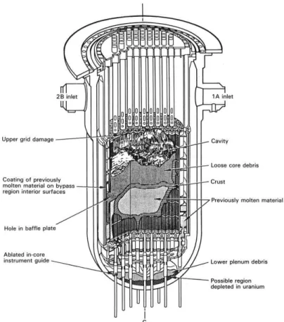
Figure 3: Final configuration of the TMI-2 reactor vessel and damaged core after the accident as reported by Broughton et al. [4]
Broughton et al. [4] estimated that about 45 % of the core mass was melted after the accident. It may be noted that from the protection of the public point of view, the safety systems worked very well. In fact, only a small fraction of the radioactive materials was released in the environment. In this case, the retention of the in-vessel corium mixture by the reactor vessel resulted efficient.
1.1.2 Fukushima Daiichi (2011)
A 9.0 magnitude earthquake with an epicentre in the ocean off the coast of Sanriku (Japan) occurred at 2:46 pm on March 11th, 2011. The control rods of all the operating units (units 1, 2 and 3 were operating whilst unit 4 was undergoing regular inspection) at the Daiichi NPP were automatically inserted and the reactors tripped. Due to the loss of electrical power, the emergency diesel generators automatically started and the reactors cooling begun. As a result of the tsunami that hit the Fukushima Daiichi NPP at 3:35 pm pumps and outdoor equipment for releasing the heat from the reactors to the sea were irreparably damaged and almost the entire nuclear installation was flooded. Furthermore, all the emergency diesel generators and the DC batteries were lost. In these conditions the residual heat of decay could not be removed from the reactor cores. The general outline of the accident evolution [5] is reported in Figure 4.
The sequence of events that led to the severe accident in unit 1 can be applied to unit 2 and 3. The timing at which the cooling systems were lost is however delayed from unit to unit. In the following a more detailed sequence of events will be given for unit 1 accident.
In unit 1, the water in the reactor vessel evaporated leaving part of the fuel bundles directly exposed to water vapour. Due to the elevated temperature of the fuel rods, the Zircaloy cladding reacted with the water vapour forming large amounts of hydrogen. The fuel itself
- 17 -
was damaged because of the high temperature reached at that time. The primary containment vessel was damaged as well. Hydrogen and radioactive materials leaked in the reactor building and gathered in its upper part. At 3:36 pm on 12th March the accumulated hydrogen ignited leading to an explosion. The gaseous and volatile fission products were thus released in the atmosphere. The reactor core experienced a meltdown forming a molten corium: it firstly accumulated at the bottom of the containment steel vessel, and then it pierced the vessel pouring on the underneath concrete. The so-called molten core/concrete interaction (MCCI) took place. The molten in-vessel corium start to ablate the concrete pit: the interaction at high temperature between in-vessel corium and the decomposition products of concrete led to the formation of a complex mixture called ex-vessel corium.
Figure 4: Outline of the accident evolution at Fukushima Daiichi units 1, 2 and 3 [5]. The reported sequence is simplified and considers only the main events that lead to the severe accident
1.1.3 Considerations on severe accidents - Defence in depth and EPR design
The Three Mile Island and the Chernobyl severe accidents stimulated the nuclear community and the nuclear security agencies reconsidering the approach for the design of new nuclear
- 18 -
reactors. The defence in depth philosophy is the result of a change in the nuclear installation design strategy. Defence in depth means preparing countermeasures corresponding to the various stages of an accident. In other words, if the first security action fails to stop the accident, a second action is put in place to prevent a further progression of the accident. The design of the European Pressurised Reactor (EPR, 1600 MWe) is based on the defence in
depth concept. The corresponding French security requirement is that there must be “no need for emergency evacuation outside the immediate vicinity of the plant, only limited sheltering, and no long-term restrictions in the consumption of food even in the case of a core melt accident” [6].
In the EPR concept, all the critical load situations in the reactor containment must be either “practically eliminated”, or avoided by specific design. In particular, these situations include:
- High pressure core melting - Hydrogen detonation - Steam explosion
- Penetration of the containment basement by the molten core. The schematic representation of the EPR design is reported in Figure 5.
Figure 5: EPR design [6]. IRWST=Internal Refueling Water Storage Tank
The core catcher is placed in a lateral spreading compartment, therefore a physical and functional separation exist between the core catcher and the concrete reactor pit. The reactor pit consists of a 0.5 m thick layer of sacrificial concrete backed up by a cylindrical shielding consisting of refractory
materials. This design allows a complete accumulation of the molten in-vessel corium before spreading.
1.2 PWR core degradation phenomena
As already seen in the previous sections, the loss of cooling of a PWR leads to core overheating due to the residual heat of decay. If this event is prolonged an accidental scenario occurs (Figure 6) [7].
- 19 -
Figure 6: Scheme of the main events occurring during a severe accident [7]
1.2.1 In-vessel corium retention
The description of the progression of a severe accident is paramount to be able to mitigate its consequences and possibly to terminate it. In this framework, the physicochemical behaviour of the reactor core materials under accident condition is capital. During the severe accident progression, the temperature inside the reactor may reach extreme values (2700-3200 K): this temperature rise leads to complex interactions between the fuel, the cladding, the control rods, etc. Hofmann [8] reported a straightforward representation of the in-vessel core degradation phenomena with increasing temperature (Figure 7).
Figure 7: Melting and chemical interaction temperatures leading to liquid phases formation during a severe accident in a LWR [8]
A crucial point is shown in this clear-cut scheme: the nuclear fuel (as a first approximation one may assume a UO2-fuel) can be already dissolved by molten Zircaloy at 1000 K below its
melting point. In fact, the uncontrolled temperature rise of the Zircaloy cladding due to oxidation by H2O leads first to the melting of the cladding and then to the dissolution of UO2
- 20 -
leading to the formation of a (U,Zr,O) melt: then the relocation of the fuel may take place already below 2273 K.
Since the end of the 70’s numerous studies have been performed on the chemical interaction between fuel and its cladding [9–13]. Several tests were performed between 1173 K and 1973 K. Hofmann and Politis [9] reported annealing test results showing the formation of different layers due to the direct UO2-Zircaloy interaction. Figure 8 shows a diffusion couple
profile obtained at 1673 K.
Figure 8: Sequence of layers obtained during diffusion couple test UO2-Zircaloy under oxidising
atmosphere (T=1673 K). It may be noted that a liquid phase is formed
During the UO2-Zircaloy interaction, a progressive reduction of the fuel was observed,
leading to the formation of oxidised form of zirconium, namely α-Zr(O) at the UO2-Zircaloy
interface and ZrO2 at the Zircaloy-oxidising atmosphere interface. The formation of these
phases leads to the embrittlement of the fuel cladding and to the loss of its mechanical stability. However, as long as the ZrO2 layer remains intact, the relocation of the molten
materials is prevented. If mitigation actions are not effective at this stage, the dissolution of ZrO2 and UO2 by molten Zircaloy may take place (M.S. Veshchunov, 1994) leading to the
loss of the first radiological barrier.
Starting from 1473 K the Inconel spacer grid and the control rods stainless steel (ss-316 18 wt% Ni, 8 wt% Cr) cladding melt due to chemical interactions. Direct contact with Zircaloy may drive liquefaction well below this temperature [14]. During the interaction with the control rods, the absorbers (silver, cadmium and indium) may further lower the liquefaction temperature resulting in an even lower UO2 dissolution temperature. In these
conditions, the relocation of a metallic and a ceramic melts, the in-vessel corium, in the lower-head of the reactor vessel happens as a direct consequence of these high temperature interactions. In the 3rd Generation LWR, the in-vessel retention is the chosen strategy: the reactor steel vessel is thus externally water-cooled to limit thermal creep.
Because of the existence of a miscibility gap in the liquid phase of the in-vessel corium system [15], inside the reactor a metallic and an oxidic melts stratify (Figure 9a). The density difference drives this phenomenon, leading the heavier oxidic melt to the bottom of the lower-head, and the metallic melt above the ceramic melt. Depending on the degree of oxidation of zirconium, the U/Zr ratio and on the amount of molten steel in the in-vessel corium, a heavy metal layer may relocate underneath the oxidic melt [15], as shown in Figure 9b.
- 21 -
a) b)
Figure 9: Possible in-vessel corium configuration in the case of an in-vessel relocation strategy. a) oxidic melt underneath the metallic melt; b) heavy metal melt formation under the oxidic pool [15] Since liquid metal has a low emissivity, the radiative heat transfer from the metal is limited. The main part of the heat release occurs at the molten metallic layer/steel vessel interface. If the thickness of the upper metallic layer is excessively reduced, the so-called focusing effect may take place. In this situation, the heat flux from the liquid metal to the steel vessel is important and it may lead to the vessel breach (if this heat flux is greater than the Critical Heat Flux, CHF=1.5 MWm-2 in the reported scenario). Seiler et al. considered the U-Zr-Fe-O system as a first approximation in-vessel corium. The authors showed that depending on the amount of dissolved iron an inversion of the melts density may be observed (Figure 10). The intersection between the oxidic phase density and the metallic phase density in Figure 10 gives the maximum amount of steel (iron simulates steel behaviour) that stratify under the oxidic pool. For example, for an in-vessel corium with 30 % of oxidised zirconium (C30 in Figure 10), the metallic phase is heavier than the oxidic phase until 25 tons of dissolved iron. This means that a considerable amount of steel may stratify under the oxidic pool. It may be also noted that the density of the oxidic phase is practically not affected by the iron addition suggesting that the solubility of iron in the oxidic phase is limited.
Figure 10: Evolution of the density of oxidic (red line) and metallic (black lines with different amount of initial oxidised zirconium) melts as a function of the amount of dissolved iron [15]
These calculations were performed by coupling thermochemical data with thermal and thermo-hydraulics data. The uncertainties related to the chemical composition of the
- 22 -
maximum mass of steel that can stratify underneath the oxidic pool. The coupling with
thermo-hydraulics allowed to determine the minimum amount of steel needed to maintain the heat flux under the CHF (in the reported scenario the calculated minimum mass of steel is 80 tons). A better thermodynamic description of the in-vessel corium system is thus needed in order to improve the simulation accuracy.
Once the second radiological barrier is lost, the relocated molten material can interact with the vessel containment structures: the ex-vessel stage of the severe accident starts. During the Three Mile Island accident the in-vessel retention worked, preventing the direct interaction between the molten corium and the concrete. On the other hand, during the Fukushima Daiichi accident the reactor vessel failed, leading the molten corium contacts the concrete.
1.2.2 Ex-vessel corium retention
The ex-vessel relocation of the molten core material is the last retention option for 2nd and 3rd Generation nuclear reactor before a significant release of radioactive materials in the environment. In the case of the EPR configuration, the in-vessel retention is only temporary. It was chosen instead ex-vessel retention in a dedicated lateral core catcher [6].
When the molten core pours on the containment concrete the so-called Molten Corium-Concrete Interaction (MCCI) will start. The molten corium at about 2673 K starts interacting with the concrete. At the beginning, the MCCI is controlled by the melt overheat that heats the concrete. CO2 and steam are released and concrete starts to melt. The released gases may
then move within the corium oxidising zirconium and steel. Afterwards the decay heat becomes the main source of heat. If the ex-vessel retention actions work, the radioactive materials stay inside the reactor containment, preventing a massive release in the environment. From the chemical point of view, all the components of the concrete (mainly CaO, SiO2, Al2O3, MgO, H2O, CO2) are added to the already complex in-vessel system. The
ex-vessel corium may then be defined as a metallic/oxidic mixture within the in-vessel corium+concrete system. As a first approximation the U-Zr-Fe-Ca-Si-O system can be considered as a representative ex-vessel corium.
High temperature concrete decomposition, gas bubbles agitation, formation of several phases, oxidation of metals, ablation process are only a part of the phenomena observed during MCCI. The whole comprehension of MCCI depends on a multitude of parameters: the design of the reactor containment and the mitigation actions applied during the severe accident may reduce the effect of an ex-vessel relocation of the molten core. In the same way, the knowledge of the physicochemical properties of in-vessel corium, concrete and ex-vessel corium can help the reactor designers to use the appropriate materials during the project realisation. In fact, thermodynamic and thermochemical data are fundamental for severe
accident codes as TOLBIAC-ICB [16], ASTEC [17], MAAP [18] and MELCOR [19]. The
coupling of thermodynamics with thermo-hydraulics based software, allows describing the thermo-physical properties of molten corium both during in-vessel and ex-vessel retention. The presence of a miscibility gap in the liquid phase of the corium system plays a crucial role for the simulation of the accidental scenario: thermo-hydraulics has to face two liquids (in addition to water) with different density and viscosity. Furthermore, the residual heat of decay that drives the accident progression is not homogeneously distributed within the oxide and the metallic liquids. The oxide liquid has a larger solubility for the fission products and the radioactive actinides. This fact has to be taken into account during a severe accident simulation and during the design of the reactor.
- 23 -
1.3 Concluding remarks
The comprehension of the phenomena occurring during a severe accident is paramount for the design of new reactors and to find more efficient mitigation actions. Since the beginning of the civil nuclear industry, several experimental programs have been performed to investigate all these phenomena. The physicochemical properties of the in-vessel materials were studied as well as the complex phenomena involved during MCCI.
The main objective of this thesis is contributing to the thermodynamic description of the physicochemical interactions occurring during a severe accident. As already introduced, the real corium system is extremely complex and difficult to describe because it includes a large number of chemical elements. In this framework a simplified version of the in-vessel and ex-vessel systems are considered. Since in some cases the UO2-based fuel can be replaced by a
(Pu,U)O2-based fuel, the so-called MOx, the U-Pu-Zr-Fe-O system will be considered as the
prototypic in-vessel corium, neglecting as a first approximation fission products and additional elements contained in the metallic structures inside the vessel (e.g., nickel, chromium, niobium …). Notwithstanding the high item importance of this system for the severe accident comprehension, a lack of data exists on its high temperature behaviour. In particular, the experimental needs on the sub-systems are:
- O-U-Zr: extension of the miscibility gap in the liquid phase and liquidus transition in the Zr-rich side of the ternary phase diagram
- O-Fe-Zr: lack of experimental data within the ternary phase diagram - O-Fe-U: lack of experimental data within the ternary phase diagram
- Pu-containing systems: lack of experimental data mainly due to difficulties related to the handling Pu-containing samples
In this framework, during the present study new experimental results on the O-U-Zr, Fe-Zr-O, Pu-Zr-Fe-Zr-O, U-Zr-Fe-O and U-Pu-Zr-O systems were obtained. Those results have been used for the thermodynamic reassessment of the in-vessel corium prototype system using the CALPHAD method [20,21].
For the ex-vessel corium description, the concrete will be considered as an oxide mixture (without taking into account H2O and CO2 since these compounds have already been released
due to high temperatures): the prototypic concrete will be simulated by the Al2O3-CaO-SiO2
system. Therefore, the final prototypic ex-vessel corium will be the U-Pu-Zr-Fe-Al-Ca-Si-O system.
In the second chapter, the critical review on the existing literature on prototypic in-vessel corium sub-systems is reported. The selection of significant experimental allows the re-assessment of the thermodynamic model of the in-vessel corium system. Furthermore, a selection of large scale experiment results will be given.
The third chapter reports the experimental investigation on interesting in-vessel corium sub-systems. This new set of data will be used for the thermodynamic modelling as well. The fourth chapter contains the thermodynamic modelling on the prototypic in-vessel corium. The reassessed model will be discussed in detail. The last part of the fourth chapter is dedicated to solidification path calculations to better interpret the current experimental results.
Chapter five represents an exploring approach to investigate two complex prototypic ex-vessel corium samples. Solidification path calculations will be used to test the validity of the current model coupled with the TAF-ID database.
In Chapter six, the novel experimental setup – ATTILHA – will be presented. The first results on well-known system as well as the future perspectives for this device will be discussed.
- 24 -
The general conclusions of this thesis, the impact of the present work and the perspectives for future investigations will be finally presented in the last Chapter.
- 25 -
1.4 References
[1] Electricity Information. Paris: OECD/IEA, 2014.
[2] INES The International Nuclear and Radiological Event Scale User’s Manual. Vienna:
OECD/NEA IAEA, 2008.
[3] J. R. Lamarsh and A. J. Baratta, Book, Introduction to Nuclear Energy. 2012.
[4] J. M. Broughton, P. Kuan, D. A. Petti, and E. L. Tolman, “A SCENARIO OF THE THREE MILE ISLAND UNIT β ACCIDENT,” Nucl. Saf., vol. 87, pp. 34–53, 1989.
[5] “The Development of and Lessons from the Fukushima Daiichi Nuclear Accident,” TEPCO report 2013.
[6] M. Fischer, “The severe accident mitigation concept and the design measures for core melt retention of the European Pressurized Reactor (EPR),” Nucl. Eng. Des., vol. 230, pp. 169–180, 2004.
[7] C. Journeau, “Contribution des Essais en Matériaux Prototypiques sur la Plate-Forme PLINIUS à l’Etude des Accidents Graves de Réacteurs Nucléaires,” HDR Thesis, 2008.
[8] P. Hofmann, “Current knowledge on core degradation phenomena, a review,” J. Nucl. Mater., vol. 270, no. 1-2, pp. 194-211, 1999.
[9] P. Hofmann and C. Politis, “The kinetics of the uranium dioxide—Zircaloy reactions at high temperatures,” J. Nucl. Mater., vol. 83, no. 2-3, pp. 375-397, 1979.
[10] D. R. Olander, “The UO2-Zircaloy chemical interaction,” J. Nucl. Mater., vol. 115, pp. 271–
285, 1983.
[11] P. Hofmann and D. Kerwin-Peck, “UO2/Zircaloy-4 chemical interactions from 1000 to 1700°C
under isothermal and transient temperature conditions,” J. Nucl. Mater., vol. 124, pp. 80-105, 1984.
[12] W. Dienst and P. Hofmann, “Chemical Interations between UO2 and Zircaloy-4 from 1000 to
2000 oC,” Nucl. Technol., vol. 65, pp. 109–124, 1984.
[13] P. Nikolopoulos, P. Hofmann, and D. Kerwin-Peck, “Determination of the interfacial energy and work of adhesion in the UO2/Zircaloy-4 diffusion couple,” J. Nucl. Mater., vol. 124, pp.
106–113, 1984.
[14] P. Hofmann, S. Hagen, V. Noack, G. Schanz, and L. Sepold, “Chemical-physical behavior of light water reactor core components tested under severe accident conditions in the CORA facility,” Nucl. Technol., vol. 118, pp. 200–224, 1997.
[15] J. M. Seiler, B. Tourniaire, F. Defoort, and K. Froment, “Consequences of material effects on in-vessel retention,” Nucl. Eng. Des., vol. 237, pp. 1752–1758, 2007.
- 26 -
[16] B. Spindler, B. Tourniaire, and J. M. Seiler, “Simulation of MCCI with TOLBIAC-ICB code based on the phase segregation model,” Nucl. Eng. Des., vol. 236, pp. 2264–2270, 2006. [17] J. P. Van Dorsselaere, C. Seropian, P. Chatelard, F. Jacq, J. Fleurot, P. Giordano, N. Reinke, B.
Schwinges, H. J. Allelein, and W. Luther, “THE ASTEC INTEGRAL CODE FOR SEVERE ACCIDENT SIMULATION.”
[18] “Modular Accident Analysis Program User’s Manual,” 1λλ4. [19] “MELTCOR Computer Code Manuals,” 1λλ5.
[20] N. Saunders and A. Miodokwin, Book, CALPHAD - Calculation of Phase Diagrams, A
Comprehensive Guide. 1998.
[21] H. Lukas, S. Fries, and B. Sundman, Book, Computational Thermodynamics - The Calphad
- 27 -
Chapter 2
– Critical review of literature data
During the last six decades numerous research groups investigated the high temperature behaviour of the chemical systems involved during a severe accident in a PWR. Above 1300 K the interaction between the UO2-based nuclear fuel and the Zircaloy cladding may
lead to the formation of a liquid phase and to the loss of the first radioactive barrier. In this framework, the ternary O-U-Zr system has been studied with particular interest. The molten O-U-Zr mixture may then interact with the metallic structures inside the reactor (stainless steel coming from the control rods cladding and Inconel spacer grids) and finally with the reactor steel vessel, leading to the formation of the so-called in-vessel corium. As a first approximation the U-Zr-Fe-O system may be considered as the simulant for the in-vessel corium behaviour. In order to deduce the thermodynamic properties of the U-Zr-Fe-O system, the three ternary subsystems may be considered. In this framework, the U-Fe-O and Zr-Fe-O systems are of significant interest. Plutonium may be added to the in-vessel corium composition if MOx fuels are considered leading to the more complex U-Pu-Zr-Fe-O system. In the following a critical review of the thermodynamic and phase diagram data for the ternary O-U-Zr, U-Fe-O, O-Fe-Zr systems, and the quaternary U-Zr-Fe-O and U-Pu-Zr-O systems will be given. The data will be chronologically listed. This review allowed the
selection of the experimental data that have been used during the reassessment of the
thermodynamic model of the simplified in-vessel corium system (U-Pu-Zr-Fe-O).
In the case of reactor vessel mechanical failure, the molten in-vessel corium directly contacts the concrete of the reactor containment leading to the formation of the complex ex-vessel corium system. The composition of the concrete used for the reactor containment is not a constant parameter; ideally for each nuclear power plant one should refer to the specific concrete composition. In order to simplify and generalise the study, the water and CO2
contributions are neglected (at the severe accident temperature one may consider that water and CO2 are not present anymore in the ex-vessel corium mixture). Considering only the main
constituent of the concrete, the Al2O3-CaO-SiO2 can be taken as the representative system. In
the present work, the will not be further investigated, considering satisfactory the thermodynamic model described in the TAF-ID thermodynamic database [1].
The second part of the chapter is dedicated to the accidental scenario phenomenology. The main phenomena occurring during the first in-vessel retention and then during the Molten Corium – Concrete Interaction (MCCI) are described and a selection of large scale experiments will be given. It might be noted that a limited number of data are available on the thermochemistry of the MCCI.
2.1 Thermodynamic and phase diagram data on in-vessel corium systems
In this section the existing literature on the systems investigated during this work will be presented. The thermodynamic and phase diagram data of the ternary O-U-Zr, U-Fe-O, O-Fe-Zr and Pu-O-Fe-Zr-O systems as well as of quaternary U-O-Fe-Zr-Fe-O and Pu-U-O-Fe-Zr-O systems are reported.2.1.1 O-U-Zr system
Saller et al. performed the first investigation of the phase stability relations in the O-U-Zr system in 1955 [2]. The authors investigated 20 samples on the UO2-Zr section by heat
- 28 -
treatments and proposed three tentative sections at 810 K, 977 K and 1373 K. Juenke & White (1970) [3] investigated the interaction between UO2 based fuel and the Zircaloy cladding. The
UO2-Zr pseudo-binary system was studied above 1900 K. A thermal arrest technique was
used to explore the UO2 rich region of the phase diagram, whilst annealing and quench tests
were performed to identify the phases present at equilibrium at a given temperature. The heating method was not specified.
In the UO2 rich region the authors expected to find liquidus and solidus lines because of the
similarities with the U-UO2 monotectic system. The samples were prepared placing metallic
Zr in UO2 crucibles, weighing about 34 g, and sealed under vacuum in tungsten crucibles.
For the quench tests the samples were firstly heated for 1.5 hours in the temperature range 1920 K – 2700 K and then quenched and analysed using metallography and X-ray diffraction. With the obtained experimental points they established the high temperature region of the UO2-rich zone (see Figure 1).
Figure 1: Tentative Zr-UO2 phase diagram reported by Juenke & White [3]
Figure 1 shows the experimental results obtained by Juenke & White. Above 2673 K, the authors found a miscibility gap in the liquid phase: a metallic liquid L1 and an oxide liquid L2 were observed. The composition of the two liquids in equilibrium was not reported. The authors proposed a tentative phase diagram based on their results. The existence of a monotectic reaction at about 2673 K was argued on the basis of the similarities between the Zr-UO2 system and the U-UO2 system. However, from a thermodynamic point of view, the
Zr-UO2 system given in Figure 1 cannot be treated as a pseudo-binary system as it was
interpreted by Juenke & White. This is due to the fact that this system contains a ternary monotectic reaction and thus the tie-lines correspond to the three-phase equilibrium [L1+L2+(U,Zr)O2-x] from a triangle in the ternary O-U-Zr system. In fact, the degree of
freedom ( ) of this ternary monotectic reaction is equal to 1. Using the Gibbs’ phase rule [4] the degree of freedom of a system, i.e., the number of independent variables necessary to fully define the state of the system, is given by:
C1
where C is the number of components (C=3 in a ternary system), ϕ the number of phase in equilibrium (ϕ=3 for a monotectic reaction). Considering the pressure as a fixed intensive variable, in the present case one obtains:
- 29 - 1 3 1 3 .
Therefore, the temperature can vary across a ternary monotectic reaction. The experimental data obtained by Juenke & White can be considered reliable but are lacking of experimental details. The reported results are selected for the thermodynamic modelling.
Politis (1976) [5] investigated the UO2-ZrO2-U-Zr sub-system of the O-U-Zr system. The
author performed heat treatments at 1273 K, 1773 K and 2273 K and metallographic analyses. He also studied the ZrO0.51-UO2 section by optical pyrometry. The author confirmed the
presence of a miscibility gap in the liquid phase within the O-U-Zr ternary system above 2673 K (Figure 2b). The temperature of the eutectic reaction [ZrO0.51+(U,Zr)O2-x] L was
measured equal to 2073±20 K at 5 mol% UO2. An inconsistency exists between the reported
ternary isothermal section at 2273 K and the ZrO0.51-UO2 section (see Figures 2a and 2b): the
liquidus line in the ternary section crosses the ZrO0.51-UO2 section at 14 mol% UO2 whilst in
the isopleth it is reported a value of 8 mol% UO2. Furthermore, Politis did not reported the
domain of existence of α-Zr(O) in the isothermal ternary diagram at 2273 K.
Note also that agreementing to Politis, the liquidus line in the isothermal ternary section at 2273 K crosses the Zr-UO2 section at about 55 mol% UO2 whilst in the Zr-UO2 isopleth
section given by Juenke & White, the UO2-content of the liquidus line at the same
temperature is situated at 15 mol% UO2.
Skokan (1984) [6] investigated the inconsistency of Politis’ work concerning the position of the liquidus line as well as the eutectic temperature. The author performed high temperature thermal analysis (DTA) and pyrometric measurement to investigate the liquidus curves between 1773 K and 2273 K. The samples were prepared starting from a mixture of UO2,
ZrO2 and Zr powders. The post-experiment analyses were performed by means of X-ray
diffraction and metallography.
First the author fixed the value of the oxygen concentration of α-Zr(O) at 30 at% ~ ZrO0.43
(Politis reported 34 at% O ~ ZrO0.51).
a) b)
Figure 2: Results reported by Politis [5]. a) ZrO0.51-UO2 section. b) Isothermal ternary section at 2273
K. ● = liquid; ○ = solid; solid+liquid
The measured eutectic temperature (2173 K) is 60 K higher than previous works [5]. The eutectic composition in the α-Zr(O)-UO2 section lies at 15 mol% UO2.
- 30 -
The maximum solubility of UO2 across the α-Zr(O)-UO2 section at 2273 K is 16 mol% UO2,
in agreement with Juenke & White. This value corroborates the results on the isothermal section reported by Politis, confirming the error in the isopleth section. Politis [5] and Skokan [6] reported an isothermal monotectic reaction lying in the ZrO0.51-UO2 section. As already
pointed out for Juenke & White’s work [3], the use of the term isothermal monotectic passing through a ternary system is not thermodynamically correct.
Yamanaka et al. investigated the isothermal section at 1773 K by heat treatment. The samples were then analysed by X-ray diffraction, metallography examination and scanning electron microscopy.
In a series of publications, Hayward & George (1994-1996) [7–10] studied the interaction between UO2 and Zircaloy from 2273 K to 2773 K. In particular they focused their interest on
the study of the solubility of unirradiated UO2 in initially O-free Zircaloy and in Zircaloy with
an initial 25 at% O content. A powder of Zircaloy was firstly placed inside a UO2 crucible.
Thus, the whole system underwent the scheduled heat treatment.The authors pointed out that the solubility of UO2 in the liquid phase increases with temperature and decreases with the
initial amount of oxygen in the Zircaloy cladding. Furthermore they observed the progressive shrinking of the two phase [(U,Zr)O2+L] region in the ternary O-U-Zr system as soon as the
temperature raises.
It may be noted in Figure 3 that the authors did not find any miscibility gap in the liquid
state in disagreement with Politis [5] and Juenke & White [3].
Figure 3: ZrO0.54-UO2 section reported by Hayward and George [9]
Note however that the isopleth section investigated by the authors is at the limit of the domain of existence of the miscibility gap: a slight change in the sample composition during the experiment (e.g., due to the vaporisation of UO that shifts the global composition of the sample towards the Zr-O side of the ternary diagram) could easily lead to a composition outside the immiscibility region. None of the experimental results of Hayward & George
will be considered for the thermodynamic modelling.
One of the main objectives of the PhD thesis of Maurizi (1998) [11] was the determination of the liquidus line within the O-U-Zr system at 2273 K. For a ratio U/Zr=1.35, the author obtained an oxygen solubility in the ternary (U,Zr,O) liquid of 7±1 at% O, as reported in Figure 4.
- 31 -
Figure 4: O-U-Zr isothermal section calculated at 2273 K [11]
The experimental result obtained at 2273 K allowed reassessing the liquidus line shape: the resulting oxygen solubility in the liquid phase is lower compared with the previous works of Politis [5] and Skokan [6]. The solubility data obtained by Maurizi is retained for the
thermodynamic reassessment.
In the same period Guéneau et al. (1998) [12] obtained new experimental data on the miscibility gap in the liquid phase in the ternary O-U-Zr and in the binary U-UO2 system.
Recalling what previously showed by Juenke & White [3] and Politis [5], a wide miscibility gap in the liquid state exists in the ternary O-U-Zr system.
The authors used an electron bombardment system in order to melt and quench different samples. In particular, for the investigation of the O-U-Zr system they used two ternary alloys:
- (UO2+Zr) mixture
- (U+ZrO2) mixture
Concerning the binary U-UO2 system, the investigations were conducted by placing a UO2
pellet under an ingot of pure natural uranium. The post-melting analysis of the U-UO2 sample
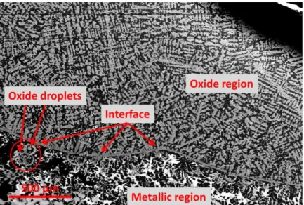
showed a microstructure typical of two immiscible liquids. In Figure 5 the authors identified quenched droplets of oxide liquid L2 within a solidified U-rich metallic liquid L1.
Figure 5: Back scattered electrons image showing the microstructure of the U-UO2 quenched sample
from T=3100 K. It may be noted the presence of quenched droplets of liquid L2 (oxidic) within the solidified liquid L1 (metallic) [12]
The post-melting analyses performed on the quenched U-ZrO2 sample also revealed the
- 32 -
Figure 6 reports a BSE image of the quenched U-ZrO2 sample. A droplet of solidified oxide
liquid is surrounded by quenched metallic liquid.
Figure 6: Backscattering electrons image of the U-ZrO2 sample after quenching [12]
The authors employed their experimental results and other significant literature data [3] to redefine the thermodynamic description of the ternary O-U-Zr system. The interaction parameters are not reported in the paper. It may be pointed out that Guéneau et al. are the only authors reporting a tie-line for the miscibility gap in the ternary liquid phase. Even if affected by a significant uncertainty due to the high temperature reached during the experiment and the control of the cooling rate, this result is paramount because it allows a better shape of the immiscible region. For this reason these tie-line data will be used for the thermodynamic
assessment of the O-U-Zr system.
Bakardjieva et al. (2008) [13] summarised the experimental and modelling results obtained on the system corium/concrete. Of particular interest are the results on the pseudo-binary Zr-UO2
system. Using the laser heating technique [14], specimens in the UO2-rich region were
studied. The specimens were prepared pressing into pellets and sintering under inert atmosphere at 1973 K a mixture of UO2 and ZrO2 (or Zr) powders. The results confirm the
presence of a miscibility gap in the liquid phase in the Zr-UO2 section. Furthermore, the
liquidus/solidus results obtained for the same section were in good agreement with the results of Juenke & White [3].
In the framework of the CORPHAD project (Phase Diagrams for Multicomponent Systems Containing Corium and Products of its Interaction with NPP Materials), the aim of which is the study of the major binary, ternary and quaternary systems involved during a severe accident, some experimental results were obtained on the O-U-Zr system. In the MASCA (MAterial SCAling) project tests [15], two immiscible liquids (one oxidic the other metallic) were observed studying the O-U-Zr system. The experimental results compared with calculation performed with GEMINI-2 software and NUCLEA database are shown in Table 1. It can be noted from Table 1 that a significant discrepancy exists between experimental data and calculations results on the oxygen and zirconium contents in the metallic liquid. The experimental miscibility gap appears to be significantly smaller than the calculated one. The calculations are based on the results of Guéneau et al. [12].
- 33 -
Table 1: Comparison between experimental data and calculations (GEMINI2 + NUCLEA database) of coexisting liquids in the O-U-Zr ternary system [15]
These measured tie-lines compositions will not be used for the thermodynamic modelling; the authors argued that segregation phenomena occurred during the experiment,
leading to the shift of the tie lines. A more detailed discussion on these experimental results will be given in Chapter 3.
Table 2 reports the O-U-Zr phase diagram data selected for the thermodynamic modelling. These data are used to reassess the ternary interaction parameters of the O-U-Zr system.
Authors Type of data T (K) Comments
Juenke & White [3] Phases equilibria
Liquidus/solidus across the Zr-UO2 section
2073-2673 K
2673-3140 K UO2 side
Politis [5] Phases equilibria 2000-3100 K
Maurizi [11] Solubility of oxygen in ternary (U,Zr,O)
liquid 2273 K U/Zr=1.35
Guéneau et al. [12] Miscibility gap tie-line 3223 K Table 2: Phase diagram data retained for the thermodynamic modelling
It must be pointed out that most of the experimental data obtained within the O-U-Zr system concern the region close to the Zr-UO2 section between 2000 and 2600 K due to the interest
of the Zircaloy cladding-UO2 fuel interaction during a severe accident. However, in order to
have a straightforward description of the O-U-Zr thermodynamics, new experimental data
are needed, especially to better describe the shape of the miscibility gap in the liquid phase and the liquidus line in the oxygen-poor side of the ternary phase diagram.
2.1.2 UO2-ZrO2 system
During the normal functioning of a PWR, inside the vessel, an oxidising environment is present. In the case of a severe accident it is thus frequently imposed that the corium pouring on the concrete underneath the damaged steel vessel should be completely oxidised. In this framework, the pseudo-binary UO2-ZrO2 system at high temperature is paramount. Several
studies were performed on this system since the 1950's, showing rather important experimental constraints related to the control of the oxygen level during the tests.
Lambertson & Müller (1953) [16] heat-treated and quenched UO2-ZrO2 samples to determine
the post-melting compositions by chemical analysis and XRD. The samples were firstly sintered at 1973 K under pure H2. The experimental temperature was controlled by using
thermocouples and optical pyrometers. The authors investigated the liquidus/solidus transitions. They reported a minimum in the liquidus/solidus lines at 2823 K at a composition of about 52.5 mol% ZrO2. Since the reported liquidus temperatures are close to 2900 K, it can
be concluded that the chemical homogenisation of the samples is achieved. The liquidus data
![Figure 6: Scheme of the main events occurring during a severe accident [7]](https://thumb-eu.123doks.com/thumbv2/123doknet/12701310.355653/20.892.256.640.84.353/figure-scheme-main-events-occurring-severe-accident.webp)
![Figure 2: Results reported by Politis [5]. a) ZrO 0.51 -UO 2 section. b) Isothermal ternary section at 2273 K](https://thumb-eu.123doks.com/thumbv2/123doknet/12701310.355653/30.892.107.778.719.1046/figure-results-reported-politis-section-isothermal-ternary-section.webp)
![Figure 7: Tentative UO 2 -ZrO 2 phase diagram reported by Cohen & Shaner [18]. The liquidus and solidus data are taken from [19], whilst the black and white triangles from [17]](https://thumb-eu.123doks.com/thumbv2/123doknet/12701310.355653/36.892.303.577.77.457/figure-tentative-diagram-reported-shaner-liquidus-solidus-triangles.webp)
![Figure 14: Tentative phase diagram of the ZrO 2 -FeO system obtained in [37]](https://thumb-eu.123doks.com/thumbv2/123doknet/12701310.355653/41.892.251.644.766.1017/figure-tentative-phase-diagram-zro-feo-obtained.webp)
![Figure 16: Tentative phase diagrams reported by Mardon et al. [39]. a) PuO 2 -ZrO 2 section;](https://thumb-eu.123doks.com/thumbv2/123doknet/12701310.355653/43.892.114.789.73.342/figure-tentative-phase-diagrams-reported-mardon-puo-section.webp)
![Figure 17: Phases in equilibrium at 2773 K in function of the oxygen and iron content [43]](https://thumb-eu.123doks.com/thumbv2/123doknet/12701310.355653/44.892.259.636.98.404/figure-phases-equilibrium-k-function-oxygen-iron-content.webp)
![Figure 22: Concrete test section used during the MCCI VBS-U1 test [57]](https://thumb-eu.123doks.com/thumbv2/123doknet/12701310.355653/53.892.170.712.82.406/figure-concrete-test-section-used-mcci-vbs-test.webp)