Analyzing Mechanical and Software Solutions in their Patents
by
Nicolas R. Villarruel
SUBMITTED TO THE DEPARTMENT OF MECHANICAL ENGINEERING IN PARTIAL FULFILLMENT OF THE REQUIREMENTS FOR THE DEGREE OF
BACHELOR OF SCIENCE AT THE
MASSACHUSETTS INSTITUTE OF TECHNOLOGY
JUNE 2006
©2006 Nicolas R. Villarruel. All rights reserved The author hereby grants to MIT permission to reproduce
and to distribute publicly paper and electronic copies of this thesis document in whole or in part
in any medium now known or hereafter created.
'
r
ARCHIVESSignature of Author:
Certified by:
Accepted by:
-
I/ a-
j
Detent
of
}h
cal Engineering
7/7/ May 12, 2006I 1. c
/; ' "
(Daniel
D.
Frey
Assistant Professor of Mechanical Engineering Assistant Professor of Engineering Systems
Thesis Supervisor
John H. Lienhard V Professor of Mechanical Engineering Chairman, Undergraduate Thesis Committee
MASSACHUSETTS INSITUTE
OF TECHNOLOGY
AUG 0 2 2006RIES
LIBRARIES
Analyzing Mechanical and Software Solutions in their Patents
by
Nicolas R. Villarruel
Submitted to the Department of Mechanical Engineering on May 12, 2006 in partial fulfillment of the requirements for the Degree of Bachelor of Science
ABSTRACT
An analysis of patents was conducted in order to find the motivation and reasons behind selecting either a mechanical or software solution. The reasons for selecting a
mechanical solution were claimed to be for simplicity, reliability, and robustness while the reasons for selecting a software solution were for increased performance and
flexibility. The three cases evaluated were fuel regulation, power and torque distribution, and engine valve timing. A tendency to use mechanical solutions to provide a simpler and more reliable device was found while software solutions were used when greater performance was desired.
Thesis Supervisor: Daniel D. Frey
Introduction
Success in an operational system is dependent on the devices in that system operating properly. For a device to operate properly it must be able to perform the specified operation reliably and still maintain the level of performance which meets the standard set by the developer. When a developer chooses to make improvements to a system or device, the operation must still perform reliably, maintain a new level of performance or a combination of both. For some systems where both mechanical and software based devices can be applied, a decision is made to determine which solution will better the overall operation. The purpose of this paper is to observe and analyze some of the proposed solutions to given performance areas. A trend will be seen which shows a tendency to select a more mechanical solution when reliability and simplicity is required, and software or electronic solutions when increased performance, greater flexibility and a wider range of operation are desired.
A system or device is reliable when it is able to perform the operation it was designed when it is needed. The device must be able to operate under a variety of
conditions to certain extremes and avoid mistakes in performance.' The system must also be robust or able to not only avoid mistakes but also to not fail in the variety of
conditions the device will operate in.2 Robustness can be achieved though simplicity and
fewer possible points where the device itself could fail. These are the traits which a developer pursues in an invention or idea when a reliable design is desired. A system increases in performance and flexibility when it is able to perform a wider range of operations than previously. The system is no longer confined to a limiting range of operations, and is also able to perform the appropriate operation for the conditions or environment. With the greater flexibility, the device is able to optimize performance to a greater standard, operate in a greater range of conditions, and have more varied and exact control.
A purely mechanical solution for this paper is defined as a device or invention which is comprised of only mechanical elements and does not have any electronic or software controlled components. The operation of the device is not dependent on an
1 Clausing and Frey. pg. 245. 2 Clausing and Frey. pg. 246.
electronic signal or software controller such as a microprocessor, but instead relies on mechanical signals or input and control to conduct the specified operation. In the selected patents, only a few of the inventions are purely mechanical. Many are
mechanical devices integrated with software controlled technology. The importance in analyzing these mixed devices will be to isolate the mechanical and software components and observe the motivations behind each separately. While the entire device may be an integration of mechanical and software or electronic components, the patents will still prove for the purposes of this paper.
Software solutions are those that apply a controller to the overall operation and ultimately run the device. These controllers usually have sensors to detect the conditions of the device as it operates, and the ability to send signals to control components of the device, such as electric motors or actuators. A software solution requires control which is not mechanical in nature, but rather relies on a program, simple or complex, to decide when or how the device will operate. Unless these components are imbedded in a purely electrical device, such as a computer, they operate mechanical components. In the patents selected, the software components do operate mechanical devices and will be observed individually.
The analysis of patent literature cannot be the only method to determine the motivation and purpose behind either a mechanical or software device. A patent does not even have to be physically built in order to be approved, which eliminates the ability to observe how the device actually operates in real world conditions. The purposed of this paper is not to be a comprehensive study of the reasoning behind the design of these improvements, but a part which can provide insight to some of the original intentions of an invention. The patents are limited in what they state because many of the mistakes which will arise are only apparent after their sustained use. The goal of this paper is to observe the intended improvements and motivations of the developer as they relate to mechanical and software solutions.
In order to prove these arguments, a review of patent literature will be made to evaluate solutions created by different developers. Comparisons will be made between the mechanical and software based solutions to a specific performance problem. The objective is to find the trends which exist between the mechanical and software based solutions for performance improvement over a series of requirements. A review will be made of the patents for the problem in the system, the proposed solution to the problem, the motivation to choose the specified solution, and the intended improvements the solution will make to the system.
The proposed solution and intended improvements are vital in analyzing the desired outcome of an invention, whether or not it is actually produced. Here the main objective of the invention is described, with the description of the design explaining how the solution will achieve the stated claims. The driving motivation for pursuing the invention will also be important to analyze, it is usually stated in the background or summary of the invention within patent the. Here the developer states the past history of the problem being tackled including previous inventions and solutions. The developer then uses the shortcomings of the previous solutions to develop the claims for the patent.
The three cases which will be evaluated are fuel control and regulation, driving force and torque distribution, and valve timing for an internal combustion engine. Each of these cases has both purely mechanical solutions and software or electronic controlled solutions which seek to improve the operation in some manner. A number of patents for each case will be evaluated to observe the intended solutions and motivations for the performance problem. Not all of the patents are purely mechanical or software based solutions, but the reasons for selecting either type of solution will be given.
Fuel control and regulation
Fuel control and regulation in engines are paramount in determining the speed, power, and torque an engine will put out at a given time. This case will look at a few proposed mechanisms to help govern and regulate the fuel input to an engine. By evaluating the patents of these mechanisms, certain motivations and intended
improvements can be revealed and analyzed. These motivations can then provide insight to the trends stated earlier.
Four patents for mechanisms which intend to improve fuel regulation were selected to review the proposed solutions. One of the mechanisms, proposed by Boeing, claimed a purely mechanical solution to fuel governing. Two of the other mechanisms claimed they would improve fuel governing by having a selection of predetermined parameters. However there are differences between the two, and the approaches and motivation are interesting to note. The final mechanism proposed by Nissan is an electronic-hydraulic governor which relies on an electrical control system to send the regulation signals for fuel control. All of these proposed solutions intend to improve fuel regulation, but the approaches and mechanisms are all quite different.
The first governor, United States Patent 5,234,014, was submitted in 1993 by the Boeing Company for use in its turbine engines. In the patent's abstract, the device is described as follows: "a mechanical fuel control governor employs a flyweight assembly for lifting the spindle of a fuel valve and allowing fuel to be bypassed from a high pressure line."3 When the assembly is spun to a certain speed, the spindle is lifted due to centrifugal force and changes to flow of the fuel to the engine. The main improvement this patent is claiming is a valve spindle, the one which rises to change the fuel flow, which rotates at a velocity fractional in proportion to the ball head speed. This reduction in spindle speed without affecting the overall assembly speed allows for minimal leakage
of the fuel valve.4
The governor design is similar to the old governor placed on the Watt steam engine. The classic design of that governor was two ball weights which when revolved at increasing velocity, rose up due to centrifugal force. When they reached a certain height, they disengaged the throttle valve of the engine and regulated the speed to a specified limit. The following image is a drawing of this classic mechanism.
3 Abstract. Patent 5,234,014. 4 Abstract. Patent 5,234,014.
ii
Figure 1: Flyball Governor Mechanism
The mechanism was purely mechanical and simple in its design. It has limited degrees of freedom to only rotate which will slowly disengage the throttle. The limitation of this design is that only one setting can be used to determine when the throttle will be disengaged. The governing of the throttle is also completely dependent on the angular velocity and no other parameters of the engine system. The design is still robust and reliable as long as the components used to construct the device are of good quality.
The fuel control governor proposed by Boeing uses the same mechanism of flyweights moving outboard due to a centrifugal force. The device has two weights attached to the revolving spindle which are free to move out in the radial direction. One of the main differences is once the spindle is lifted the throttle is not entirely disengaged, but the fuel flow is altered. Also important to note is the adjustment screw on top of the mechanism allowing for some flexibility in the design, which was not as easy to
configure in the classic flyball design. The figure from patent document gives a cross-sectional view of the proposed governor.
tA in a £ a u7. P
Figure 2: FIG.1, Patent 5,234,014. Vertical Cross Sectional View
The weights (60) are attached to the spindle which directly controls the fuel flow into the engine being governed. The horizontal cross section allows viewing of the position of the weights in relation to the spindle.
8 'U I_-iA U I
-T'-i
Figure 3: FIG.3 Patent 5,234,014. Horizontal Cross Sectional View
The proposed solution intends to achieve a number of objectives as stated in the background and summary of the invention. First the invention intends to allow high speed operation while minimizing fuel leakage through the valve the spindle controls. The invention also intends to be of minimum size, weight, and have the fewest number of
moving parts necessary for the improvement to be made. The speed of the turbine itself and governor is to be maximized in order to increase sensitivity to small speed changes.5 All of these objectives would make the invention more robust and reliable than the previous devices. The minimization of size, weight, and number of parts would give fewer things to potentially break during operation, and the minimization of fuel leakage, the main objective of this invention, would allow for more reliable fuel control. The device is an improved purely mechanical system which seeks to increase reliability.
The next patent offers an improvement on fuel governing in gas turbine engines as well. As described in the abstract, this governor "utilizes the fuel mass itself as a control element, combined with fuel pressure regulation and orifice pressure drop."6 The fuel pressure is created from compressor discharge air and the fuel is sent into a shaft to be distributed into the combustion chamber. The centrifugal force created by the rotating shaft acts against the supplying pressure and is the site for fuel regulation. As the shaft spins at a higher velocity, the fuel pressure is reduced and the governing action is
completed. The invention also has a number of slots on the shaft which can be opened to adjust the centrifugal force required to regulate the fuel.7
The following image is an illustration of the proposed invention.
Figure 4: Abstract Drawing of Invention, Patent 4,110,974
5 Patent 5,234,014. pg. 1-2. 6 Abstract. Patent 4,110,974.
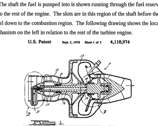
The shaft the fuel is pumped into is shown running through the fuel reservoir and then onto the rest of the engine. The slots are in this region of the shaft before the fuel can travel down to the combustion region. The following drawing shows the location of this mechanism on the left in relation to the rest of the turbine engine.
U.S. Patent Sept. 5, 1978 Sheet I of3 4,110,974
Figure 5: FIG. 1 Patent 4,110,974. Cross-Sectional View applied in gas turbine engine The orifices which are located on the shaft to offer varying speeds for the fuel regulation to take effect are opened and closed by solenoids. While this governor
invention focuses on the mechanical nature of the slots being made onto the shaft in order to control the fuel flow, the solenoids are operated electronically and therefore do add another control measure into this mechanism. The solenoids allow for there to be multiple governor settings depending on how many slots are made in the shaft and how many solenoids are applied to control their position.
In the description of the invention, a brief background gives a description on typical mechanical governors and electronic fuel governors. The mechanical governor which uses centrifugal force and some sort of mass balance and the electronic governor which monitors rotational speed to determine the fuel amount are claimed to be
expensive, complicated, and containing many moving parts which require maintenance to work properly.8 The proposed invention intends to improve upon these other two options because it is simple in nature and has fewer moving parts than any of the other two. The inventor also claims the invention can offer a much cheaper option and can be applied to
various types of engines.9 The claimed easy construction and maintenance, when compared to that of the other governors, also makes this invention more desirable to a more complex and maintenance intensive device.
This device, while not purely mechanical due to the presence of the solenoids controlling the slot openings, claims to make a more reliable and robust governor than the previous designs. The overall change of the governor from using fly weights under centrifugal force to the fuel itself as the regulating weight eliminates a large number of moving parts which cuts down on complexity and maintenance, both areas of possible failure in a system. The use of solenoids does add more complexity to the invention however as these devices now require a power source and a control system to regulate their function. These are included to allow for a number of governing speed options, as opposed to a single setting as seen in some of the classic examples. The added
complexity creates more parts which could potentially malfunction and fail, but now the governor has more versatility in its range of operations than before. Adding complexity for greater performance option is a trend which will be seen further in the other
mechanisms for fuel regulation.
While the two previous inventions focused mainly on mechanical innovations with regards to fuel governing, the next two are software based improvements in order to better govern fuel flow. The first is from Caterpillar Inc. which is a heavy machinery company. The invention described in patent 6,878,098 demonstrates selective governor usage for an engine. In this device, a control system is set up to select between different governors depending on the situations for optimal performance. The device contains a couple of sensors which can detect "a desired quantity of fuel, a desired quantity of air, and a desired quantity of an air/fuel mixture for the engine."'° These sensors then send a specified signal out to the control system, which then selects the appropriate governor for the situation. With the appropriate governor selected, the output can then match the conditions the engine is facing and as the situation changes, the sensors can detect the changes, and alter the governor selection accordingly.
9 Patent 4,110,974. pg. 1. 10 Patent 6,878,098. pg. 8.
The following drawing is a schematic to the sensor and control system proposed by Caterpillar.
L
L
I
---- -1 CONTROL1 ---I .I - OUT ... I r,--- GOVERNOR FUEL 2 I CONTROL2 I- -16Figure 6: FIG. 1 Patent 6,878,098. Block Diagram of Proposed Apparatus While stated in the description of this drawing that the block diagram is one possible application of this idea, the figure gives an accurate representation of the entire concept. The patent does not propose any new mechanical governors, but rather uses the current ones. It instead applies a new method to allow for selective control between multiple governors, as opposed to being restricted to one governor for all conditions encountered during the use of the engine.
In the background description in the submitted patent, the inventor describes how "most engine governors are configured to determine a quantity of fuel that will regulate either engine power or engine speed."" The example given is a truck engine used in highway transportation. The truck must have fuel regulation whether it is carrying a load or not. Whether a power governor or speed governor is employed with the truck engine, there exists in both cases an unnecessary level of power created by the engine and governor. The background also states the governors required to regulate engine speed and engine power are separate as the fuel levels required for both governors are different. The design of engines then must select one of the two governors and accept both the advantages and disadvantages of the governor.'2 The invention claims to allow the
n1 Patent 6,878,098. pg. 1.
manufacturer to now have the advantages of both of these types of governors while eliminating or reducing the disadvantages.
This invention does not create a new governor but introduces a new control system for already existing governors. With the claimed improvements, an engine system would now reduce unnecessary fuel consumption and improve the performance for both speed and power governing. Here a simple software control system will increase performance. There is no mention in the description or claims that this is a simplifier or increases reliability however. The invention creates an engine system with twice as many parts due to the addition of another governor which will create more potential mechanical failure areas. The resulting engine system has more complexity, but it also increases performance under a wider range of conditions than with a single power or speed governor.
The final patent on fuel control is a fuel injection quantity control system for a diesel engine which was developed by Nissan Diesel Motor. The invention described in this patent uses an electronic-hydraulic governor to control electrically the amount of fuel
injected into the engine at given conditions. When the driver applies full acceleration to this engine system, a DC linear motor moves the control rack which engages the fuel injector to give the appropriate amount of fuel. Sensors are in place to detect the rack position during operation in order to determine the optimal level of fuel to inject. 13 As opposed to the other governors explained, which were mechanical, this system employs an electronic-hydraulic governor, where the invention claimed is the control system for this type of governor. The following figure is a schematic illustration of the described invention.
2 9
3
5
Figure 7: FIG. 1 Patent 5,937,824. Schematic Illustration of Invention
The DC motor controlling the position rack is represented by label 15. It controls the link 19 which is connected to the control rack 17. The control rack engages the plunger within the fuel injection pump which is not pictured. The sensors 21 send the signals to the control unit 13 about the rack position during operation of the accelerator.14
The control unit uses not only the signals from the rack position sensor, but also signals from an acceleration sensor and an engine speed sensor. With all of these signals, it calculates the amount of fuel needed to operate the engine while driving.15 The control
unit then can specify how much the DC motor needs to move the control rack in order to inject the correct amount of fuel.
The main purpose stated for creating this invention was to prevent an overshoot of the control rack. This overshoot would cause an unnecessary increase in the amount of fuel injected into the engine during operation and cause the generation of black smoke.'6
By sensing the position of the rack during operation and signaling the control unit, the fuel injection can be controlled even when the driver applies full acceleration to the vehicle. With the invention, the throttle is no longer simply dependent on just the driver's input but is controlled by previous control rack position, engine speed, and acceleration. The generation of black smoke, which is harmful to the environment, is reduced, and also the amount of wasted fuel is reduced.
14 Patent. 5,937,824. pg. 3.
15 Patent. 5,937,824. pg. 2.
These reductions enhance the performance of the diesel engine in operation. The invention here is a software control system for an electronic-hydraulic governor. Instead of replacing the entire governor, or adding additional governors, the system simply has a new control installed to help regulate the operation of the fuel injector. Now the
performance can be improved by simply using the appropriate software to interpret the signals sent to the control unit. The governor system here focuses on the ability to adapt to varying conditions and still have optimal fuel consumption. It does not focus on robustness or the reliability of the system, and those characteristics of the system would have to be further analyzed. The final result of this invention is an engine which requires no more input from the driver, but can optimize fuel consumption by monitoring various operations of the engine.
In these inventions, each tried to improve the governor of an engine and
subsequently the fuel consumption during operation. The first two inventions focused on reliability and simplicity. These two used primarily mechanical solutions to make the governor more reliable and stable during operation. While one employed the use of solenoids to operate the opening and closing of slots in its mechanism, the main claim was to reduce the number of parts and simplify the design, making the device more robust. The final two patents employed electronic control systems which used input signals from sensors to determine the appropriate amount of fuel to be used in the engine. In these devices, the main claim was to improve performance, not to reduce complexity or the number of parts. Components were added to already existing systems in order to improve the performance of the engine. No mention of robustness or reliability was made in the claims made by these inventors.
Driving force and torque distribution
The next case of patents will look at solutions to driving force and torque
distribution. In a vehicle, power must be distributed from the engine to the wheels. The system of transferring power must be reliable, but there exists room to enhance
performance in various driving conditions. The power is distributed from one source to two or four independent wheels. These wheels can either be under the same conditions as
when driving straight on the highway, or they could be experiencing different conditions, such as in hard turning or in varying weather conditions. In both cases, the power distribution system must be able to operate under those conditions to keep control of the vehicle in the hands of the driver.
The two patents which will be evaluated are a differential gear mechanism patented in 1958 and an electromagnetic clutch structure developed by Honda. Each of these inventions is a system which distributes power from the engine and transmission to each of the wheels and can react to varying conditions for each of the wheels. One achieves this through an entirely mechanical device, while the other employs electromagnetic clutches with a control system.
The first invention was claimed by Vernon E. Gleasman of Cleveland Heights, Ohio. His invention is "an improvement in differential gearings of the type sometimes referred to as 'positive drive.'"17 His statement in the beginning of the patent
summarizes the purpose of the invention.
"The ultimate objective, which has never been obtained prior my invention, has been to develop a mechanical device which will distribute torque equally to the two driven traction gears under any condition of relative motion as dictated by ground speed but never permitting torque to be applied to any one wheel in excess of the available traction without causing both wheels to slip simultaneously."18 In his patent, the inventor explains the disadvantage of having more power applied to one wheel when either turning a sharp corner or operating under adverse weather conditions. He claims that having power applied unequally can cause undue stress and wear on the gear system. A new system of gears, with side gears which are worms and transfer gears are utilized to help keep power equally distributed and the differential action free at all times.19
17 Patent. 2,859,641. pg. 1.
18 Patent. 2,859,641. pg. 1.
Figure 8: FIG. 10 Patent 2,859,641. Perspective View of Possible Use of Invention This drawing shows the invention applied to a drive system on a vehicle. The differential is located on the left gear system, with a cutaway view of the cylinder and its
inner gears. While in this claim the invention is only applied to two driving wheels, the differential can be applied to a four wheel drive system. The inventor also claims his invention will be able to fit within the existing differential housings so as to not require as many new parts for the vehicle. Also the use of three sets of transfer gears and posts which act at part of the gear case and act as bearings for the transfer gears allow the assembly to have increased strength but also a reduction in size.2 0
The advantages of this gear system is that it allowes equal distribution of power for whatever driving conditions. The gear design has few parts and does perform as long as the gears and housings do not structurally fail. The design also helps eliminate the stresses and wear previously encountered in older designs. The design still sees use today, even in modern military trucks such as the Humvee. With few parts and reliable function, this design is quite robust and also can perform in a wide variety of conditions. The operation depends on the integrity of the structure and provided the parts are manufactured with a high standard of quality, the device will last a long time.
An alternate design to this purely mechanical device for power distribution is the one claimed by Honda. Their invention uses an electromagnetic clutch structure to selectively operate clutches on the right and left wheels of a vehicle. These clutches are able to transmit torque from the outer turning wheel to the inner wheel in order to have
20 Patent. 2,859,641. pg. 6.
stability while the vehicle turns. The devices each contain a coil, a core to house the coils, armatures to hold the core in the correct position and frictional engagement members inside the core.21 These clutches are all operated by a control unit which contains a microcomputer. With this device, each of the wheels is able to have torque applied individually and independently according to the given conditions during operation.
FIG.2
Figure 9: FIG.2 Patent 6,637,572. Clutch System
The above figure shows the embodiment of the device with the clutch systems able to be independently engaged. The clutches are engaged depending on the turn of the vehicle to allow for proper power distribution through the turn. The engagements are controlled by a microcomputer which uses a number of variables to determine the proper power distribution. Engine torque, engine rotational speed, vehicle speed, and steering angle are all processed by the software to allow for proper control of the left and right electromagnetic clutches.2 2 Unlike the mechanical solution, which can only react to the rate at which the wheel is turning on the ground, this system can analyze many of the important factors of not only the wheels but of the rest of the power train to allow for appropriate power and torque distribution.
21 Abstract. Patent 6,637,572. 22 Patent. 6,637,572. pg. 3.
Both of these systems attempt to achieve the same goal of power distribution to the driving wheels during any driving condition such as hard turns and slick roads. The purely mechanical solution achieves this with a unique design of gears which allow the wheels to have equal power distribution. It allows the wheels to be driven at different rates for corners while not allowing slipping or loss of traction. The design is inherently robust due to its few number of parts and simple strong design, and it has been proven with its existence and use over a few decades. The design proposed by Honda proposes to achieve the same results. With its computer control and independent clutch control for each wheel, the system is able to react and adapt to any condition, provided it has the proper programming. The flexibility of this design is much higher because different software programs can be installed and updated as more tests are run. Also other information about the vehicle's operation is used in calculating the appropriate
distribution. These all allow for increased performance, but do increase the complexity of the construction. Each wheel now depends on a computer controller and an
electromagnetic clutch to operate properly. If a failure occurred in any of these, whether mechanical or electronic, the vehicle's stability could falter and cause serious damage. In the purely mechanical design, only a failure in gears would cause the vehicle to be
inoperable. Here, increased performance has come at the cost of a more complex design with an increase in possible failure modes.
Valve timing
The last case will look at mechanisms which deal with valve operation and timing in engines. Valve timing is an element of the engine's operation which can be optimized and altered to change performance. Without proper timing, the engine's operation can be adversely affected and possibly fail, leading to damage to the engine. The appropriate timing can increase power and torque in a vehicle and be better at conserving gas. Also, certain valve timing setups are more effective at lower and higher rpm's. In recent years, many of the automotive manufacturers have invented new mechanisms and systems to operate the intake and exhaust valves, but the one most prevalent in automobiles today is almost the same in most vehicles.
The standard valve timing system utilizes a camshaft, rocker arms, and valves which allow for the fuel/air mixture to enter and exhaust to exit. The camshaft pushes on the rocker arms or rods connecting to the rocker arms to operate the valves opening and closing. The camshaft is turned by a timing belt or chain which is powered by the crankshaft of the engine. This design, while simple and relatively robust, does not allow for a significant amount of adjustment, other than the speed at which the shaft is rotated, which is dependent on the engine speed. Other than completely replacing the camshaft, there is no way for the valve timing to vary with this design. The next three patents are inventions which provide ways to change the valve timing during operation. Two of them still employ camshafts with methods to change the valve timing with them, and the final one is an electrohydraulic system without a camshaft designed by Ford Motor Company. These patents will show in their descriptions and motivations the continued trend of mechanical elements being employed for robustness and electronic control units being used for more performance and versatility.
The first patent is a variable valve timing apparatus developed by Honda, patented in 1985, for use in a four-cycle internal combustion engine. The device contains two camshafts in a housing supported above the cylinder which are able to be selected for high and low rpm's for optimal timing. The apparatus is able to switch so that one camshaft is in contact at a time with the rocker arm.2 3 The following drawings show the
device in a couple of its stages.
Figure 10, 11: FIG.7 and FIG.8 Patent 4,535,733. Sectional View in Varying Positions The rocker arm has a portion which is in contact with the low speed cam when the clutch is in the off state. When the clutch is in the on state, the rocker arm is in contact with the high speed cam. The camshaft holder, as pictured, is controlled by an arm
control and pivots around one of the camshafts. When it is rotated, the other cam is either engaged or disengaged from the appropriate side of the rocker arm.
In the background, this patent discusses other examples of variable valve timing which it claims are too complicated. One was a system where the rocker arm has a variable pivot point, and the other had a number of rocker arms to be engaged when appropriate to alter the timing of the engine. The inventor described attempts to
"overcome the above-mentioned drawbacks and to provide an improved variable valve timing apparatus." The patent also goes on to claim this device is a simple and compact solution to the variable valve timing problem. 24 The invention described uses mostly mechanical solutions to improve valve timing. The valve timing is still operated by a camshaft, a proven method. While the selection between the two camshafts will require some sort of controller, the structure itself strives to be simple and maintain a level of robustness.
The next patent was also developed by Honda but patented twenty years later in 2005. This invention again uses a camshaft system for valve timing, but instead of utilizing two camshafts which can be selected for contact with the rocker arm, it uses a single camshaft with a adjustable drum. Also, the device allows for a more continuous changing of the valve timing, as opposed to simple two settings to choose from, which the previous design offered. The design focuses on the intake valve of the internal combustion engine, and while the drum may extend axially across to the exhaust valve cams, it can be altered to prevent interference.2 5 While this design does offer a wider
range of valve timing options, it still consists of a mechanical solution to alter profile of the cam in contact with the rocker. The invention claims to not only avoid complexity in its design, but also increase performance of the engine.
The device consists of a camshaft with a drum attached to it which can be varied within a certain range. In essence, the profile of the cam is able to be altered for a specified range. The drum is turned by a control rod with a pinion, which is then powered by an electric motor.2 6
Figure 12: FIG.1 Patent 6,968,819. Partly Broken Away Side View of Invention The previous device that this invention intends to improve upon also achieved the goal of varying the valve timing in a smooth and continuous fashion. The older patent
25 Patent. 6,968,819. pg. 2. 26 Patent. 6,968,819. pg. 2.
i I
had a camshaft with a varying profile in the axial direction. As the need for a different intake valve sequence arose, the camshaft was moved axially and allowed the new profile to take control of the rocker and valve's motion and timing. The disadvantage of this design was the need to move the camshaft in an axial direction as well as rotationally. The other downfall was the complex cam profile which would need to be created on the shaft itself, which would be expensive to manufacture. However, even with all of these disadvantages, the invention did allow for not only valve lifting to be continuous, but also for the process to be varied.2 7
Stated in the background of the second device, the primary object "is to provide a variable valve actuating device which allows both the valve lift and valve timing for an
engine valve to be varied in a continuous manner without unduly increasing the complexity and manufacturing cost of the valve actuating device."2 8 Reducing
complexity and subsequently the cost of manufacture are factors which do increase the robustness and reliability of a design. However, this design is unique in that it is a proposed improvement on a line of inventions which intend to improve performance. The second object of the design is to create a device which can "optimize the
performance of the engine."2 9 This objective follows with the trend of previous inventions which sought to also improve engine performance through valve timing modifications. The current invention does still hold this objective and does require some sort of control for the electric motor which powers the drum. The primary goal is to overcome the complexity of previous designs. For this patent specifically, the goal was simplicity, and a mechanical solution was pursued.
The final patent, submitted by the Ford Motor Company, forgoes the usual camshaft in valve timing and instead uses an electrohydraulic camless valvetrain system which can selectively open and close each engine valve. In this particular system, each
engine valve has a rotary valve, operated by a motor, which can allow high and low pressure to enter a specific volume.3 0 They idea of using a hydraulic system to control valve timing has existed for some time now. In a patent submitted by Caterpillar in 1966,
27 Patent. 6,968,819. pg. 1. 28 Patent. 6,968,819. pg. 1. 29 Patent. 6,968,819. pg. 2 30 Abstract. Patent 5,562,070.
a design was made with the purpose of "adjusting the angular phase relationship between, .. shafts for the purpose of varying the timing of an internal combustion engine or the like."31 The hydraulic portion of Ford's system is different in its mechanical design, but the hydraulic system, along with some other ideas, have been proposed to eliminate the use of a camshaft to help increase the performance of valve timing in an internal combustion engine.
The invention background stated in the patent describes the rising use of
microprocessor control in motor vehicles, which are being used throughout automobiles to control many different systems. The patent also states "increased confidence in hydraulic as opposed to mechanical systems is making substantial progress in engine systems design possible."3 2 Previous hydraulic systems were not controlled using microprocessors as they did not exist at the time, but Ford argues since a control system is now available which can handle the complexity of engine valve timing, the system should be designed. The patent clearly states that "the enhancement of engine performance to be attained by being able to vary timing, duration, lift, and other
parameters of the intake and exhaust valves' motion in an engine is known in the art."3 3 The patent further states by allowing independent control of each engine valve, engine performance can be optimized and also have much greater flexibility that previous cam and camshaft driven valve timing systems.
31 Patent. 3,258,937. pg. 1.
32 Patent. 5,562,070. pg. 1. 33 Patent. 5,562,070. pg. 1.
FIG. 5
Figure 13: FIG. 1 Patent 5,562,070. Schematic Diagram showing Single Engine Valve. The above figure shows a diagram which contains the engine valve itself and the hydraulic control systems. Rotated by an electric motor, the hydraulic valve is able to selectively allow the pressurized hydraulic fluid to enter and exit the engine valve
component and control its opening and closing. The rotary valve was designed to replace previous systems which employed a pair of solenoids to control a single engine valve. A previous invention, U.S. Pat. No. 5,255,641, utilized two solenoids, where one opened the valve and the other closed the valve. Each valve requires two solenoids, and while the design did provide the necessary function and flexibility for valve timing, the large number of solenoids required for one engine became too large, especially with the multi-valve engines. 34
The following figure shows the rotary valve itself and how it controls the flow of hydraulic fluid to the engine valve.
34 Patent. 5,562,070. pg. 1.
r---3,4
!
FIG.2
Figure 14: FIG.2 Patent 5,562,070. Sectional View of Rotary Valve. The valve allows for high and low pressure hydraulic fluids to enter the engine valve at the appropriate times depending on the rate of rotation or the valve. The use of a rotating hydraulic valve was chosen to eliminate the need for multiple solenoids per engine valve. The design here also improved upon a previous rotary hydraulic actuator patented. This invention states its desire to create a valve which is as efficient as possible in order to reduce power needed and the size of the system. 35
In this patent, the specific improvement being claimed is the rotary valve system. The object of the invention is to improve the camless variable valve control system by employing the above rotary valve which is able to maximize the fluid carrying capacity. The system also eliminates the need for solenoid control which is too complex and large for engines with multiple intake and exhaust valves. The rotary valve design claims to reduce size and weight of previous designs and therefore reduce the necessary power needed by the electric motor to turn the valve.3 6 All of these mechanical improvements
on previous hydraulic inventions create a simpler system requiring less power and increases the robustness of the design.
35 Patent. 5,562,070. pg. 1. 36 Patent. 5,562,070. pg. 2.
While the aim of this patent is to mechanically improve the rotary valve contained controlling the hydraulic flow, the entire electrohydraulic system strives to optimize engine performance. The mechanical improvements are to improve the reliability of the proposed system, but do not attempt to remove any of the flexibility which is being sought after. Using a microprocessor in conjunction with the electrohydraulic timing system allows for a huge increase in the flexibility of the engine's operation and performance. The range of operation is no longer limited to one or two camshafts or a range of cam profiles. Instead, a computer program can be installed to alter the timing for whatever the conditions demand. The entire system is more complex than previous camshaft designs, simple because each engine valve is now operated independently and requires individual control. While a camshaft simply controls an entire row of intake and exhaust valves, the system proposed by Ford will need a more complex system in order to maintain even the same level of performance offered by existing camshaft timed engines. Even within designs seeking to achieve optimal engine performance, the need for
robustness and reliability exists, and in this patent the solution was primarily a mechanical one given the hydraulic nature of the timing system.
All three of these patents contain both mechanical elements and electronically controlled elements. However, once these components are isolated an analyzed, the motivations behind each can be seen. The devices contain software controllers because the increased performance and flexibility of the operation. The desire for reliability still exists in these devices, the mechanical movements required for the operation, controlled by software need to operate reliably in order to achieve a greater level of performance.
Conclusion
With each of the three cases, both mechanical and software solutions were observed as well as the motivations and intentions behind them. Either through the description of past inventions or the stated claims of the actual invention itself, an insight was gained into the reasons for selecting the solution. In the case of fuel governing, a purely mechanical solution claim less complexity and more reliable function by minimizing fuel leakage. The second patent, as well, suggested for a more reliable
device in its description and background. The other two inventions pursued more complex systems, with sensors and controllers, in order to increase and optimize performance.
The second case of power and torque distribution had a purely mechanical solution developed decades ago compared against a heavily software controlled solution developed recently. While the objective of power and torque distribution was the same, the approaches were quite different. The electromagnetic solution proposed by Honda was inherently more complex since it required a series of components for each driven wheel. The mechanical differential consisted of only a series of gears, but was limited to certain road conditions. The Honda solution provided independent control and power, but also had many areas for possibly failure, and since its development is only recent, it has had little time to be tested rigorously. The last case of engine valve timing had mostly patents with an integration of both mechanical and software components. While the improvements stated in the patents were mostly for the mechanical portions of the system, the motivations and reasons for changing to a more software controlled system, especially in the electrohydraulic system proposed by Ford, were stated in the
background of the inventions.
The mechanical solutions were mostly chosen, according to the patent literature, for their greater simplicity and ability to perform reliably. The software solutions and components were put in place to greatly increase the performance of a system. They added flexibility and a wider range of operation than previously experienced. What was not stated in these patents was that the mechanical solutions did not provide increased performance or flexibility or that software solutions decreased reliability and robustness of the design. These statements were never explicitly stated in the patent literature and would be hard to conclude from these inventions alone, as some of these inventions have not been adequately tested.
The review of patent literature offers only a small insight into why developers choose to use either mechanical or software solutions. In the patents, the inventors described the problems and issues their devices could possibly fix and not the problems they could cause or could not solve. To more fully understand the ability of an invention to either add robustness or increase its flexibility, more research would have to be
conducted. Analysis of the testing of a device, performance in real world conditions, and the overall performance of the device when actually applied and used would have to be observed. Some inventions which are patented would actually have to be physically constructed in order to observe how they perform. The insight gained from patents provides only the first step in analyzing the reasons and trends behind choosing a particular solution.
Bibliography
1. Clausing, Don and Frey, Daniel D. "Improving System Reliability by Failure-Mode Avoidance Including Four Concept Design Strategies." Systems
Engineering, Vol. 8, No. 3, 2005. Wiley Periodicals, Inc. 2005. pgs. 245-261. 2. U.S. Pat. No. 5,234,014.
3. U.S. Pat. No. 4,110,974. 4. U.S. Pat. No. 5,937,824. 5. U.S. Pat. No. 6,878,098. 6. U.S. Pat. No. 2,859,641. 7. U.S. Pat. No.6,637,572. 8. U.S. Pat. No. 4,535,733. 9. U.S. Pat. No. 6,968,819. 10. U.S. Pat. No. 3,258,937. 11. U.S. Pat. No.5,562,070.