The MIT Faculty has made this article openly available.
Please share
how this access benefits you. Your story matters.
Citation
Wright, J., and S. Shiraiwa. “Antenna to Core: A New Approach to
RF Modelling.” Edited by J. Hillairet. EPJ Web of Conferences 157
(2017): 02011 © 2017 The Authors, published by EDP Sciences
As Published
http://dx.doi.org/10.1051/epjconf/201715702011
Publisher
EDP Sciences
Version
Final published version
Citable link
http://hdl.handle.net/1721.1/113299
Terms of Use
Creative Commons Attribution 4.0 International License
Antenna to Core: A New Approach to RF Modelling
J. Wright and S. ShiraiwaPlasma Science and Fusion, Massachusetts Institute of Technology, Cambridge, MA, USA
Abstract. A new technique for the calculation of RF waves in toroidal geometry enables the simultaneous incorporation of antenna geometry, plasma facing components (PFCs), the scrape off-layer (SOL) and core propagation [Shiraiwa et al, “HIS-TORIC: Extending core ICRF wave simulation to include realistic SOL plasmas”, Nucl. Fusion in press 10 (2017)]. The calculation of antenna coupling has been traditionally performed separately from those of core propagation whereas this method allows them to be combined permitting the modelling of such phenomena as waves reflected from plasma-vacuum boundary or cyclotron resonances back to the antenna. Calculations with this technique also naturally capture wave propagation in the SOL and its interactions with non-conforming PFCs permitting self-consistent calculation of core absorption and edge power loss.
1 Introduction
In modelling and theory of radio frequency (RF) fields in different frequency regimes, the core and edge plasmas have been treated in a separate manner. High fidelity core ion cyclotron and lower hybrid (LH) codes use sophisticated dielectric models for the confined plasma but model the scrape off layer and plasma facing components more simply often with uniform cold plasmas and conducting walls or simple vacuum regions [1-4]. Antenna coupling models will use very accurate models of the antenna structures but calculate the plasma impedance with one dimensional half infinite models [5,6] and typically do not model wave propagation into the plasma. There is a growing realization in the community of the importance of the connection between these two regimes [7-12].
The finite element method (FEM) and the spectral approaches to simulation of ion cyclotron (IC) waves in toroidal plasmas each have strengths and weaknesses. For example, the spectral approach (e.g. TORIC[1] and AORSA [2]]) has a natural algebraic representation of the parallel wavenumber and hence the wave dispersion model but does not easily represent complex geometries present outside the last closed flux surface, whereas the FEM approach (e.g. LHEAF [13,14]) naturally represents arbitrary geometries but does not easily represent thermal kinetic corrections to the plasma dispersion. The two domains: thermal core with flux surfaces and cold edge plasma with open field lines may be combined in such a way that each approach is used where it works naturally. Among the possible ways of doing this, we demonstrate the method of mode matching. This method provides an easy way of combining the two linear systems without significant modifications to the separate codes. We will present
proof of principal cases and initial applications to minority heating.
The main motivating insight is that the core plasma region that is assumed to have closed flux surfaces requires a hot plasma dielectric while the open field line region in the scrape-off layer needs only a cold plasma dielectric. Spectral approaches work well for the former and finite elements work well for the latter. The two approaches are combined with a domain decomposition technique that constructs the solution from Green's functions obtained from a core spectral code, TORIC [1], and an edge finite element code using COMSOL [15] or MFEM [16], operating in their respective regions. The validity of this process follows directly from the superposition principle of the linear Maxwell’s equations making this technique exact. The method is independent of the codes or representations used and works for any frequency regime.
The outline of this paper is as follows: we will briefly review the method of domain decomposition to separate the solution of wave propagation in the scrape off layer (SOL) from the core as presented by Shiraiwa and Wright [17-20]. We will then discuss extensions of this model to include resistive dissipation in the SOL to calculate core heating efficiency. In the next section, we will demonstrate applications to minority heating in Alcator C-Mod and high harmonic heating in NSTX-U will be presented in single pass and multi-pass regimes. Finally, we will discuss extensions of the method to three dimensions and future applications.
2 Description of the method
In the frequency domain Maxwell’s equations are given by:
𝛁𝛁 𝛁 𝛁𝛁 𝛁 𝛁𝛁 𝛁 𝛁𝜔𝜔𝑐𝑐22{𝛁𝛁 𝑬4𝜋𝜋𝜋𝜋𝜔𝜔 (𝑱𝑱𝑷𝑷𝑬 𝑱𝑱𝑨𝑨)} (1) 𝑱𝑱𝑷𝑷𝛁 𝝈𝝈⃡ [𝑓𝑓0(𝒙𝒙𝒙 𝒙𝒙𝒙 𝒙𝒙⊥𝒙 𝒙𝒙∥)] ∙ 𝛁𝛁, (2) where JP is the plasma current response to the electric RF field, E, as determined by the plasma conductivity, . The antenna current, JA, gives the source of RF wave energy. In typical RF full wave codes, it is an idealized current strap without detailed antenna structures or limiters [1, 2]. The Vorpal code [8,9], this publication] is an exception that uses a finite difference mesh to model the complex antenna geometry and includes cold plasma wave propagation from the antenna into a partial region of the core plasma. Other recently developed codes also focus on the cold plasma wave propagation near the antenna with perfectly matched layers (PML) at the domain boundaries such as RAPLICASOL [21,22]. Such outgoing boundary conditions as PML or absorbing boundary layers preclude the study of possibly important physics effects such as the reflection of waves back towards the antenna, far field sheath effects [23,24], and the modelling of scrape-off layer (SOL) propagation and collisional dissipation of coupled wave energy.
Here, we present a method to seamlessly connect the physics of hot plasma core propagation codes with the detailed antenna models such as used by TOPICA [6] including SOL propagation and dissipation. Maxwell’s Equation’s as typically used in plasma physics with a linear dielectric response support the superposition principle. A consequence of this property is that an RF (radio-frequency) problem described by Eq. (1) along with boundary conditions (BCs) may be decomposed into separate solvable systems with BCs that while differing from the original system are equivalent to it. This leads to a domain decomposition technique that is described in detail in Wright [17] and Shiraiwa [18-20].
The tokamak plasma is separated into two domains: inside the last closed flux surface a hot plasma dielectric is used with a spectral decomposition and outside a finite element representation with a cold plasma dielectric is used. The two solution domains are connected by an admittance condition at the matching boundary – the last closed flux surface – with the approximation that no significant kinetic flux is present there. Solutions in the two domains are built up from a family of Green’s functions resulting from a source electric field on the boundary that is a pure poloidal mode, E~exp(im), for each tangential component. Continuity of the tangential electric field requires that the modal amplitudes of the inner and outer solutions are the same. Continuity of the tangential magnetic field is given by an admittance equation that determines the amplitudes of the solution. Mathematically, this is given by Eqns (3) and (4):
∑ 𝑎𝑎𝑚𝑚𝐸𝐸𝑚𝑚core
𝑚𝑚 𝛁 ∑ 𝑎𝑎𝑎𝑚𝑚𝐸𝐸𝑚𝑚 𝑚𝑚edge (3) ∑ 𝑎𝑎𝑚𝑚𝑚𝑚 𝐵𝐵𝑚𝑚core 𝛁 (∑ 𝑎𝑎𝑎𝑚𝑚 𝑚𝑚𝐵𝐵𝑚𝑚edge𝑬 𝐵𝐵𝑚𝑚ant), (4) where 𝐵𝐵𝑚𝑚ant is the contribution of the antenna magnetic field’s mth poloidal mode to the matching boundary. For
unit drive electric field, 𝐸𝐸𝑚𝑚, the resulting magnetic field, ∑ 𝐵𝐵𝑚𝑚′𝑚𝑚′ , is the admittance response (cf. Fig. 5 in Shiraiwa [19]).
There are several advantages to this approach. We may use an existing core code with a kinetic dielectric that has been well verified and validated such as TORIC [1]. The edge finite element model may represent complicated limiter structures, even the antenna itself, and straightforwardly supports other boundary conditions such as a rectified sheath [7]. The admittance equation solved to couple the two systems has only a degree of freedom equal to the number of poloidal modes used in the coupling while the core and edge solutions are of one dimension higher (in three dimensions the order of both is raised by one more dimension). And the core and edge solutions are only coupled via this admittance equation. A consequence of this is that the core and edge responses may be recalculated independently; for example, if the antenna structure or phasing was changed it would only require recalculation of the edge response of the coupled system. The overall computational cost of the entire system is comparable to a normal standalone solution from a core code. All the mode responses are computed in a single simulation by replacing the normal boundary condition associated with an antenna strap by an array of boundary conditions each one associated with one of the driving poloidal modes. The consequence of this is to add a matrix-matrix product in addition to the normal matrix inverse in place of a matrix-vector product. This approximately doubles the calculation time. If we include the degrees of freedom (DoF) of the edge solver, the total DoF is approximately doubled compared to the original core solver for only ½ the computational requirement one would expect because of the domain partitioning. This is because for a direct solve scaling as (DoF)3 we would expect a factor of 8 increase in computation for doubling the DoF but instead have two regions with the same as the original DoF but requiring approximately twice the computation.
3 Application to edge losses
An important capability of this model is the capture of edge dissipation in the scrape of layer (SOL) or rf sheath rectification on plasma facing components. In this section, we demonstrate the role of Spitzer resistivity in dissipating wave energy in the SOL. In Alcator C-Mod, minority heating in Deuterium plasmas may use either a Hydrogen or a Helium-3 minority species. Observed heating efficiencies for these two cases differ significantly [25]. Including the SOL propagation and dissipation explains the difference. In NSTX, surface wave excitation has been shown [10] to be an issue in current drive efficiency by high harmonic fast waves when the SOL density is above the fast wave cutoff. We show that significant amounts of wave power are lost in the SOL and that the wave propagation is more limited with realistic geometry and SOL densities than shown previously [10].
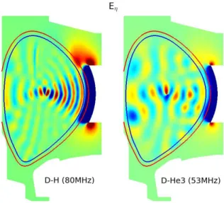
Fig. 1. Real part of the poloidal () component of the wave electric field. A comparison of strong D-(H) (left panel) and weak D-(He3) (right panel) absorption in Alcator C-Mod minority heating scenarios. Minority concentration in both cases is 5%. Simulations used resolution of 127 poloidal modes and 240 radial cubic finite elements. The light line border around the core plasma is the matching layer for the inner and outer solutions and the thick red line is the plasma – vacuum boundary.
3.1. Strong and Weak core absorption
In Fig. 1, D-(He3) in the left panel demonstrates weak single pass absorption. The waves reflect off the walls multiple times setting up standing wave patterns and fill the core plasma volume. In contrast, the D-(H) plasma shows strong absorption and focussing of the ICRF waves in the center of the plasma cross section. The antenna loading for both scenarios is comparable (14.5 and 16 respectively from model calculations) but experimentally, the D-(H) scenario is much more efficient at heating the plasma. A competing loss mechanism provided by resistive dissipation in the SOL enables the calculation of a core heating efficiency.
Fig. 2. Highlight of SOL collisional power loss for two minority heating cases in Alcator C-Mod on a logarithmic scale. 95% majority D, 5% minority He3 or H, B=5.254 T, ne0=5x10¹⁴, Te0=4 keV, Tminority=120 keV, f=80 MHz, nphi=10.
To the edge FEM model surrounding the core plasma we add a 2.5 cm SOL with a cold plasma dielectric. A finite electron temperature of 15 eV is retained in a collision frequency calculated from Spitzer resistivity.
The density is 4x1019cm-3 at the top of the pedestal and has a minimum of 2x1019cm-3 at the bottom. The density in the SOL everywhere is above the lower hybrid resonance value and the fast wave cutoff. The D-(H) minority case predicts that 10% of the wave power is dissipated in the scrape-off layer and 90% in the core. For D-(He3), 50% is lost in the scrape-off layer. These two heating efficiencies of 90% for D-(H) and 50% for D-(He3) are in the same range as experimental observations [25] for these minority heating scenarios. Figure 2 shows the collisional power deposition in the SOL in two dimensions. In both cases, there is power deposited in front of the antenna. In the D-(He3) case we see SOL power loss on the high field side of the cross-section indicating that some of the ICRF power passes through the plasma and is deposited in the SOL near the inner walls. This could indicate a possibility of far field sheath power losses and localized plasma facing component (PFC) heating as well.
3.2 Surface waves
For some plasma conditions in high harmonic fast wave current drive experiments on NSTX, much of the coupled wave power does not appear in the plasma core [10]. When the density in the SOL is above the fast wave cutoff density, surface waves may propagate between the antenna and the last closed flux surface (LCFS). In Fig. 13 from Bertelli [10], as the density is raised above the fast wave cutoff in AORSA full wave simulations, the region outside the LCFS is filled with a standing wave pattern. These simulations used a constant density everywhere outside the LCFS in a rectangular wall. We reproduce this case in Fig.3 using the actual limiter geometry and constrain the density to be constant on field lines outside the LCFS with a 3 cm SOL at the midplane.
Fig. 3. NSTX HHFW with SOL and collisional losses. Density has 5 cm SOL gradient. Nphi=-12, f=30 MHz, ne0=3.7x10¹³, Te0=1.1 keV, and B=0.55 T. Deuterium plasma with Deuterium beams.
The enlargement of the fields around the antenna show a limited area of fast wave propagation in the SOL. This is a consequence of the wave being cutoff by low in the shadow of the antenna limiters. The density in the SOL is modelled by diffusing density along open field lines from the last closed flux surface. The waves in this
NSTX case are in a single pass absorption regime but the presence of relatively high plasma density outside the LCFS permits some fast wave propagation in the immediate area of the antenna. This is sufficient for 20% of the coupled power to be lost in the SOL to collisional damping. In contrast to the results shown in Bertelli [10], the wave propagation is fairly localized due to the higher fidelity modelling of the SOL and limiter surfaces. This could be important in experimental comparisons with diagnostics measuring RF fields in the SOL, for example.
4 Extending to three dimensions
The domain decomposition technique used in these two dimensional simulations trivially extends to full three dimensional simulations. Instead of constructing an admittance system of poloidal mode responses for a single toroidal mode, the admittance matrix includes a spectrum of toroidal modes as well. In this case, the size in NmxNn where Nm is the number of poloidal modes and Nn is the number of toroidal modes. The matrix then has the form of dense blocks representing poloidal coupling along the diagonal and more spare lower magnitude blocks off the diagonals representing toroidal coupling as seen in Fig. 4.
Fig. 4. Edge coupling admittance matrix for three dimensional ICRF simulation of Alcator C-Mod. 1342 independent full wave solutions by the each of the full wave codes for the core and edge plasma response are used to solve the full admittance system.
If we may assume the core plasma is axisymmetric for a tokamak, then the core solutions may be generated one toroidal mode at a time. The edge solution is fully three dimensional and any non-axisymmetric structures in the edge plasma such as the antenna result in finite cross coupling between toroidal modes. As a result, when solving the matching for the core – edge interface, the core toroidal modes are also coupled together by edge asymmetries in the final solution.
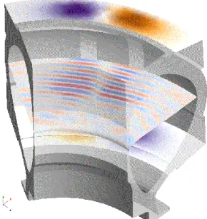
Fig. 5. A 60 degree toroidal slice of a full three dimensional simulation of Alcator C-Mod showing the left hand polarized component. 95% majority D, 5% minority He3 or H, B=5.254 T, ne0=5x10¹⁴, Te0=4 keV, Tminority=120 keV, f=80 MHz, nphi=[-30, -24 … +24, +30].
For the case shown in Fig. 5, we choose to break the edge response calculation into six 60 degree toroidal wedges. As a consequence, only the sixth toroidal mode harmonics (-30, -24 … +24, +30) need to be calculated for the core response. This is the same symmetry technique used in previous stellarator full wave calculations [3]. Figure 5 shows a 60 degree slice of the reconstructed full three dimensional simulation including antenna straps and edge propagation. A midplane slice of the RF fields shows the toroidal extent of the waves launched by the two straps The two straps are phased 180 degrees apart for heating and this is evident in the RF field perpendicular to the wall of the straps shown at their endpoints. The only asymmetry in the edge plasma for this simulation is from the antenna straps. Stellarator simulations are also possible using the algorithm presented in this paper. To capture the toroidally periodicity of stellarators, a code such as AORSA [2] or SCENIC [26] could be used for the core response.
5 Conclusions
In this paper, we have presented a core to edge RF model that is capable for the first time of including an antenna model, scrape-off layer propagation and collisional damping, and core hot plasma propagation and kinetic damping in a single integrated simulation. The method is general and has been applied to ICRF and HHFW regimes. The model can be used in two dimensional or three dimensional configurations and is extensible to stellarators given an appropriate core wave solver. The inclusion of damping mechanisms in the SOL permits the simultaneous calculations of antenna loading and core heating efficiency. Results shown for Alcator C-Mod are in agreement with experimental
observations for two different minority heating scenarios. The combination of core and edge models permits the future exploration of many RF modelling questions previously unavailable such as the differences between antenna loading and core heating efficiencies, two and three dimensional effects of the plasma on antenna loading and heat deposition of RF power on plasma facing components.
The simulations presented in this paper were performed on the MIT-PSFC partition on the Engaging cluster at the MGHPCC (www.mghpcc.org). Funding for this research was provided under USDoE Contract No. DE-FC02-01ER54648 and supported by the U.S. Department of Energy, Office of Science, Office of Fusion Energy Sciences, using User Facility Alcator C-Mod, under Award Number DE-FC02-99ER54512.
References
1. M. Brambilla, Plasma Phys. Controlled Fusion, 41, 1–34 (1999).
2. E.F. Jaeger, D.B. Batchelor, H. Weitzner, J.H. Whealton, Computer Phys. Comm. 40 (1986). http://dx.doi.org/10.1016/0010-4655(86)90147-5 3. E.F. Jaeger, L. A. Berry, E. D'Azevedo, D. B.
Batchelor, M. D. Carter, K. F. White and H. Weitzner, Phys. Plasmas 9, 1873 (2002). http://dx.doi.org/10.1063/1.1455001
4. J.C. Wright, E.J. Valeo, C.K. Phillips, P.T. Bonoli and M. Brambilla, Commun. Comput. Phys., 4, 545 (2008).
5. Lancellotti, et al, “Prediction of plasma-facing ICRH antenna behavior via a Finite-Element solution of coupled Integral Equations,” in RADIO FREQUENCY POWER IN PLASMAS: 16th Topical Conference on Radio Frequency Power in Plasmas, edited by S. J. Wukitch and P. T. Bonoli, AIP Conference Proceedings, 787 (2005).
6. Lancellotti, V., Milanesio, D., Maggiora, R., Vecchi, G., and Kyrytsyabern, V., Nucl. Fusion, 46, S476– S499 (2006).
7. D.A. D'Ippolito, et al, Plasma Phys. and Controlled Fusion 55, 085001 (2013).
8. T. G. Jenkins and D. N. Smithe, Plasma Sources Sci. Technol. 24, 015020 (2015).
9. D. N. Smithe, Phys. Plasmas 14, 056104 (2007). 10. N Bertelli, et al, Nuclear Fusion 56 (1), 016019
(2016).
11. G.M. Wallace, et al, Phys Plasmas 17 (8), 082508 (2010).
12. D.L. Green, L.A. Berry, G. Chen, P.M. Ryan, J.M. Canik, and E.F. Jaeger, Phys. Rev. Lett. 107 145001 (2011).
13. O. Meneghini, S. Shiraiwa and R. Parker, Phys.
Plasmas 16, 090701 (2009).
http://dx.doi.org/10.1063/1.3216548
14. S. Shiraiwa, O. Meneghini, R. Parker, P. Bonoli, M. Garrett, J.C. Wright, and S. Wukitch, Phys. Plasmas
17, 056119 (2010).
15. “COMSOL Multiphysics Modeling Software". COMSOL.com. Comsol, Inc. Retrieved 20 November (2016).
16. http://www.mfem.org
17. J. Wright and S. Shiraiwa, "Coupling an ICRF core spectral solver to an edge FEM code" in 21st Topical Conference on Radio Frequency Power in Plasmas, AIP Conference Proceedings, edited by R. Pinsker, New York, 1689, 05007-1 (2015).
18. S. Shiraiwa, J. Wright, J.P Lee, and P. Bonoli, "Integration of core/edge plasmas in fullwave RF simulation”, in RADIO FREQUENCY POWER IN PLASMAS: Proc. of 26th Fusion Energy Conf. (TH/P4-27) (Kyoto, 2016).
19.
S. Shiraiwa, J. Wright, J.P Lee, and P. Bonoli, “HIS-TORIC: Extending core ICRF wave simulation to include realistic SOL plasmas”, Nucl. Fusion in press 10 (2017).20.
S. Shiraiwa, J.C. Wright, P.T. Bonoli, T. Kolev, and M. Stowell, “RF wave simulation forcold edge plasmas using the MFEM library” in 22nd Topical Conference on Radio Frequency Power in Plasmas, European Phys. J. Web of Conferences, this issue, B-31 (2017).21. J. Jacquot, V. Bobkov, L. Colas, S. Heuraux, A. Krivska, L. Lu, J.M. Noterdaeme, and the Tore Supra Team and ASDEX Upgrade Team, "Full Wave Propagation Modelling in View to Integrated ICRH Wave Coupling/RF Sheaths Modelling" in 21st Topical Conference on Radio Frequency Power in Plasmas, AIP Conference Proceedings, edited by R. Pinsker, 1689, 050008 (2015).
22. J. Jacquot, W. Tierens, W. Zhang, V. Bobkov, L. Colas, J.M. Noterdaeme, and ASDEX Upgrade Team, "Sequential modelling of ICRF wave coupling and self-consistent RF sheaths description for AUG ICRF antennas" ” in 22nd Topical Conference on Radio Frequency Power in Plasmas, European Phys. J. Web of Conferences, this issue, B-39 (2017).
23. J.R. Myra, D.A. D’Ippolito, and M. Bures, Phys. Plasmas, 1, 2890 (1994).
24. J. R. Myra and D. A. D’Ippolito, “Radio frequency sheaths in an oblique magnetic field,” Phys. Plasmas
22, 062507 (2015).
25. S.J. Wukitch et al, “Recent ICRF Results in Alcator C-Mod”, 35th EPS Plasma Physics Conf. (Hersonissos, Crete, Greece, June 2008) P5.085 (2008).
26. M. Jucker, J.P. Graves, W.A. Cooper, N. Mellet, T. Johnson, and S. Brunner, Comp. Phys. Comm. 182, 912 (2011).