DEVELOPMENT OF A MICROFABRICATED SILICON MOTOR-DRIVEN COMPRESSION SYSTEM
by
Luc G.
FRECHETTEB. Ing. Genie M6chanique, Ecole Polytechnique de Montr6al, 1994
S.M. Aeronautics and Astronautics, Massachusetts Institute of Technology, 1997
Submitted to the Department of Aeronautics and Astronautics in partial fulfillment of the requirements for the degree of
DOCTOR OF PHILOSOPHY
at the
MASSACHUSETTS INSTITUTE OF TECHNOLOGY
Author
September 2000
Massachusetts Institute of Technology 2000. All rights reserved.
Department of Aeronautics and Astronautics August 14, 2000 Certified by
R. C. Maclaurin
Certified by
>1
Professor Alan H. Epstein Professor of Aeronautics and Astronautics, Committee Chairman
Professor Jack L. Kerrebrock Professor of Aeronautics and Astronautics
Certified by
Professor Mark S. Spearing Esther and Harold E. EdLerton Assoeiatp Profe'dnr of APrn'±ic-' and Astronautics
Certified by
Professor Martin A. Schmidt Professor of El trical Engineering and Computer Science
MASSACHUSETTS INSTITUTE
MASSACHUSETTS INSTITUTE OF TECHNOLOGY
NOV 1 7 2000
Professor Nesbitt W. Hagood, IV Associate Professor of Aeronautics and Astronautics Chairman, Department Graduate Committee
Aero
DEVELOPMENT OF A MICROFABRICATED SILICON
MOTOR-DRIVEN COMPRESSION SYSTEM
by
Luc G. FRZCHETTE
ABSTRACT
This thesis presents the design, fabrication, development, and test of the first microfabri-cated motor-driven compression system that integrates high speed rotating components for electrical-to-fluidic power conversion. This power MEMS device consists of a centrifugal compressor supported on gas-lubricated bearings and driven by an electrostatic induction micromotor, integrated on a 1.5 cm silicon chip through thin film processing, deep reactive ion etching, and wafer fusion bonding.
The development approach consisted of first building all-silicon devices to experimentally study the gas-lubricated bearings, and then integrating the thin film electrical components in the silicon structure to develop the micromotor and demonstrate the integrated system. The all-silicon devices consisted of a 4.2 mm diameter single crystal silicon microturbine rotor enclosed in a bonded stack of five deep reactive ion etched wafers. They were used to define a stable operating protocol for the low aspect ratio hydrostatic journal bearing, which is new to this type of device. The protocol allowed the rotation of a turbine-driven microrotor up to 1.4 million revolutions per minute (300 m/s peripheral speed).
The motor-driven devices were then built and tested to assess the micromotor and system operation. The electrical components were fabricated using thin and thick (10 pm) film processing, and integrated with the micromachined structures in a bonded five wafer stack. Testing of these devices demonstrated typical operation of the electrostatic induction motor, with a peak torque at a given frequency (5 MHz) and a quadratic dependence on applied voltage. The maximum speed achieved was 15,000 revolutions per minute (3 m/s periph-eral speed), corresponding to a motor torque of 0.3 pNm and a shaft power of 0.5 mW. Operation was limited to 100V amplitude, beyond which breakdown occurred in the motor. The viscous drag on a bladeless rotor was measured using a transient spindown technique, inferring a peak electrostatic induction torque level of 65 pNm/kV2, which is one third the predicted value for the fabricated device. The cause for this discrepancy has not yet been determined.
This work opens the road for a new type of compact, potentially low-cost, high power density compression system, for applications such as air circulation through portable analytical instruments, pressurization of portable power generation devices, and cooling of electronics, sensors, or people.
Thesis Supervisor: Professor Alan H. Epstein
ACKNOWLEDGMENTS
My graduate experience and the results of this research would not be what they are without the contributions of many. I first extend my gratitude to Professor Alan Epstein, for proposing the concept pursued herein, for giving me the opportunity to live a unique graduate experience, and for mentoring me throughout. I also wish to thank Professors Jeffrey Lang and Martin Schmidt for sharing their knowledge and insightful suggestions, and Professors Jack Kerrebrock and Mark Spearing for providing valuable guidance.
I have also had the privilege to work with an exceptional group of researchers and students part of the MIT Microengine team, whom I would like to thank. In particular, I am grateful to Dr Stuart Jacobson for his design work, bearing testing, and numerous discussions. I am also greatful to Professor Reza Ghodssi, Dr Xin Zhang, Dr Arturo Ayon, Dr Ravi Khanna and others on the fabrication team for their help and insight in microfabrication; Steve Nagle and Dr Steve Umans for teaching me about electromechanics theory and providing invaluable help with the electrical testing; Dr C.C. Lin, Chee Wei Wong, Dr Fred Ehrich, Professor Kenny Breuer, and Dr Carol Livermore for help in bearing testing and with the experimental apparatus; Paul Warren, Jimmy Letendre, Viktor Dubrowski, and Bill Ames for the countless hardware components, so necessary for testing; as well as Lory, for her smile and for keeping us well fed. I am also greatful to Dr Vicky Diadiuk and the Microsystems Technolgy Laboratories (MTL) staff, namely Kurt Broedrik, Joe Walsh, and Bernard Alamariu for their hands-on help and guidance. The microfabricated devices presented herein were developped and fabricated in the MTL facilities.
My experience at MIT would not have been has much fun without the friendship of Amit, Adam, Zolti, Rory, Spad, and Erik. Thanks guys. Finally, I wish to thank my parents, my brothers, and my wife Elise for their unconditional love, encouragement, and support througout this journey. Sincerely, Luc.
This research was supported by DARPA (DAAG55-98-1-0365, DABT63-C-0004) under Dr. R. Nowarck and Dr. J. McMichaels, respectively, and by the Army Research Office (DAAH04-95-1-0093) under Dr. R. Paur. Support from the Fonds pour la Formation de Chercheurs et l'Aide i la Recherche is also appreciated.
CONTENTS
List of Figures
List of Tables
Nomenclature
1 Introduction
1.1 Motivation and Objectives . . . . 1.2 Review of previous work and related technologies . . . . 1.2.1 Typical compression systems . . . . 1.2.2 MEMS compressors, motors, and bearings . . . . 1.2.3 Other miniature compression systems and components 1.3 Development Approach . . . .
1.3.1 MIT Microengine Project . . . . 1.3.2 Motor-Compressor related work . . . . 1.3.3 Device development plan . . . . 1.4 Scope of the Thesis . . . . 1.5 Thesis O utline . . . .
2 System and Component Design
2.1 Baseline System Overview . . . . 2.2 Turbomachinery . . . . 2.2.1 Turbomachinery scaling . . . . 2.2.2 Compressor design . . . . 2.2.3 Assessment of compressor performance . 2.2.4 Modeling for system design purposes . .
13 19 21 25 . . . 27 . . . 29 . . . 29 . . . 30 . . . 31 . . . 33 . . . 33 . . . 34 . . . 35 . . . 37 . . . 37 39 . . . . . 40 . . . . . 42 . . . . . 42 . . . . . 44 . . . . . 45 . . . . . 46
2.3 Electromechanics . . . .O
2.3.1 Electrostatic Induction Principle . . . . 51
2.3.2 Micromotor Modeling and Design . . . . 53
2.3.3 Viscous flow in the motor gap . . . . 62
2.4 Bearings and Rotordynamics . . . . 67
2.4.1 Hydrostatic thrust bearing operation . . . . 68
2.4.2 Secondary flow configuration . . . . 69
2.4.3 Thrust bearing design: stiffness, load balance, and drag . . . . 71
2.4.4 Journal bearing . . . . 75
2.5 System Design . . . . 79
2.5.1 Power balance and system design trade-offs . . . . 79
2.5.2 Demo Motor-Compressor design . . . . 81
2.5.3 Future configurations . . . . 84
2.5.4 Thermal balance considerations . . . . 90
2.5.5 Stress and Mechanical deflection considerations . . . . 91
2.6 Design conclusions and implications . . . . 92
3 Microfabrication 93 3.1 Microfabrication Technology Base . . . . 95
3.2 MC-Bearing Rig Fabrication . . . . 97
3.2.1 Aligned double-side through wafer DRIE process . . . . 97
3.2.2 Baseline MC-Bearing Rig process flow . . . . 98
3.2.3 Silicon structure - Design guidelines and limitation . . . . 102
3.2.4 Fabrication results for the MC-Bearing Rig . . . . 104
3.3 Motor-Compressor Fabrication . . . . 109
3.3.1 Baseline Motor-Compressor process flow . . . . 109
3.3.2 Rotor process flow . . . .111
3.3.3 Stator process flow #1 -Thick Buried Oxide in Silicon (TBOS) . . 111
3.3.4 Stator process flow #2 - Recessed Oxide Islands . . . .111
3.3.5 Thin film integration - design guidelines and limitations . . . . 119
3.3.6 Fabrication results for the Motor-Compressor . . . . 120
3.4 Process Development . . . . 126 50
3.4.1 3.4.2
3.5 Rotor
3.5.1 3.5.2
Thick PECVD SiO2 insulating layers .
High aspect ratio DRIE . . . . Retention and Mechanical Release . . . Rotor retention and release strategies Snap-off experimental development . .
4 Microfabricated Bearing Development
4.1 MC-Bearing rig description . . . . 4.2 Experimental apparatus and packaging . . . . 4.2.1 Packaging . . . . 4.2.2 Gas Handling system . . . . 4.2.3 Data acquisition system . . . . 4.2.4 Optical speed and rotordynamics measurement . . . . 4.3 Hydrostatic thrust bearings . . . . 4.3.1 Static flow characterization . . . . 4.3.2 Axial stiffness and position sensor . . . . 4.3.3 Axial thrust bearing operating protocol . . . . 4.4 Hydrostatic Journal Bearing Testing . . . . 4.4.1 Review of journal bearing configuration and operation 4.4.2 Optical rotordynamics monitoring . . . . 4.4.3 High-Speed Journal Bearing Operation . . . . 4.4.4 Investigation of the stability boundary . . . . 4.4.5 Conclusions on hydrostatic journal bearing . . . . 4.5 Microturbine Operation . . . . 4.6 Hydrostatic bearing flows . . . . 4.7 Sum m ary . . . .
5 Micromotor Development and System Demonstration 5.1 Experimental apparatus . . . .
5.1.1 Power electronics . . . . 5.1.2 Electrical packaging . . . . 5.2 Experimental Results . . . . 5.2.1 Op-Amp drive results . . . .
. . . . 126 . . . . 128 . . . . 131 . . . . 131 . . . . 132 135 . . . . 137 . . . . 140 . . . . 141 . . . . 142 . . . . 142 . . . . 143 . . . . 145 . . . . 145 . . . . 145 . . . . 146 . . . . 150 . . . . 150 . . . . 151 . . . . 153 . . . . 159 . . . . 160 . . . . 161 . . . . 162 . 163 165 165 166 168 170 170
5.2.2 Resonant drive results . . . . 5.2.3 Function Generator drive results . . . . 5.3 Assessment of Micromotor Performance . . . . 5.3.1 Model comparison . . . . 5.4 Electrical characterization . . . . 5.5 Experimental measurement of viscous drag . . . . 5.6 Summary of Performance Assessment . . . . 5.7 System-level Operation . . . . 5.7.1 Motor-Compressor Operation . . . . 5.7.2 Integrated System Demonstration . . . . 5.7.3 Projected performance . . . .
6 Summary and Conclusions
6.1 Sum m ary . . . . 6.2 Overview of Contributions . . . . 6.3 Lessons learned ... ...
6.4 Recommendations for Future Research and Development . .
A Viscous drag in the motor gap: prediction and reduction A.1 Smooth stator motor gap flow . . . .
A.1.1 Simplified flow field . . . .
A.1.2 Effects of rotation . . . . A.1.3 Entrance length effects . . . . A.2 Grooved stator motor gap flow . . . . A.2.1 Geom etry . . . . A.2.2 Grooved stator flow features . . . . A.2.3 Drag prediction with a grooved stator . . . . A .3 Conclusion . . . .
B Overview of IC and MEMS microfabrication technology base B.1 IC processing technology . . . . B.2 MEMS processing technology . . . .
C Motor-Compressor and MC-Bearing Rig Process Flow
171 172 174 174 176 180 185 187 187 187 188 189 189 192 192 195 strategies 199 201 201 203 206 210 210 211 212 220 221 . . . . 221 . . . . 223 225
D Packaging drawings 231
LIST OF FIGURES
1-1 Estimate sales of MEMS products by technology area (Courtesy of System Planning Corporation [55]) . . . . 26 1-2 Comparison of proposed pCompressor to commercially available motor-driven
compressors... ... ... ... 32 1-3 Comparison of proposed pBlower to commercially available low pressure
motor-driven compressors. . . . . 33 1-4 Illustration of the experimental devices built and tested to demonstrate
crit-ical Power MEMS components and systems. . . . . 37
2-1 Cross-section schematic of the motor-driven compressor. . . . . 40 2-2 Scaled blade row, conserving the non-dimensional geometry. . . . . 43 2-3 Loss coefficient as a function of Reynolds Number, representing the effect of
higher viscous losses at small scale (by Jacobson [25]). . . . . 44 2-4 2D and 3D view of the baseline compressor, designed by S. Jacobson [24]. . 45 2-5 Experimental macro-scale compressor pressure rise characteristic for the
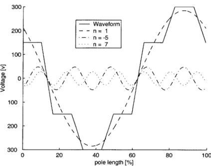
Motor-Compressor baseline turbomachinery design (from Shirley [51]). . . . . 49 2-6 Principle of operation of the electrostatic-induction motor. . . . . 51 2-7 Stator potential, discretized by six electrodes. . . . . 53 2-8 Stator potential distribution at one moment in time, and its harmonic
de-com position . . . . 54 2-9 A measure of motor power as a function of the number of electrodes used
to discretize the waveform, for constant voltage breakdown limit between adjacent electrodes (sinusoidal excitation). . . . . 58 2-10 A measure of motor power as a function of the number of electrodes used to
2-11 Stator potential distribution as a function of time, and its harmonic
decom-position. . . . . 60
2-12 Magnitude of the harmonics forming the stator potential when discretized with 6 electrodes. Arrows to the right and left indicate forward and backward traveling waves, respectively. . . . . 61
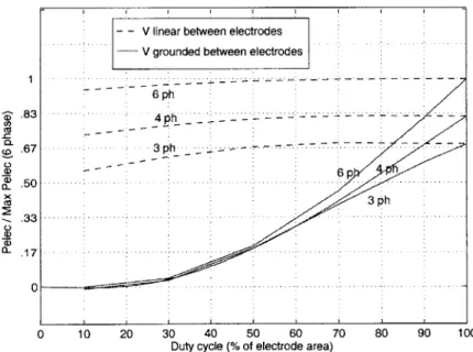
2-13 Predicted motor power as a function of duty-cycle, for 3, 4, or 6 electrodes per pole. . . . . 61
2-14 Schematic of viscous drag in the motor gap. . . . . 62
2-15 Section through the motor gap, taken in the circumferential direction. . . . 64
2-16 Various stator configurations for drag reduction . . . . 66
2-17 Schematic of hydrostatic thrust bearings (from Lin [29]). . . . . 70
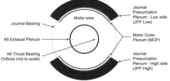
2-18 Aft plenum configuration. The motor (not shown here) occupies the area between the Motor Outer Plenum and the Aft Exhaust Plenum. . . . . 71
2-19 3D view of the secondary flow piping. . . . . 72
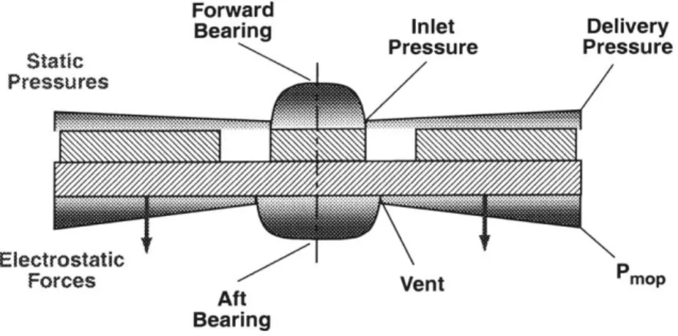
2-20 Schematic of axial forces acting on the rotor . . . . 73
2-21 Axial force balance on the rotor. . . . . 74
2-22 Hydrodynamic journal bearing forces. . . . . 76
2-23 Hydrostatic journal bearing operating principle. . . . . 77
2-24 Increase in journal bearing viscous drag as a function of eccentricity. .... 78
2-25 Predicted performance as a function of motor outer radius, for different rotor diameters, and constant tip speed of 400 m/s. . . . . 80
2-26 Predicted performance as a function of motor outer radius, for different rotor diameters, and constant tip speed of 200 m/s. . . . . 81
2-27 Predicted load and motor power curves as a function of tip speed . . . . 84
2-28 Alternate Motor-Compressor configurations. . . . . 85
2-29 Power flow illustrating the power consumption of a Motor-Compressor de-signed for the high pressure ratio application. . . . . 89
2-30 Schematic of conjugate heat transfer analysis for the Motor-Compressor con-figuration ... ... 90
3-1 Optical photograph of a MC-Bearing Rig die (from MCBR1 build). .... 97
3-3 Wafer #1: Forward foundation plate process flow . . . . 100
3-4 Wafer #2: Forward end plate process flow . . . . 100
3-5 Wafer #3: Rotor plate process flow . . . . 100
3-6 Wafer #4: Aft end plate process flow . . . . 101
3-7 Wafer #5: Aft foundation plate process flow . . . . 101
3-8 Final MC-Bearing Rig 5-wafer stack bond . . . . 101
3-9 Cross-section of the 5-wafer stack MC-Bearing Rig with schematic . . . . . 105
3-10 IR picture of the MC-Bearing Rig bonded 5-wafer stacks. . . . . 106
3-11 Illustration of backside pitting. . . . . 107
3-12 Illustration of the misalignment between wafers #3 and #4 of MCBRI. . . 108
3-13 Exploded view of the 5-wafer stack Motor-Compressor. . . . . 110
3-14 Rotor process flow for the Motor-Compressor. . . . . 113
3-15 Bottom side of MCI Rotor plate, after thin film processing and deep reactive ion etching. . . . . 114
3-16 Top side of MCI FEP after having been bonded to the rotor plate and the journal being etched. . . . . 114
3-17 TBOS stator process flow - part 1 . . . . 115
3-18 TBOS stator process flow - part 2 . . . . 116
3-19 Recessed Oxide Islands (ROI) stator process flow . . . . 117
3-20 Optical photograph of MCi stator die . . . . 118
3-21 Photograph of a delaminated Motor-Compressor die. To the left is the stator, and to the right, the back side of the rotor. An extra 4 mm impeller is also shown in between both halves of the die. . . . . 121
3-22 Photograph of the microrotors before bonding, showing the three types of motor-driven devices that where built: with turbine blades (Motor/Turbine), compressors blades (Motor/Compressor), or no blades (Motor/Disk) . . . . 122
3-23 Optical photograph of cleaved rotor wafer with photoresist, showing a region of possible undercut where the film is curling. . . . . 123
3-24 Quality of contact improvement after repeated cycles of compression (4000 mbar) at moderate temperature in a N2 low pressure ambient. Fringes are indicative of poorly contacted areas. . . . . 124
3-26 Wafer bow due to thin film stress as a function of film thickness . . . . 128
3-27 Cross-section of the journal bearing of Die #12 of MCBR1 . . . . 130
3-28 Schematic cross-section of wafers #2 and #3 showing the snap-off tab con-figurations. ... ... 132
3-29 SEM of a silicon snap-off tab before and after fracture, viewed through the center inlet port. . . . . 133
3-30 SEM of a silicon pillar before bonding. . . . . 134
4-1 Photograph of an MC-Bearing rig die, which has been casted in epoxy and diced through its center. . . . . 137
4-2 Photograph of the 4.2 mm diameter microturbine . . . . 138
4-3 Photograph of the MC-Bearing Rig and Motor-Compressor test set-up. . . . 140
4-4 Photographs of the package... 141
4-5 Schematic of the gas handling system. . . . . 143
4-6 Thrust bearing characterization at condition of maximum gap, shown for the dies tested from the first MC-Bearing rig build. . . . . 148
4-7 Aft thrust bearing flow rate as a function of FTB pressure. . . . . 149
4-8 Journal bearing static flow characterization . . . . 151
4-9 Power spectrum of the optical speed sensor signal . . . . 153
4-10 Spectrum as a function of time, showing the increased magnitude of oscilla-tions immediately before crash, relating both events. . . . . 154
4-11 Spectrum as a function of time, showing the effect of reducing the journal bearing pressure differential . . . . 155
4-12 Assembly of optical pictures of the crashed rotor after crashing at 510,000 RPM (first die of MCBR1 build) . . . . 156
4-13 Spectrum of the 510,000 RPM run, before and at crash . . . . 157
4-14 MC-Bearing rig speed evolution over time. Uncertainty in the tip speed measurement is 0.5% of the measured speed. Courtesy of Jacobson and W ong [24]. . . . . 158
4-15 Experimentally determined stability boundary for the Motor/Turbine device #1... ... ... 159
4-17 Turbine and bearing flow rates over the range of operating speeds for Device 2162
5-1 Schematic of one phase of the resonant power electronics. . . . . 167
5-2 Output waveforms from the set of phase shifted function generators (4 out of 6 phases shown). . . . . 168
5-3 Peak-to-peak voltage from the HP33120A function generators as a function of excitation frequency, showing a gradual drop off at high frequencies. . . . 168
5-4 Rotational speed as a function of excitation frequency - Op-Amp Drive . . . 170
5-5 Rotational speed as a function of excitation frequency - Op-Amp Drive . . . 171
5-6 Rotational speed as a function of voltage amplitude - Resonant drive . . . . 172
5-7 Rotational speed as a function of excitation frequency - Function Generator D rive . . . . 173
5-8 Rotational speed as a function of voltage amplitude -Function Generator drive 173 5-9 Comparison of predicted and measured rotational speed as a function of frequency . . . . 174
5-10 Viscous load curve and motor torque curves at different stator excitation frequencies . . . . 179
5-11 Stator electrode characterization . . . . 179
5-12 Torque balance in the Motor/Disk device . . . . 180
5-13 Raw signal from the fiber optic sensor during spindown. . . . . 182
5-14 Quasi-instantaneous speed as a function time during the spindown - die M/D # 1 . . . . 182
5-15 Viscous torque constant derived from the spindown data for die M/D #1 . 183 5-16 Viscous torque derived from the spindown data for die M/D #1 . . . . 184
A-1 Tangential velocity profiles as a function of Coriolis forces . . . . 204
A-2 Radial velocity profiles across the gap (mid-radius) for different pressure ra-tios (P 2/P1) . . . . 208
A-3 Tangential velocity at mid-radius across 3tm and 10pm gaps . . . . 208
A-4 Tangential velocity versus radius at mid-gap, for motor gaps of 3pm and 10pm209 A-5 Cross-section of the motor gap and the stator electrodes . . . . 210
A-6 Velocity vectors in a cross section of the motor gap for a nominal trench geom etry . . . . 216
A-7 Tangential velocity profiles from 3-D and 2-D calculations . . . . 216
A-8 Particle traces showing the vortex on the top region of the trench and the through-flow at the bottom of the trench. . . . . 217
A-9 Drag reduction coefficient as a function of duty-cycle (100% duty-cycle cor-responds to the smooth stator). . . . . 218
A-10 Drag reduction coefficient as a function of non-dimensional trench depth . . 218
A-11 Drag reduction coefficient as a function of non-dimensional sector length of an electrode+trench pair . . . . 219
C-1 Common process steps . . . . 226
C-2 Forward Foundation Plate - Wafer #1 . . . . 226
C-3 Forward End Plate - Wafer #2 . . . . 227
C-4 Rotor Plate -Wafer #3 . . . . 228
C-5 Aft End Plate (Stator) - Wafer #4 . . . . 229
C-6 Aft Foundation Plate - Wafer #5 . . . . 230
C-7 Device assembly and final processing . . . . 230
D-i Technical drawings of the MC-Bearing rig and Motor-Compressor package -Bottom plate . . . . 232
D-2 Technical drawings of the MC-Bearing rig and Motor-Compressor package -Spacer plate . . . . 233
D-3 Technical drawings of the MC-Bearing rig and Motor-Compressor package -Top plate . . . . 234
D-4 Technical drawings of the MC-Bearing rig and Motor-Compressor package -Electrical cover plate . . . . 235
LIST OF TABLES
2.1 Motor-Compressor baseline turbomachinery geometry, by S. Jacobson. . . 45
2.2 Measured compressor efficiency in the unshrouded macro-scale compressor test rig, from Shirley [51]. . . . . 46
2.3 Thrust Bearing Geometry for the Demo Motor-Compressor. . . . . 73
2.4 Design parameters for the Demo Motor-Compressor. . . . . 83
2.5 Summary of Motor-Compressor configurations: Overall Description . . . . . 86
2.6 Summary of Motor-Compressor configurations: Predicted Performance . . . 87
2.7 Summary of Motor-Compressor configurations: Design Detail . . . . 88
5.1 Summary of motor performance assessment . . . . 187
A.1 Motor gap parameters for the nominal motor-compressor configuration. . . 200
A.2 Viscous drag on the disk from 2-D axisymmetric computations and the Cou-ette flow approximation (Eqn A.3). . . . . 207
NOMENCLATURE
Roman
C capacitance (pF)
C, specific heat at constant pressure (J/kg K)
dc electrode duty-cycle, ratio of electrode area to total area
f
force per unit area, Pa (force per unit radius in App. A)k wave number, such that wavelength = 27r/k
g motor gap (m)
h blade height (m) ht trench height (m)
J rotor inertia
Kv viscous torque constant: Tic= K, Q (pNm
/
rad/s)1 characteristic length scale (m)
L inductance (pH)
rh mass flow (kg/s)
m number of poles
n harmonic number
p number of electrodes per pole
Pcomp power consumed by the compressor(W)
Pelec mechanical power delivered by the motor (W) Pir inter-row pressure (psi)
AP axial pressure differential across the journal bearing gap (psi) Pt total pressure (Pa)
r radius (m) R resistance () Ri inner radius (m) Ro outer radius (m) S Slip, Eqn 2.13 t time (s)
Telec torque of electrostatic origin (pNm) Tvisc viscous torque (pNm)
Tt total temperature (K)
U tip speed = Qr2 (m/s)
V velocity (m/s)
|ZI amplitude of voltage (Volts)
We electrode width (m)
Wt trench width (m)
I'eisc viscous power dissipated (W)
Greek
a conductivity parameter, Eqn 2.13
3 gap parameter, Eqn 2.13
#3'
relative trailing edge flow angle A rotor insulator thickness e rotor eccentricityEo permittivity of free space eri permittivity of rotor insulator
7r total pressure ratio = Pt,2/Pt, p density (kg/m 3)
Q rotational speed (RPM or rad/s)
w electrical frequency (rad/s) on bearing natural frequency
C-rfs rotor film sheet conductivity 0-ri rotor insulator conductivity
O-eff effective rotor film conductivity, Eqn 2.13 P fluid viscosity
Subscripts
1 location at inlet of compressor (leading edge) 2 location at exit of compressor (trailing edge)
c compressor
jb
journal bearing m motor r radial component i inner radius o outer radius z axial component 0 tangential componentAcronyms
2D two-dimensional (z and 0) 3D three-dimensional (r, z and 0)CFD computational fluid dynamics
DAQ data acquisition
FEM finite element model
MCBR Motor-Compressor Bearing Rig
M/T motor-assisted turbine
M/C motor-driven compressor
MEMS micro-electromechanical systems
RPM revolutions per minute
SCCM standard cubic centimeters per minute
ATB aft thrust bearing
FTB forward thrust bearing
JPP journal pressurization plenum
MOP motor outer plenum
AEP aft end plate
AFP aft foundation plate
FEP forward end plate
FFP forward foundation plate
RP rotor plate
BOE buffered-oxide etch
CMP chemical-mechanical polishing
DRIE deep reactive ion etching
STS deep reactive ion etcher from Silicon Technology Systems Limited
TBOS thick buried oxide in silicon (Sec. 3.3.3)
CHAPTER
1
INTRODUCTION
A technology which has greatly impacted our society over the previous four decades, is undeniably semiconductor manufacturing for microelectronics. This fabrication technol-ogy for silicon-based materials has enabled the advent of computing and signal processing microchips, which have taken an important role in our lives. Computer chips, comprised of millions of electrical components, are mass produced and sold for tens and hundreds of dollars. The semiconductor microfabrication technology developed to create these com-pact integrated circuits has been a major factor in the widespread use of microprocessors, by enabling cost-effective mass production of reliable, compact, and powerful information processing systems.
Beyond building electrical components, this fabrication technology has been extended to in-tegrate mechanical elements. Micro-electromechanical systems, or MEMS, have been built which combine simple mechanical elements, such as membranes, springs, and gears with electronic circuitry on a compact chip. The single-crystal silicon substrate and thin films typically used in microelectronics become structural elements. In addition to controlling the motion of electrons, these microsystems physically interacts with the environment, moving molecules, heat, and light. The new world that micromachines can open has long been recognized [16]. In addition to creating new tools for the scientific field, multi-functional microsystems hold great commercial promise, since they can be manufactured with the similar mass-production and cost-efficient approach as microprocessors. It has been rec-ognized since the 1980's that this capability opens the road for new compact devices to be introduced for applications previously unimaginable, or only viable with larger, heavier,
and more expensive devices.
Although these possibilities have not yet been fully commercially exploited, some MEMS devices have successfully reached the market over the past decade, for specific applications. The main examples are ink jet printer heads, automotive pressure sensors, automotive airbag accelerometers, and data storage read/write heads. The market segment taken by these products was on the order of $1.7 Billion in 1996 and is expected to grow to over $5 Billion by 2003 [55]. New applications for MEMS technology are emerging, such as opti-cal switching, Radio Frequency (RF) devices for wireless communication, and microfluidic lab-on-a-chip devices. In the microfluidic area, biomedical, as well as chemical testing and processing applications for MEMS are growing [60], and microfabricated valves are com-mercially available from Redwood Microsystems [64] and Hewlett-Packard [6]. Figure 1-1 shows the estimated MEMS sales by technology area [55], predicting a large growth in the microfluidics and chemical testing and processing area.
1996 1997 1998 1999 2000
Year
2001 2002 2003
Figure 1-1: Estimate sales of MEMS products by technology area (Courtesy of System Planning Corporation [55])
The popularity of MEMS mostly stems from the potential cost advantage, and from the unprecedented functionality they can offer. Current MEMS devices are typically low
en-4000
3500
3000
~ Inertial Measurement
Microfluidics; Chemical Testing & Processing optical Pressure Measurement RF - Other ?A C 0 0 0 .2 2500 2000 1500 1000 500 0
ergy, low power devices, useful to sense or lightly actuate on the environment. However, single crystal silicon, a common starting material in microfabrication, offers great structural characteristics [42]. In particular, the high strength-to-density ratio makes it a promising candidate for high speed rotating machinery. It is therefore credible to imagine compact, high performance micromachines based on high speed rotating machinery for high power applications. These devices could integrate an electrical motor or generator, with turbo-machinery to convert energy between the fluidic, mechanical and electrical domains for applications requiring compact power components. A potential type of microfluidic MEMS therefore consists of energy converting microsystems, or Power MEMS [10].
The focus of this work has been to design, fabricate, and demonstrate a millimeter-scale compression system, driven by an integrated electric micromotor, using electrical power to deliver a pressurized gas. This motor-compressor device is envisioned for use in microfluidic systems, such as compact fuel cells for power generation, portable analytical instruments for air sampling, and micro-refrigeration for cooling of electronics, microprocessors, or people. The approach is to use microfabrication technologies from the semiconductor industry and MEMS fields to create the compact system. It therefore holds the promise to be reliably batch produced and available for tens of dollars per unit, bringing a capability usually reserved for high-end applications to a broader consumer market.
This chapter will first state the objectives of this work, followed by a review of previous work on related micro-electromechanical systems and compact compression systems. The development approach will then be presented, as well as the outline of the thesis, and the expected contributions.
1.1
Motivation and Objectives
As portable power generation and compact fluidic applications increase in popularity, the need for adequate components will rise. In particular, there will be a need for fluid pump-ing and compression systems for applications where size, weight, and cost are important parameters.
guide the design:
" pCompressor: Pressurization of portable fuel cells in the range of 50-100W
- Mass flow: 0.1 g/s (5000 sccm, 5 1/min, 0.2 CFM) of air
- Pressure ratio: 2:1 (1 atm, 15 psig, 410" H20, 101kPa) - Fluid poweri: 7.3 W
" pBlower: Air circulation through analytical instruments such as gas analyzing sys-tems
- Mass flow: up to 0.3 g/s (15000 sccm, 15 1/min, 0.6 CFM) of air
- Pressure ratio: 24" H20 (0.06 atm, 0.9 psig, 6 kPa) - Fluid power: 1.5 W
These devices could serve in many fluidic applications, either as part of thermodynamic cycles which require compression, or simply to provide air flow through a constrained circuit. For example, the pCompressor device could be used for compression in compact cooling or refrigeration systems for microprocessors, electronics, or people.
The technological approach chosen to create such a device is through MEMS technology, since:
* Single crystal silicon and recent fabrication techniques allow the level of performance in MEMS to be pushed to that of macro-systems;
* High-speed turbomachinery promises high power-density micro-devices;
* Thin film processing technology allows the on-chip integration of an electrical motor to drive the compressor;
* Microfabrication allows batch processing, promising mass production at reasonable costs.
Based on this motivation and objectives, the following goals were defined for this research:
'Fluid power noted is the ideal compression work for the prescribed mass flow and pressure ratio, for standard conditions.
" Explore the feasibility of a microfabricated turbomachinery-based compression sys-tem;
" Determine the physical and technological issues which guide the design of such a micro-scale system;
" Develop the microfabrication techniques and methodology which allow the fabrication and successful operation of high-speed and high-power micromachines, and;
" Demonstrate such a device
1.2
Review of previous work and related technologies
In order to put the objectives of this work in context, this section will review previous work on similar microsystems and related technology. First, typical compression systems will be summarized, followed by microfabricated and traditional fluid pumping systems and components.
1.2.1 Typical compression systems
Various approaches are used to increase the pressure of a gas in conventional scale appli-cations. Low mass flow approaches typically achieve high pressure ratios, and consist of constraining the gases in a closed reservoir and reducing the volume through a movable wall. The most common examples include reciprocating pistons and diaphragms. Rotary vanes operate on the same principle, but deliver a higher mass flow with a compromise on pressure ratio. Turbomachinery is a very high mass flow alternative, since the fluid does not come to a rest, i.e. high throughflow velocities are possible. The increase in pressure comes from the work done by imparting angular momentum to the flow, through the rotat-ing machine. High pressure ratio is achievable if the impeller is operated at high tangential velocities, or by serially repeating the process. Among these alternatives, turbomachinery offers the highest power density, and will be the method adopted herein.
1.2.2 MEMS compressors, motors, and bearings
A variety of microfabricated fluid pumping system have been developed for microfluidic applications. They have mostly been pumps, for liquids, as opposed to compressors, for gases. The most common type has been volume displacement diaphragm pumps, activated by electrostatic [52], piezoelectric [14, 28], electromagnetic [1], electrohydrodynamic [48], or electro-thermopneumatic [36] forces. The chamber is usually connected to a pair of active or passive valves, controlling the inflow and outflow from the chamber. Diffuser valves have also been demonstrated, with no moving parts [54, 40]. A number of such micropumps have been reported in the literature, with flow rates ranging from tens to thousands of pl/min. These configurations provide at least three orders of magnitude less flow rate than desired for the pCompressor and pBlower applications (which must be on the order of 5-15 1/min), precluding them for high power applications.
A variety of micromotors have also been demonstrated over the past decade. They mostly were variable-capacitance motors built by surface micromachining of thin polysilicon layers [15, 34]. As will be discussed further in Chapter 5, these micromotors are six to eight orders of magnitude less powerful than necessary for the desired Power MEMS applications, mostly due to the small active area and low speeds (up to 25,000 RPM).
The highest peripheral speed microrotor found in the literature is the 50 Pm diameter gear driven by a pair of orthogonal linear comb drive actuators [53]. It has reached up to 300,000 RPM, which is near 1 m/s tip speed2
Most of these devices have been supported by dry friction on a center pin and bushing. Gas film lubrication has also been investigated, mainly to lift the rotor from the substrate [23]. Other micro-devices use gas film lubrication to support sliding motion, such as data storage writing heads, and more recently, cantilevers for atomic force microscope tips [47].
Finally a few microfabricated turbomachines have also been demonstrated, such as the Micro-Turbo-Generator by Wiegele [61]. Operation was however limited to tip speeds of 3.5 m/s, which is significantly less than desired for power applications.
Overall, previous work shows that most types of components are realizable through
micro-2
fabrication, but not to the level of performance necessary for the envisioned Power MEMS applications. It therefore remains to be proven that high-power components can be designed and micromachined for high levels of performance.
Miniaturized components and compression systems fabricated using conventional processes will be reviewed next.
1.2.3 Other miniature compression systems and components
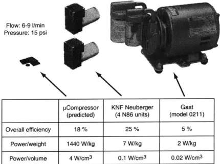
Other motor-driven compressors and blowers Various motor-driven compressors manufactured using conventional techniques are currently available on the market. Prices are typically in the few hundreds of dollars for high pressure ratio devices (2:1), such as the rotary vane compressor shown in Figure 1-2. We notice the large power density difference with the proposed MEMS pCompressor. Smaller diaphragm compressor are available for this pressure ratio, but offer less mass flow. A combination of 4 devices in parallel would be necessary to provide sufficient mass flow, as illustrated in Figure 1-2.
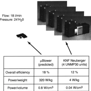
Similarly, a pair of diaphragm motor-driven compressors would be necessary for the pBlower specifications, as shown in Figure 1-3. The proposed MEMS pBlower still promises a significant power density advantage compared to its large scale counterpart. Typical fans used for cooling electronics are low speed and provide 1" H20, which is 20 times less than
necessary for this application.
The use of high power density microturbomachinery and drive technology in a batch fabri-cated MEMS device offers the possibility to miniaturize gas compression devices, and offer them at a relatively low cost.
Miniature turbomachinery, motors, and bearings Other applications have moti-vated the development of the main components of a motor-driven compressor. For example, air-driven dentist drills have prompted the development of high-speed miniature ball bear-ings, currently reaching up to 500,000 RPM at a 6.35 mm outer diameter (i.e. an outer rim speed of 170 m/s) [57]. Foil bearings have also been developed for high speed applications such as cryocoolers, with diameters as small as 1.65 mm (Creare [8]).
Flow: 6-9 1/min Pressure: 15 psi
pCompressor KNF Neuberger Gast (predicted) (4 N86 units) (model 0211) Overall efficiency 18 % 25 % 5 %
Power/weight 1440 W/kg 7 W/kg 2 W/kg Power/volume 4 W/cm3 0.1 W/cm3 0.02 W/cm3
Figure 1-2: Comparison of proposed pCompressor to commercially available motor-driven
com-pressors.
Both of these applications also integrate millimeter scale turbomachinery. Creare cryocooler impellers integrate three-dimensional, shrouded blades within a monolithic rotor, built by electro-discharge machining (EDM). The geometric flexibility of this fabrication approach comes however at the expense of low throughput, resulting in high unit costs.
Very small motors have also been developed, mostly for high frequency actuation in compact systems. For example, the smallest magnetic motor offered by Smoovy [49] is 3 mm in diameter, and provides a torque of 15 pNm at a speed of 60,000 RPM. Unfortunately, this corresponds to 0.1 W, which is approximately 50 times less power than necessary.
In order for the proposed MEMS Motor-Driven Compressor to be viable compared to these other available technologies, it should achieve the performance level of conventional com-pression systems, but with the cost advantage of MEMS batch fabrication. Its higher power density could also be considered as a competitive advantage, but to date, commercial MEMS success has mostly been characterized by the cost savings they provide.
Flow: 18 I/min Pressure: 24'H20
IBlower KNF Neuberger
(predicted) (4 UNMP30 units) Overall efficiency 18 % 12 %
Power/weight 320 W/kg 4 W/kg Power/volume 0.8 W/cm3 0.04 W/cm3
Figure 1-3: Comparison of proposed pBlower to commercially available low pressure
motor-driven compressors.
1.3
Development Approach
1.3.1
MIT Microengine Project
The Motor-Compressor development was part of a larger research project at MIT, aiming to demonstrate turbomachinery-based, energy conversion MEMS devices and technology,
i.e. Power MEMS [10, 13]. In addition to the Motor-Compressor, the other microengines
considered are: a centimeter-scale gas turbine engine for propulsion of Micro Air Vehicles (MAV), a gas turbine generator for portable electrical power generation, and a bi-propellant rocket engine with turbopumps [32, 46] for satellite attitude keeping or future micro-launch vehicles [18]. Many components and processing techniques are shared between de-vices, leveraging the microfabrication experience gained and the unique knowledge base developed for these devices.
The MIT Microengine project is structured along two axes: device-oriented development and disciplinary research. Disciplinary teams focus on the original research necessary in the fields of turbomachinery, bearings and rotordynamics, electromechanics, combustion, structures and materials, and microfabrication. Specific device development then crosses the necessary fields, guiding the disciplinary research efforts to satisfy device requirements.
Astronau-tics, Electrical Engineering and Computer Science, Material Science and Engineering, and Mechanical Engineering formed the collaborative research and development team.
Inter-disciplinary interaction was necessary to guide the research and determine the ade-quate balance between technological innovation, implementation risks, and timely achieve-ment of project milestones. For example, the Motor-Compressor developachieve-ment required a compromise between achievable system performance, high speed bearing operation, and manufacturability.
1.3.2 Motor-Compressor related work
The Motor-Compressor development path consisted of first establishing expected levels of component performance achievable with the given resources; then developing the neces-sary knowledge base, designing the components and the system, developing the fabrication techniques, building and demonstrating the components and the integrated system.
The disciplinary activities related to the Motor-Compressor project will be detailed in the relevant Chapters later in the thesis, but can be summarized as:
1. Electromechanics: analytical modeling and experimental verification of micro-motor design and power electronics [37, 38];
2. Bearings and Rotordynamics: modeling and experimental development of viable bear-ing designs and operatbear-ing protocols [41, 44, 50, 19];
3. Turbomachinery: computational and experimental development of viable compressor configurations [33, 51];
4. Microfabrication: unit process development, assessment of integration issues, and
device fabrication [29, 21].
The limited diagnostics available at the small scale has pushed the initial effort mostly toward analytical and numerical work, and scaled-up experimental testing. Macro test rigs of the gas-lubricated bearings [41] and compressor [51] provided extremely valuable demonstration of those components, which are characterized by non-conventional geometries and operating regimes.
Microfabricated devices also played a critical role in the Motor-Compressor development. The MicroBearing Rig was a development platform for the basic techniques to create a fusion bonded 5-stack of double-side etched silicon wafers [31, 30, 29]. The device was also a platform for microfabricated gas bearing development. Work by Lin [29] mostly investigated the hydrostatic bearing operation. This microbearing rig work guided the Demo Motor-Compressor design and testing, and established the process flow for the silicon structure of the Motor-Compressor.
Secondly, a tethered version of the micromotor was developed in parallel with the Demo Motor-Compressor, by Nagle [37, 38]. It is a 2-wafer device, consisting of the electrical stator and rotor of the electrostatic induction micromotor. The rotor is held by flexible tethers, which allow a measurable rotation of the rotor under electrostatic torque. The device aims to measure the electrostatic torque, validate the motor modeling, and concurrently develop fabrication processes for the thin film electric stator and rotor.
Furthermore, a turbine-driven generator is currently being developed based on the Motor-Compressor configuration [12]. High efficiency electrical components are being developed for this application, which will eventually be directly beneficial to a Motor-Compressor.
1.3.3 Device development plan
Top-level view The approach has been first to develop an experimental Demo Motor-Compressor, before pursuing the development of the pBlower and pCompressor devices, with the intent of limiting the level of risk. Component designs and fabrication processes were largely based on the valuable, although limited, experience gained by other researchers in the Microengine team.
The Demo Motor-Compressor development effort therefore focused on the unique and criti-cal aspects of this type of device, mainly the fabrication of a 5-stack device with integrated thin film components, and the high-speed journal bearing, micromotor, and integrated sys-tem operation.
This initial development phase aims to determine the validity of the proposed approach and identify the main challenges both at the component and system levels. The Demo
Motor-Compressor development will set the guidelines for the implementation of applica-tion specific devices. Although the system level designs of the plBlower and pCompressor configurations will be proposed, they have not been experimentally pursued.
Experimental device development Two types of devices were fabricated and tested: a second generation bearing rig and a set of motor-driven microrotors. The new bearing rig device was directly derived from the Demo Motor-Compressor design, and will be referred to as the MC-Bearing Rig. As described in Chapter 4, it was instrumental in developing the hydrostatic journal bearing and demonstrating high rotational speeds.
The motor-driven devices then go one step further from the all-silicon MC-Bearing Rig, and integrate the thin film micromotor in the 5-wafer stack to drive the rotor. In order to explore experimentally the operation of the electrostatic micromotor and demonstrate system level operation, three variants of motor-driven devices were built, which only differ in the blading:
1. Motor/Compressor: Disk with motor and compressor blades, intended for system-level demonstration;
2. Motor/Disk: Flat disk with motor but no blades, intended for viscous drag and mi-cromotor torque assessment;
3. Motor/Turbine: Disk with motor and turbine blades, intended for high speed bearing assessment and micromotor torque assist to achieve higher speeds.
Terminology The general configuration adopted here, of a planar motor driving a disk with compressor blades on the reverse side, will be referred to as a Motor- Compressor. The experimental motor-driven devices will be usually referred to as the Demo Motor-Compressor, since they share the same fabrication process flow and were built simulta-neously on the same wafer. Finally, the proposed configurations for the pressurization of fuel cells and aspiration for analytical instruments applications will be referred to as the pCompressor and pBlower respectively.
1.4
Scope of the Thesis
Figure 1-4 illustrates the topics covered and the various devices built as part of this work, mostly focusing on the demonstration of microscale components and systems. First, bearing rig work was pursued (Bearing Rig v.2, referred to herein as the MC-Bearing Rig) to demon-strate microscale hydrostatic journal bearing operation, and the operation of high-power density microturbomachinery. The set of motor-driven devices were then fabricated and tested, to study the operation of the micromotor, and that of the integrated microsystem.
Figure 1-4: Illustration of the experimental devices built and tested to demonstrate critical Power MEMS components and systems.
1.5
Thesis Outline
The work for this thesis extends along both main axes of the MIT Microengine Project: device oriented development and disciplinary research. Along one axis, original work has focused on system design, fabrication, and testing of the Motor-Compressor. Along the other axes, research in the disciplinary areas of microfabrication, electromechanics, and gas-lubricated bearings was undertaken when necessary for the successful operation and integration of the components in the Motor-Compressor. The thesis is structured to cover both axes, namely: the modeling and design, the microfabrication, and the experimental
development and demonstration of the components and the integrated system.
Chapter 2 provides an overview of the Motor-Compressor, and describes the component and system design. It will also present a summary of disciplinary work, by the author and by others, related to the Motor-Compressor development. The system design section will describe the main trade-offs in this unique design space and the suggested device configu-rations.
Chapter 3 will present the fabrication process, the results, and the experience gained in building the devices as part of this work. Major challenges in using deep reactive ion etching, wafer bonding, and thin film processing will be discussed, along with the techniques applied to successfully build the MEMS devices.
Chapter 4 will summarize the experimental development of the bearing system, which led to high speed operation. The focus will be on testing procedures and hydrostatic journal bearing operation.
The micromotor experimental development will then be described in Chapter 5. Charac-terization and testing of the set of 5-stack integrated micromotor-driven devices will be summarized, assessing the motor operation versus the expected performance. It also pro-vides a demonstration of the combined operation of the micromotor, the bearings, and microturbomachinery.
Finally, Chapter 6 summarizes the main aspects and contributions of the work presented herein, and suggests further disciplinary and device-oriented work.
CHAPTER
2
SYSTEM
AND
COMPONENT
DESIGN
This chapter will define the design basis for a microfabricated silicon motor-driven com-pressor. First, an overview of the baseline configuration will be presented, setting the stage for the following three sections, which will describe the function of each main component: turbomachinery, electromechanics, and bearings. The focus will mainly be on aspects which are important for system level design.
Disciplinary technology development for the components (especially the turbomachinery and bearing design) has mostly been the effort of other researchers. Important parts of their work will be included herein for completeness, and will be referenced accordingly. The author's contributions in micromotor fluidic and electromechanical modeling, as well as system-level design, constitutes the main substance of this chapter. The system design section uses a combination of component models to predict the device performance and efficiency, and explores the design space for this new type of device. Optimum configurations are suggested for the envisioned applications, based on the specific technology developed and on the unique limitations of silicon microfabrication. The design of the Demo Motor-Compressor and MC-Bearing Rig development devices will be presented, as the basis for the experimental work presented in the other chapters of the thesis.
2.1
Baseline System Overview
The motor-compressor is composed of the following components, illustrated in the schematic cross-section (Figure 2-1):
1. Radial impeller and diffuser 2. Journal and thrust bearings 3. Electrostatic induction motor
4. Fluid piping and electrical connections
Main air discharge Compressor diffuser impeller 'K7 Journal air bearing Main air inlet External electrical
Forward thrust leads
bearing
K00
Motor
Electric
Journal outer Aft Thrust Aft Induction
pressurization plenum Bearing exhaust Motor
Figure 2-1: Cross-section schematic of the motor-driven compressor.
After fabrication, the motor-compressor consists of one moving part, the rotor, enclosed in the static structure. The rotor is a low aspect ratio disk with the turbomachine rotor blades on the front side and the electric motor on the back side. The in-plane motion of the rotor disk is supported by a gas journal bearing on its periphery, and the axial motion is restrained by central thrust bearings on each side of the disk. The electrostatic induction motor applies torque on the rotor by inducing charges on the back side of the disk, across an air gap, and dragging them tangentially. This applied torque spins the disk and the impeller blades on the front side. The pressure rise created by the compressor entrains air
from the inlet to the discharge, feeding an external system such as a fuel cell or an air analysis system.
The main system design challenge consists of defining the components of a system delivering the prescribed fluid power, within the constraints of state-of-the-art microfabrication and reasonable new technology development.
Before discussing the system design, the design of the turbomachinery, the electrostatic-induction motor, and the gas bearings will be summarized.
2.2
Turbomachinery
The approach in achieving compression is based on high-speed turbomachinery. The de-sign space differs from conventional turbomachinery due to the small-scale and the limited fabrication flexibility, as will be discussed in the following sections.
2.2.1 Turbomachinery scaling
Since thermodynamic cycles do not change with size, the pressure rise required from a micro-compressor is similar to that required from a conventional scale machine, when the application is miniaturized. Since fluid power delivered can be approximated by the product of pressure rise and volume flow, it scales with the mass flow. Furthermore, if high through-flow velocities are maintained, the mass through-flow, and fluid power will scale with the through-through-flow area 12, where I is a characteristic dimension of the flow path. This suggests that the power density of a miniature turbomachine should not degrade, but increase inversely with the scale: Power rh APt/p Volume 13 V12 Ap 1 c - -* for constant V, AP
This scaling is only valid if the same level of pressure rise is achievable in a microturbo-machine as in its large-scale counterpart. Since the pressure rise is proportional to level of turning across the blade row, high tangential velocities (tip speed) and high through-flow velocities are necessary (i.e. similar velocity triangles). To first order, if the spacing between blades is reduced with the chord (as shown in Figure 2-2), the diffusion within the blade passage and the turning achievable will remain constant (for constant velocities). This implies that similar power per unit area can be expected for high performance micro and macro scale turbomachines. The reduction in scale however delivers this power per unit area over a shorter length. The scaling law described above can therefore be interpreted
simply in terms of shorter turbomachinery, for constant power per unit through-flow area: Power Power 1
Volume Area chord
1
oc h -+ for constant power per unit area
chord
j77"z
V\ U
U V, O /0000""0-K>
ChordFigure 2-2: Scaled blade row, conserving the non-dimensional geometry.
It is important to note that the necessity for high tip speed drives the requirement for other components in the systems (the bearings and the motor), as well as the strength requirements of the rotating structure.
The power density benefit of micro-turbomachinery must be traded-off with efficiency. The small-scales, for similar flow properties and velocities, are characterized by higher viscous losses, represented by lower Reynolds Numbers. Figure 2-3 quantifies this effect by plotting the loss coefficient as a function of scale (i.e. Reynolds Number) for a centrifugal compres-sor. The numerical study was done by Jacobson [25] using the CFD code MISES [9] on the baseline Motor-Compressor geometry. The figure suggests a practical limit to turbomachin-ery miniaturization, beyond which the component inefficiency will overwhelm the benefit of higher power density, for a specific application.
In addition to low Reynolds number operation, the geometric constraints imposed by mi-crofabrication strongly impact the turbomachinery design. This constrained design space led to a non-standard blading design, as described next.
![Figure 2-3: Loss coefficient as a function of Reynolds Number, representing the effect of higher viscous losses at small scale (by Jacobson [25]).](https://thumb-eu.123doks.com/thumbv2/123doknet/14732584.573361/44.918.252.689.120.444/figure-coefficient-function-reynolds-number-representing-viscous-jacobson.webp)
![Figure 2-4: 2D and 3D view of the baseline compressor, designed by S. Jacobson [24].](https://thumb-eu.123doks.com/thumbv2/123doknet/14732584.573361/45.918.131.783.120.454/figure-d-d-view-baseline-compressor-designed-jacobson.webp)