Publisher’s version / Version de l'éditeur:
Journal of Geotechnical Engineering, 119, September 9, pp. 1431-1447,
1993-09-01
READ THESE TERMS AND CONDITIONS CAREFULLY BEFORE USING THIS WEBSITE. https://nrc-publications.canada.ca/eng/copyright
Vous avez des questions? Nous pouvons vous aider. Pour communiquer directement avec un auteur, consultez la première page de la revue dans laquelle son article a été publié afin de trouver ses coordonnées. Si vous n’arrivez pas à les repérer, communiquez avec nous à [email protected].
Questions? Contact the NRC Publications Archive team at
[email protected]. If you wish to email the authors directly, please see the first page of the publication for their contact information.
NRC Publications Archive
Archives des publications du CNRC
This publication could be one of several versions: author’s original, accepted manuscript or the publisher’s version. / La version de cette publication peut être l’une des suivantes : la version prépublication de l’auteur, la version acceptée du manuscrit ou la version de l’éditeur.
Access and use of this website and the material on it are subject to the Terms and Conditions set forth at
Pipelines and laterally loaded piles in an elasto-plastic medium
Rajani, B. B.; Morgenstern, N. R.
https://publications-cnrc.canada.ca/fra/droits
L’accès à ce site Web et l’utilisation de son contenu sont assujettis aux conditions présentées dans le site
LISEZ CES CONDITIONS ATTENTIVEMENT AVANT D’UTILISER CE SITE WEB.
NRC Publications Record / Notice d'Archives des publications de CNRC:
https://nrc-publications.canada.ca/eng/view/object/?id=f2f2345a-09e6-47f8-b844-46c6931370f3 https://publications-cnrc.canada.ca/fra/voir/objet/?id=f2f2345a-09e6-47f8-b844-46c6931370f3Pipe line s a nd la t e ra lly loa de d pile s in a n e la st o-pla st ic m e dium
N R C C - 4 0 6 0 2
R a j a n i , B . B . ; M o r g e n s t e r n , N . R .
S e p t e m b e r 1 9 9 3
A version of this document is published in / Une version de ce document se trouve dans:
Journal of Geotechnical Engineering,
119, (9), September, pp. 1431-1447,
September, 1, 1993
http://www.nrc-cnrc.gc.ca/irc
The material in this document is covered by the provisions of the Copyright Act, by Canadian laws, policies, regulations and international agreements. Such provisions serve to identify the information source and, in specific instances, to prohibit reproduction of materials without written permission. For more information visit http://laws.justice.gc.ca/en/showtdm/cs/C-42
Les renseignements dans ce document sont protégés par la Loi sur le droit d'auteur, par les lois, les politiques et les règlements du Canada et des accords internationaux. Ces dispositions permettent d'identifier la source de l'information et, dans certains cas, d'interdire la copie de documents sans permission écrite. Pour obtenir de plus amples renseignements : http://lois.justice.gc.ca/fr/showtdm/cs/C-42
PIPELINES AND LATERALLY LOADED PILES IN ELASTOPLASTIC MEDIUM
By B. RajanP and N. Morgenstern,2 Member, ASCE
ABSTRACT: The uplift behavior of a shallow pipeline embedded in an elastoplastic medium is examined. An analytical solution for a beam on elastoplastic foundation
is developed and a characteristic nondimensional load-displacement and stress-displacement relationship are presented. An approximate three-dimensional (3D)
solution is proposed that accounts for embedment and breakaway condition behind the pipeline making use of the load-displacement curves developed for rigid anchors by Rowe and Davis in 1982. A comparison of these results with those obtained by
30 finite-element analysis indicates that the simplified solution of a beam on elas· toplastic foundation is a practical alternative for analyzing the uplift behavior of shallow pipelines. The approximate solution is also used to compare the behavior of a laterally loaded pile for which no separation or separation between the sur-rounding soil and the back of the pile is permitted as the load is monotonically increased. The results are presented in the form of nondimensional charts that permit hand calculations and rapid verification of structural design of the pipeline and piles.
INTRODUCTION
Over the past two decades several proposals have been put forward for the construction of a gas pipeline from the Arctic to the southern populated areas (ASCE: "An overview" 1978). These pipelines must be buried because of regulatory control. One method that has been suggested is to transport gas at below freezing temperatures and thus avoid the thawing of permafrost soils. However, this would lead to freezing of previously unfrozen soils in zones of shallow and discontinuous permafrost. It is expected that a frozen annulus would develop in a frost-susceptible soil around the proposed gas pipeline, leading to significant water migration to the freezing front and the formation of ice lenses. Consequently, frost heave would be induced, thus forcing the pipeline to move upward. The pipeline could undergo substantial straining, leading to wrinkling buckles, especially when the pipeline tra-verses a transition zone between two soils with different frost susceptibilities or between unfrozen and already frozen soils. Ever since the chilled-gas pipeline concept was proposed, the effect of frost heave on pipelines has been identified as an important issue that should be addressed.
However, it is appropriate to note that similar interactions are present in a variety of situations such as that of a laterally loaded pile embedded in a stiff soil or permafrost, a pipeline subjected to fault movement, a pipeline subjected to landslide movement and so on. The significant dif-ferences between that of a pipeline and pile would be the imposed loads (prescribed displacements versus imposed loads), and the near-surface ef-fects would have to be accounted for with the shallow burial of the pipeline.
'Assoc. Res. Ofcr., Nat. Res. Council, Inst. for Res. in Constr., Ottawa, Ontario,
Canada K1A OR6.
2Univ. Prof., Dept. of Civ. Engrg., Univ. of Alberta, Edmonton, Alberta, Canada T6G2G7.
Note. Discussion open until February 1, 1994. To extend the closing date one month, a written request must be filed with the ASCE Manager of Journals. The manuscript for this paper was submitted for review and possible publication on May 20, 1991. This paper is part of the Jourmd of Geotechnical Engineering, Vol. 119,
No.9, September, 1993. ©ASCE, ISSN 0733-9410/93/0009-1431/$1.00 + $.15 per page. Paper No. 2014.
1431
lrf11
1''.' ' ''
.,.,
-However, creeping behavior in the classical sense refers to the response of any structure with time subjected to a constant load. In this analysis we therefore assume that frost heave takes place sufficiently slowly so that the
load increment between a specific time interval is nearly constant.
To understand soil-pipeline interaction, especially in the context of a
frozen surrounding medium, a number of aspects need to be considered.
These include: (1) The mechanics of frost susceptibility and frost heave, which essentially constitutes the loading process; (2) the modeling of me-chanical properties of frozen ground; and (3) the modeling of meme-chanical response of the pipeline. Though each of these aspects has been well studied individually, there is a lack of proper understanding of the interaction be-tween frozen soil and pipelines.
Frost susceptibility and frost heave have become reasonably well under-stood and have been studied (Penner and Veda 1978; Nixon et al. 1981; Konrad and Morgenstern 1983, 1984). These aspects are not discussed fur-ther here. Although the prediction of frost heave is not an easy task, it can be estimated reasonably with currently available experience and knowledge. The mechanical behavior of frozen soil has been studied by Sayles (1973), Sayles and Haines (1974), Sego and Morgenstern (1983), and others. It is now widely accepted that ice-rich frozen soil behaves like a creeping ma-terial. The most likely circumstances of a pipeline subjected to frost heave would be associated with primary and secondary creep phases of straining. The classical studies of Glen (1955) indicate that the flow law of ice-rich soils is that of the Norton type. The Norton creep relationship rewritten in the generalized form as proposed by Ladanyi (1972) is
(;J
or i;= Ba"
... (1)where E =axial strain rate; rr = axial stress; Eo and <T0 =proof strain rates and proof stress; B and n = creeping constants. Typically, n is about 3 (Morgenstern et al. 1980) for ice at low stresses and icy silts (McRoberts et al. 1978). In search for a dependence of nand Bon temperature, Mor-genstern et al. (1980) found from analyses of available creep data that ice
behaves more as a linearly viscous material at temperatures close to 0°C.
The constant B is found to be temperature and material dependent. Sego and Morgenstern (1983, 1985) studied the behavior of laboratory prepared polycrystalline ice and have indeed confirmed the applicability of the Nor-ton-type power law. In the past, considerable attention has also been paid to the behavior of polycrystalline ice, primarily for glaciology studies and laboratory studies related to geotechnical problems. Polycrystalline ice is a
good material to work with since control can be exercised over its
charac-teristics in the laboratory. Sego and Morgenstern (1985) studied the inden· tation problem in polycrystalline ice both experimentally and numerically using finite elements, and they were able to simulate comparable behavior. As just seen, the analysis of the interaction of frost heave with a pipeline is a complex problem in which many processes need to be examined for a proper understanding of the complete system. In the present work, we propose to decouple the frost-heave process in the frost-susceptible soil from the pipeline in the non-frost-susceptible soil. This implies that we should apply an attenuated frost-heave rate at the transition zone of the two types of media rather than the free-field frost-heave rate (that which is usually
measured in the laboratory). Presently, we assume that it can be readily approximated.
Previous attempts at solving this problem and specially that related to pipelines have been made by Nixon et al. (1983) and Selvadurai (1988). Nixon et al. (1983) simplified the problem to that of plane-strain conditions and applied the free-field frost heave over a predetermined section of the frost-susceptible soil and studied its attenuation specifically at the interface of the frost and non-frost-susceptible soils. However, the pipeline was con-sidered as a passive component of the whole system and hence its interaction effects were not studied. Using the thermoelastic analogy, Selvadurai (1988) analyzed the elastic behavior of an embedded pipeline at shallow depth. As indicated previously, frozen soil hardly behaves as an elastic material and hence the application of this analysis is limited.
The motivation for studying the behavior of a pipeline (beam) on elas-toplastic foundation is that for ice, n is found to be within the range of 3 to 4 and this is sufficiently large so as to be analogous to a rigid-plastic material (n-> oo) (Panter et al. 1983; Boyle and Spence 1983). Of course, the material behavior is linearly viscous when n = 1 in a Norton-type relationship. It is this former aspect that is of interest because it permits us to establish bounds on the true behavior. In this paper we present the solution for a beam on elastoplastic foundation, and an approximate three-dimensional (30) solution is also proposed. These results are then compared with 3D finite-element analyses; they indeed confirm the validity of the simplified 30 solution.
Since the development of the solution is of a general nature in that it can be readily adapted to the analysis of a pipeline or a pile, we shall refer to
either structure as a beam and the surrounding medium as the foundation.
Yamada (1988) reported an analysis along the same lines, in which the beam was of finite length and applied to the problem of bonded-joint cracking.
BEAM EMBEDDED IN ELASTOPLASTIC MEDIUM
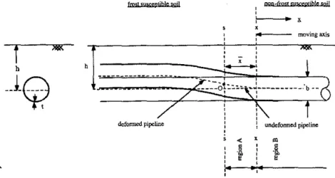
For the present analysis we assume that the beam is buried in a homo-geneous and isotropic elastoplastic medium and that when subjected to uplift the beam exhibits a double curvature (Fig. 1). We recognize that, in fact, for shallow pipelines this may not be totally valid. The elastoplastic behavior of the medium is represented by a bilinear force-displacement relation. If the elastic subgrade modulus is represented by k, then the foundation stiffness k; is given by k; = bk, where b = beam width (pile or pipeline diameter). Typically, the maximum force/unit length (F,) resistance avail-able for sand (Trautmann et al. 1985) and for clay corresponding to the undrained state can be expressed, respectively, by
F, = 'fbzN, ... (2a) F,
=
N,bs.=
N,bc=
N,brry ... (2b) where z = depth of embedment; and N, = dimensionless factor that de-pends on material properties of the sand; "Y=
medium unit weight; s.=
undrained strength ( = c, the cohesion for a purely cohesive material that follows the Mohr-Coulomb failure criterion); and N, = a factor analogous to the bearing capacity factor (which is discussed in detail later). In the case of an elastoplastic medium, the undrained shear strength could be replaced by the yield strength rry. Also, the limiting elastic displacement, U., isexpressed as
F:/ k;.
'.1
I1
l
i1
II
noq4rmtt ff!!fl(;tmtjbJe liQil
! moving axis
' '
defonned pipeline : l undefonned pipeline ' < '
Mセ@
-FIG. 1. Vertical Uplift of Pipeline due to Frost Heave
A consequence of the double curvature mentioned earlier is that the transition point 0 (Fig. 1) is a point of inflexion where the bending moment is zero. If, on the other hand, we choose to look at the problem as that of a pile subjected to lateral load P, then the equivalent problem of a pipeline subjected to frost heave would be given by a prescribed displacement of w"
=
P1312k;, where13
=
セォ[iTeャ@ where E and I are beam elastic modulus and moment of inertia respectively;13
is the so-called characteristic length. We also note that the resulting problem is statically indeterminate. We shall formulate the problem in terms of the load, P, but the corresponding pre-scribed end-displacement solution can be obtained as indicated earlier. We • recognize that the frost-heave problem is one of imposed displacement rather than load. However, creeping behavior in the classical sense refers to the response of any structure with time subjected to a constant load. In this analysis we therefore assume that frost heave takes place sufficiently slowly so that the load increment between a specific time interval is nearly constant. A sequence of events as a result of the interaction between the beam and the surrounding foundation takes place as the load is monoton-ically increased; these can be described as follows:• On initial application of the end load, P (0 :5 P,;;; P,), the embedded
beam as well as the soil behave elastically; P, = load level beyond which inelastic strains are induced in surrounding soil.
• As the load P is increased to a load level P, :5 P :s; P2 , ultimate
passive resistance will be developed in part of the surrounding soil medium but the pipe will remain elastic; P2 = load level beyond
which inelastic strains are induced in the soil as well as in the pipe-line. Referring to Fig. 1, we define an axis x-x that distinguishes two regions: region A, where the medium is in an elastoplastic state, and region B, where the medium is still elastic. The position of the axis x-x will shift from initial position s-s, where it is initially coin-cident with the edge where the load or prescribed displacement is
applied. The shift from the far edge to the axis x·x is denoted by i at any particular loading stage.
• As the load Pis further increased to, say, P2 :5 P :5 P3 , the distance
i increases when a plastic hinge begins to develop in the beam or wrinkles develop in the beam depending on the structural charac· teristics of the beam; P3 is the load level beyond which the pipeline
section is fully plastic.
Our object here is to trace this load-resistance behavior for the first two events.
Stage 0 :5 P s P1 and w s U,
As noted earlier, for a load 0 :5 P,.;; P1 and as long as the displacement
w does not exceed the limiting elastic displacement of the soil, i.e. w :5 U,
the solution for a beam on elastic foundation is perfectly valid and the corresponding differential equation, boundary conditions, and solution (He-tenyi 1968) are
d'w
El dx'
+
k;w=
0 ... (3) and at x = 0 we have -M = Elw" = 0 and -S = Elw"' = P. The displacement is given byRpセ@
w =
k'
e-"' cos セク@ ... (4)'
for 0 s x :::; oo.
Stage pl $ p :s:; Pz and w セ@ Uz, Epipeline :5 Ey
As soon as the beam displaces sufficiently so as to exceed the elastic displacement limit U, then an ultimate passive resistance offered by the surrounding soil will be acting on that portion of the beam while the rest of the beam-foundation is still elastic. It is also required that no plastic strains be induced in the pipeline during this loading stage, i.e., EpipeHne :::;
•r·
The equilibrium equations for the two regions described earlier are as follows. Region A -xsx:s;O Region B Eld'wn k' 0 d;c4+
.rWB = ... (6)where i has been defined earlier. The corresponding solution for the dif-ferential equations are
F x4 C
1x3 C2x2 C
w A = - 24EI
+
-6-+
-2-+
,x+
c,
... (7)w8
=
e -O>[C5 cos セ@+
C6 sin セク}@ ... (8)'i/
)
;
I,
IT
where C,, i = 1, 2, ... , 6 are constants. In the foregoing equations we have seven unknowns-six C, constants and
x.
The necessary boundaryconditions are at x = - i for moment
-M = Elw'' = 0 ... (9a) and shear
-s
= Elw'" = P ... (9b)for displacement and slope compatibility; and for moment and shear equi-librium at x
=
0, we have the following.Displacement セ]セᄋᄋᄋᄋᄋᄋᄋᄋᄋᄋᄋᄋᄋᄋᄋᄋᄋᄋᄋᄋᄋᄋᄋᄋᄋᄋᄋᄋᄋᄋᄋᄋᄋᄋᄋᄋᄋᄋᄋᄋᄋᄋᄋᄋᄋᄋᄋᄋᄋᄋセ@ for slope キセ@ = キセ@ ... (9d) for moment キセ@ = キGセ@ ... (9e) for shear キセ]キセ@ ···M The last boundary condition is obtained from the fact that at x = 0 the rate of variation of shear is equal to the ultimate soil passive resistance/unit length; i.e.
d4
wA d4wa
EI dx'
=
EI dx'=
-F> ... (9g) The seven boundary conditions given in (9) permit the evaluation of theseven unknown constants. They are P- xF C, = EI ' ... (lOa) ... (lOb) 13( -2i132P
+
i 213'F, - F,) C3 = k' ... (lOc)c,
=c,
C 5=
k' F,'
' ... (lOd) ... (lOe)-c,
c,
= 213' ... (10!)xl3
= 2PI3 - 1 ... (lOg) F, 1436It is important to note that i is always positive in accordance with particular manner that we have established (5) and applied the corresponding bound-ary conditions in (9a). We note from the last equation of set (10) that the region A increases (i.e., i increases) asP increases and that i is zero until at least
pRセ@
...HQQセ@
セ]セ@
...PQセ@
Eq. (11) also ensures that load level P always results in a positive value of i. The displacement at the point of application of the load can be evaluated as a function of the applied load to determine what is commonly termed the characteristic curve. Interestingly enough, the expression so obtained can be conveniently expressed in nondimensional form, i.e.W =
Nc
G
+セ@セ」@
+セ@ セ[I@
· • • • • · ... · • .... · ... · · ... , , ... , , (12)where
w
= wk;lbc; andP
= Pfl/bc. In the design of a pipeline or a pile, we would normally be interested in the maximum bending moment or stress. The maximum bending moment in the beam depends on the load level and needs to be identified in two stages, as identified earlier. During the first stage, i.e. 0,; P,; P1 , the load level is such that both the soil and pipelineare elastic. The maximum moment is easily identified by usual procedures and is as expressed in (13a). During the second stage of loading, i.e. P1 , ;
P .s P2 , the maximum curvature can develop on either side of the moving
axis x-x since different fu!,lction,s 、・ウセイゥ「・@ the displacement pattern as in-dicated in (7) and (8). If P1 s P ,; ZP 1 then the maximum moment Y」」オイセ@
to t!Je left of axis x-x and is given by (13d). On the other hand, if 2P1 , ; P
s P,, the maximum moment is to the right of axis x-x and is given by (13b). The three specific load levels identified earlier can be expressed in
nondi-mensional form Mfl -p - e -lli · ウュクキ・イ・セM fl' h "'' - :': d P < P (13 )
T
。ョ@ - 1 • • . • • • • • • • • • . • • • . • a Mfl e-•'Nc
[ .
A,-
= ----
ウュセ@+
P ZP(z
セBM
1) cos flx] ... (13b) wheretan
fli
= (N"p
P) and 2P1 s P ,; P3 • • • • • • • • • . . • • • • • . • • • • • . • (13c)Mfl 3
P
ZN"
p = Z
Nc
+ 4 -p " " ' " ' " " " ' " .. ' " " " .. " " .. "
'(13d) where flx = 1 -セ@
andP
1 sP
"'
2P1 c (13e) 1437Nonetheless, point .f of maximum moment increases as the load is mono-tonically increased.
APPROXIMATE 30 SOLUTION FOR BURIED BEAM
Rowe and Davis (1982) examined the undrained behavior for vertical uplift as well as horizontal movement of a rigid thin anchor in a saturated clay. Their study was limited to two-dimensional (2D) plane-strain condi-tions, and the researchers considered the influences of anchor embedment, layer depth, overburden pressure, breakaway condition or separation, and other aspects on load-displacement behavior. The numerical solutions were obtained using finite-element techniques assuming that the soil was purely cohesive and behaved according to the Mohr-Coulomb criterion. Additional assumptions made in the study can be found in Rowe and Davis (1982). In the case of a cohesive soil and for the specific case of undrained loading response, the cohesion is equal to the undrained shear strength. Conse-quently, for the analysis of the uplift behavior ofthe pipeline and the laterally loaded pile, the maximum resistance F, can be expressed as indicated in (2b). In the present analysis, we propose to use findings of Rowe and Davis (1982) related to vertical uplift of anchors to study the uplift behavior of pipelines and those related to horizontal movement of anchors to study lateral pile behavior. Essentially we make use of the load-displacement curves (commonly referred to as characteristic curves) for vertical uplift of anchors (Figs. 2 and 3) and horizontal movement of anchors where full bonding or immediate breakaway is allowed for between the anchor and soil. The specific solutions were obtained for an anchor lying on the surface, i.e. hlb
=
0 and for an anchor deeply buried, i.e. hlb=
oo, These provide lower- and upper-bound solutions for the uplift capacity as expressed in12 8 4
.. ...-
セNᄋ]@ セB@0.48 $ =0 y=O fully bonded upper bound, hlb = ooAnchor displacement, w E/bc
FIG. 2. Load-Displacement Curves for Rigid Anchors, No Separation [after Rowe and Davis (1982)]
12,---.
8 4-v. =0.48 $=0 Y=O fully bonded upper bound, hlb = oo collapse load, h/b = 1I
セセ@ .. セMMMMMMMMMMMMMMMMMM 0 0 5 10 15 20Anchor displacement, w E/hc
FIG. 3. Load-Displacement Curves for Rigid Anchors, with Separation [after Rowe and Davis (1982)]
(2b ). For a vertical anshor and embedment ratio of hJb = 0 we have the Prandtl solution, and N, is 5.14. The corresponding N, value for h/b
= "'
is 11.42. Rowe and Davis (1982) found in their analyses that it was partic-ularly difficult to define failure. They proposed that failure be considered to have been reached when the displacement is a selected multiple of that which would have been reached had the conditions remained entirely plastic. l!' fact, they showed through their analysis that for hlb > 3, the value of N, (=
11.42) is essentially constant for a vertical anchor and its variation from 5.14 for hlb=
0 is practically linear till hlb=
3. Consequently, we propose to use the equivalent bilinear representations of the vertical and horizontal load-displacement curves for anchors to represent the response of the soil in order to obtain an approximate 3D characteristic curve for the uplift behavior of a buried beam and the response of a laterally loaded pile. As we shall see, this also permits us to obtain an economical solution for the beam embedded in a medium in which separation is permitted to take place between the beam and the surrounding soil.The characteristic curves for uplift resistance of a buried beam obtained by making use of the aforementioned load-displacement curves are shown in Figs. 4 and 5. The effect of separation may be of considerable importance for the lateral behavior of a pile, although it is believed that the
pipeline-frozen soil interface could sustain adhesion and thus limit if not avoid separation. The loads and displacements obtained in Figs. 4 and 5 are within the range of small-displacement formulation.
FINITE-ELEMENT ANALYSIS
The following points should be kept in mind in order to compare the finite-element solutions with the proposed approximate solutions using
Ioad-1439
'
f
ri
セ@
.. •.·· .•.:
,, rrl1.
1
ji;
i
l
セ@20 V,=0.35
。ョイオ|セM
セ@ =0 r=o hlb = 00 15 fully bonded"
.e
analytical fit with N. = 6.35=
...
J___
-g
10 -.sa '--=-
-=--"'
.li
'
⦅LNLNMセ@ -hib=O '/ / .
5/;;
finite element, h/b = 1.55End displacement, k: w
/be
FIG. 4. Nondlmenslonal Load-Displacement Curves lor Beam on Elastoplastlc Foundation, Analytical versus 3D Finite Elements
1 . 0 0 ,
-0.75 0.50 0.25 ! v, = 0.35 セ@ =0 r=o fully bonded analytical -セM
---- _ -hlb=oo--/
- -=--
-=----/ /_::-/ /_::-/ - <""-/ • ...-... ana1ytical fit with Nc = 6.35
,/,\'
'I-'
finite element, hlb = 1.55
End displacement, k; w
fbc
-
-FIG. 5. Nondlmenslonal Maximum Moment-Displacement Curves for Beam on Elastoplastic Foundation, Analytical versus 3D Finite Elements
an<:bor representation sepa<ation at back of pile
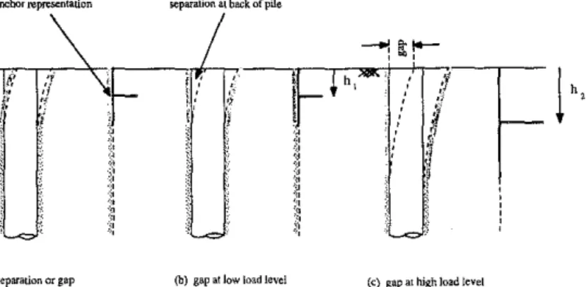
(a) no separation or gap (b) gap at low load level (c) gap at high load level
FIG. 6. Lateral Loading of Pile with Separation at Back of Pile
displacement characteristics for vertical and horizontal anchors developed by Rowe and Davis (1982).
Finite-element solutions for anchors as developed by Rowe and Davis (1982) represent a plane-strain condition. Meanwhile, the embedded beam (pipeline or pile) in a surrounding medium (frozen soil or soil) is between a plane-stress and a plane-strain condition.
The load-displacement curves for vertical anchors given by Rowe and Davis (1982) can be directly used for the study of uplift resistance of pipe-lines. The corresponding use of the load-displacement curves for horizontal anchors to comprehend the behavior of a laterally loaded pile is not so obvious. For the latter case, the uppermost part of the pile can be envisaged as an anchor that steadily grows in depth (Fig. 6), as the load is increased. A relation between the elastic modulus of the continuum and the so-called foundation subgrade modulus used for the simplified problem as proposed by Vesic (1961) is given by
k;
=セMセUセセ@
IJ¥/- • • • .. • • • .. • •. • • •. • • .. • • .. • •. • • • •. • • • .. • •
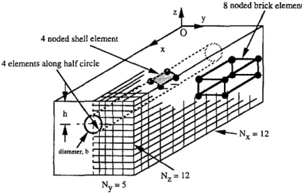
(14) Uplift Resistance of Buried PipelineTo validate the approximate 3D solution for a beam embedded at finite depth, a finite-element model for the embedded pipe was solved. A common problem in three-dimensional finite elements is that the computational effort increases dramatically with discretization. This is of special significance when nonlinear analysis is being carried out. As a consequence, we found that the discretization pattern was largely governed by the number of shell ele-ments used along the circumference for representing the tube. We also wanted to ensure that the curvature of the tube was adequately represented. Hence, a choice was made to use the four-noded thin shell element as formulated by Bathe and Dvorkin (1986) and available in ADINA (1987). To avoid element locking, a 2 X 2 Gauss integration rule in the r-s plane was used. The surrounding medium was represented by eight-node brick finite elements, and its material behavior was described by the von Mises failure criterion. The finite-element discretization of 12 X 5 X 12 in the x,y,z-directions is shown in Fig. 7. In fact, only one-half of the problem needs to be solved if we take advantage of the symmetry. In solving the
Ny=5
FIG. 7. Finite-Element Model for Embedded Pipeline
problem, essentially the same results were obtained when an eight-noded thin shell element and the corresponding 20-node brick element were used
with a coarser discretization.
The finite-element solution for displacement and maximum moment ob-tained for embedment ratio of hlb
=
1.55 are shown in Figs. 4 and 5. An embedment ratio of 1.55 was chosen based on the premise that for regulatoryapproval a minimum cover of about 1 m is required and we envisaged a gas
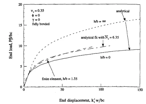
pipeline diameter of 1,066 mm. We observe that the finite-element solution falls within the bounds established by the approximate analytical solutions. Subsequently,_ the approximate solution was obtained as indicated オセゥョァ@ a depth factor N, of 6.35. It should be emphasized that this value of N, was obtained by a trial-and-error procedure and without applying any rigorous analysis such as a least-squares analysis. We note that though the load-displacement matches quite well, the bending moment-load-displacement match is closer to that of hlb = oo case. We should keep in mind that stress predictions using the displacement-finite-element technique are known to be poor, though not always; this would be especially expected in light of the coarse discretization used for the pipeline. It can be appreciated that a variety of approximate solutions can be easily obtained by varying this depth factor that corresponds to the specific hlb ratio.
Laterally Loaded Pile with and without Separation
Pollalis (1982) examined the behavior of a laterally loaded pile allowing for separation to take place as the lateral load was increased monotonically. The soil medium was considered to be elastoplastic, but both elastic shear modulus and the undrained shear strength increased linearly with depth since such a situation is usually encountered in normally consolidated clays. The laterally loaded pile was simulated using cubic beam finite elements for the pile and solved using 3D brick finite elements for the surrounding medium. The separation was accounted for by using discrete spring ele-ments; details can be found in Pollalis (1982). The constitutive model as proposed by Kavvadas (1982) for nonlinear behavior of the surrounding soil
1442
-__,.---was used. However, before proceeding to compare the finite-element so-lutions with the approximate soso-lutions it is important to bear in mind that the solutions obtained by Pollalis (1982) consider shear strength increasing linearly with depth, whereas the proposed solution for a beam embedded in an elastoplastic medium and the solutions for anchors obtained by Rowe and Davis (1982) are only pertinent for a homogeneous medium. Also, we should keep in mind that the solutions for an embedded anchor are those corresponding to that of a plime-strain situation. Here, we attempt to obtain (at least qualitatively) a solution for a complex 30 situation using simplified 20 solutions and no suggestion is made that the analysis is rigorous. None-theless, it does provide insight into the mechanisms involved in the behavior of a laterally loaded pile.
Trochanis et al. (1991a) performed a 30 finite-element analysis of laterally loaded piles that accounted for a nonlinear response of the soil as well as slippage and separation between the pile and the surrounding soil. Subse-quently, Trochanis et al. (1991b) developed a discrete numerical Winkler model that adequately represents the cited nonlinearities, which was vali-dated by solving the same problem using 30 finite-element analysis. A good comparison was obtained for typical test problems. A particular problem that was solved using the discrete numerical Winkler model was that of a laterally loaded pile embedded in a homogeneous cohesive soil.
The solutions as indicated by Pollalis (1982) are expressed in terms of different nondimensional load-displacement parameters that we have se-lected in the foregoing solution. Hence, the 30 finite-element solution given by Pollalis (1982) was transformed to conform to our nondimensional pa-rameters. It is important to note that when separation is not allowed for, Pollalis (1982) obtains an immediate nonlinear response since a linearly varying elastic modulus with depth is used for the surrounding soil medium.
0.8
"
Ee=
0..-g
0.5 ..sa '0 セ@ 0.3 v, = 0.35 $ =0 1 =0 / . ("'./\
.
/ ' . / / . with separation - - 0:=2456 - - - . <x=4912 - - a.= 12280 - -a= 15130. "=
24560 - · - a= 15130-w/sepEnd displacement, k: w /be
FIG. 8. Nondlmensional lッ。、セdゥウーャ。」・ュ・ョエ@ Curve for Laterally Loaded Pile with
and without Separation, 30 Finite Elements [Data from Pollalls (t982)]
1443
'
!
u
\セMMMMMMMMMMMMMMMMMMMMMMMMMMMMMMMMMMML@ 15 10 5 v, =0.35 $ =0 y=O fully bonded
hlb=;: _____ _
--r-analytical 3D finite elements (Trochanis et al., 1991)\
MセM
セMセNZMᄋ@
NZNMセᄋM
-·
_ _ . _ - h l b = I3MD finite elements (Pollalis, 1982)
End displacement,
k:
w /beFIG. 9. Nondlmenslonal Load-Displacement Curve for Laterally Loaded Pile キセィᆳ
out Separation, Analytical versus 30 Finite Elements
セイMMMMMMMMMMMMMMMMMMMMMMMMMMMMMMMMMMMMMMMMMN@ 15 r-v, = 0.35 $ =0
r=o
analyticalI
no separation--30 finite elements (Trochanis et al., 1991)
10-w/separation - upper bound ·
.
. -1 3-:ヲゥセゥセ@
:l:m!nts
(Pollalisi" 1982) P ッセMMセセMMセセセUセPセセMMセセセセiPPセセセセセMMセセQUP@ 5 - I! /
セ@
End displacement. k: w /be
FIG. 10. Nondimensional Load-Displacement Curve for Laterally Loaded Pile with Separation, Analytical versus 3D Finite Elements
Consequently, data from Pollalis (1982) were adjusted to include the initial elastic behavior.
Fig. 8 shows the 3D normalized finite-element solutions as indicated earlier. Pollalis (1982) presented a load-displacement response for a laterally loaded pile in terms of the parameter, <i = Ellii'0b4 This meant that one
particular response curve is required for a specific value of <i. As shown in Fig. 8, the parameter, <i = Ellii'0b
4
, is brought naturally into the proposed
normalization and the resulting response is within a very narrow band. It indeed appears that our normalization is more consistent than that proposed by Pollalis (1982). By comparing Fig. 8 with Figs. 9 and 10, it is evident that the responses obtained by Pollalis (1982) were within a limited range of values for nondimensional loads and displacements; hence an extrapo-lation procedure was used to compare his results with the proposed ap-proximate solution over a wider range of values. It is necessary that we use a rational methodology in order to account for the linear variation of soil properties with depth and obtain a fair comparison between the approximate analyses and the results from the 3D finite-element analyses performed by Pollalis (1982). Two soil profiles were considered, one with constant shear strength and the other w1th shear strength increasing with depth. Further-more, as an approximation, a triangular displacement profile for lateral displacement was assumed. Subsequently, the total work done for the two soil profiles for a unit displacement at the head of the pile was equated; we find that the 3D finite-element response must be amplified by 1.5 to maintain equivalence for the total work done between the two systems. Fig. 9 shows the 3D finite-element solution as compared with the upper and lower bounds obtained using approximate analysis. The approximate solution can be seen to steadily increase from the hlb = 0 case to reach a steady-state solution in which h/b is in the range of 1 to 3. In spite of the cited limitations, it can be observed that the approximate analysis remarkably traces the trend of the more accurate finite-element solution. The data from specific analysis of a laterally loaded pile that accounts for separation given by Trochanis et al. (1991b) were transformed to our non dimensional parameters; the responses are indicated in Figs. 9 and 10.
The separation between the back of the pile and the soil can be accounted for in an approximate manner if we use the corresponding limiting solutions for horizontal anchors as given by Rowe and Davis (1982). Though the limiting resistance depends on the particular collapse criteria used, the upper and lower resistances can be estimated to be in the range of 2c to 4c. Fig. 10 shows the comparison of the characteristic load-displacement curves ob-tained using the proposed analytical approximate solution, the 3D finite-element solution (Pollalis 1982) and the discrete Winkler model (Trochanis et al. 1991). We note that the trend of the load-resistance curve is similar to that of the lower bound (hlb = 1) case. Perhaps this observation provides a rational understanding of this commonly used criterion for ignoring the resistance offered by the soil medium in this region.
CONCLUSIONS
A simple analytical formulation for a beam on an elastic-plastic foundation is presented. The 2D plane-stress-load-displacement solutions developed by Rowe and Davis (1982) were incorporated with the analytical formulation to obtain an approximate 3D solution. This approximate solution was com-pared with the 3D finite-element solution for a shell pipe embedded in an elastoplastic medium. We have demonstrated that the bounds established
by the approximate solutions are quite adequate. The approximate solution can be fine-tuned to the finite-elemen_t solution using the bearing-capacity factor N,. We found that a value of N, セ@ 6.35 matches the displacements well, but that the match of the stresses is not all that satisfactory. The approximate solution was also used to predict the effective lateral pile-head stiffness, and similar trends are predicted.
ACKNOWLEDGMENT
We gratefully acknowledge the financial support provided through grants by the Natural Sciences and Engineering Research Council of Canada and Esso Resources Canada Ltd. for carrying out studies on the problem of frozen soil-pipeline interaction. The first writer also wishes to thank Gulf Canada Resources Ltd. for a studentship awarded through the University of Alberta, Edmonton, Canada.
APPENDIX 1. REFERENCES
"ADINA-a finite element program for automatic dynamic incremental nonlinear analysis." (1987). Rep. ARD 87-1, ADINA R&D, Inc., Boston, Mass.
Bathe, K. J., and Dvorkin, E. (1986). "A formulation of general shell elements-the use of mixed interpolation of tensorial components." Int. J. for Numerical
Methods in Engrg., 22(3), 697-722.
Boyle, J. T., and Spence, J. (1983). Stress analysis for creep. Butterworths, London, England.
Glen, J. W. (1955). "The flow law of polycrystalline ice." Proc., Royal Society, London, England, 228A, 519-538.
Hetenyi, M. (1974). Beams on elastic foundation. University of Michigan Press, Ann
ArbOr, Mich.
Kavvadas, M. (1982). "Non-linear consolidation around driven piles in clays," Sc.D. thesis, Massachusetts Institute of Technology, Boston, Mass.
Konrad, J.-M., and Morgenstern, N. (1983). "Frost susceptibility of soils in terms of their segregation potential." Proc., Permafrost: 4th Int. Conf., National a」。、セ@
emy Science, Washington, D.C., 660-665.
Konrad, J.-M., and Morgenstern, N. (1984). ''Frost heave of chilled pipelines buried in unfrozen soils." Can. Geotech. }., 21, 100-115.
Ladanyi, B. (1972). "An engineering theory of creep of frozen soils." Can. Geotech.
J.' 9, 63-80.
McRoberts, E. C., Law, T., and Murray, T. (1978). "Creep testing on undisturbed ice-rich silt." Proc., 3rd Int. Permafrost Conf., National Research Council, Ed-monton, Alberta, Canada, 539-545.
Morgenstern, N. R., Roggensack, W. D., and Weaver, J. S. (1980). "The behavior of friction piles in ice and ice-rich soils." Can. Geotech. J., 17, 405-415. Nixon, J., Ellwood, J., and Slusarchuk, W. (1981). ''In-situ frost heave testing using
cold plates." Proc., 4th Canadian Permafrost Conf., NRCC, Canada, Section 7,
466-474.
Nixon, J. F., Morgenstern, N. R., and Ressor, S. N. (1983). "Frost heave-pipeline interaction using continuum mechanics." Can. Geotech. J., 20, 251-261. "An overview of the Alaska highway gas pipeline: the world's largest project."
(1978). Proc., Nat. Convention, ASCE, New York, N.Y.
Penner, E., and Ueda, T. (1978). "A soil frost susceptibility test and a basis for interpreting heaving rates." Proc., 3rd Int. Permafrost Conf., Edmonton, Alberta, Canada, 722-727.
Pollalis, S. N. (1982). "Analytical and numerical techniques for predicting the lateral stiffness of piles," PhD thesis, Massachusetts Institute of Technology, Boston, Mass.
Ponter, A. R. S., Palmer, A. C., Goodman, D. 1., Ashby, M. F., Evans, A. G., 1446
and Hutchinson, J. W. (1983). "The force exerted by a moving ice sheet on an
offshore structure." Cold Regions Sci. and Techno/., 8(2), 109-118.
Rowe, R. K., and Davis, E. H. (1982). "The behavior of anchor plates in clay." Geotechnique, London, England, 32(1), 9-23.
Sayles, F. H. (1973). "Triaxial and creep tests in frozen Ottawa sands." Proc., 2nd
Int. Conf. on Permafrost; North American Contribution, National Academy of
Sciences, Washington, D.C., 384-391.
Sayles, F. H., and Haines, D. (1974). "Creep of frozen silt and clay." Tech. Rep.
252, U.S. Army Cold Regions Research and Engineering Laboratory, Hanover,
N.H.
Sego, D. C., and Morgenstern, N. (1983). "Deformation of ice under low stresses." Can. Geotech. 1., 20(4), 587-602.
Sego, D. C., and Morgenstern, N. (1985). "Punch indentation of polycrystalline
ice." Can. Geotech. J., 22(2), 226-233.
Selvadurai, A. P. S. (1988). "Mechanics of soil-pipeline interaction." Proc. Annu. Conf., Canadian Society for Civil Engineering, Calgary, Alberta, Canada, 3,
151-173.
Trochanis, A.M., Bielak, J., and Christiano, P. (199la). "Three-dimensional
non-linear study of piles." J. Geotech. Engrg., ASCE, 117(3), 429-447.
Trochanis, A. M., Bielak, J., and Christiano, P. (1991b}. "Simplified model for analysis of one or two piles." J. Geotech. Engrg., ASCE, 117(3}, 448-466. Trautmann, C. H., O'Rourke, T. D., and Kulhawy, F. (1985). "Uplift
force-dis-placement response of a buried pipe." J. Geotech. Engrg., ASCE, 111(9}, 1061-1076.
Vesic, A. S. (1961). "Bending of beams resting on isotropic elastic solid." J. Engrg.
Mech. Div., ASCE, 87(2), 35-53.
Yamada, S. E. (1988). "Beams on partially yielded foundation." J. Engrg. Mech.,
ASCE, 114(3), 353-363.
APPENDIX II. NOTATION
The following symbols are used in this paper: B creep proportionality constant;
b = beam width (pipeline or pile diameter);
c,
constants;c = cohesion;
E
= beam elastic modulus;E,
= soil elastic modulus;F, = medium resistance per unit length;
h embedment depth;
I beam moment of inertia;
k'
'
foundation subgrade modulus; M = bending moment;N,
= bearing-capacity type factor;N, nondimensional parameter for evaluating soil resistance; n creep exponent in Norton relation;
p nondimensionalload parameter;
pl load level beyond which inelastic strains are induced in surrounding soil;
Pz = load level beyond which inelastic strains are induced in soil as well as in pipeline;
P, = load level beyond which pipeline section is fully plastic;
s
= shear;s. = undrained shear strength;
1447
i!
U,
=
limiting elastic displacement of soil;w displacement in z-direction;
W0 elastic end displacement in z-direction;
W nondimensional displacement parameter;
x ::;:: longitudinal coordinate axis;
i region in plastic state;
x
point of maximum bending moment;z = axis normal to x-axis;
a
non-dimensional parameter defined by Pollalis (1982) ( = Elli70b');'Y soil unit weight;
Ey strain at yield in steel pipeline;
eo
proof strain rate;vs = soil Poisson's ratio;
a o = proof stress;
i70 = stress at tip of pile [used by Pollalis (1982)]; and
- a, yield stress of surrounding medium.
1448
r I
![FIG. 2. Load-Displacement Curves for Rigid Anchors, No Separation [after Rowe and Davis (1982)]](https://thumb-eu.123doks.com/thumbv2/123doknet/14236625.486233/11.594.79.524.489.822/load-displacement-curves-rigid-anchors-separation-rowe-davis.webp)
![FIG. 3. Load-Displacement Curves for Rigid Anchors, with Separation [after Rowe and Davis (1982)]](https://thumb-eu.123doks.com/thumbv2/123doknet/14236625.486233/12.570.57.506.56.394/load-displacement-curves-rigid-anchors-separation-rowe-davis.webp)
![FIG. 8. Nondlmensional lッ。、セdゥウーャ。」・ュ・ョエ@ Curve for Laterally Loaded Pile with and without Separation, 30 Finite Elements [Data from Pollalls (t982)]](https://thumb-eu.123doks.com/thumbv2/123doknet/14236625.486233/16.581.48.503.487.814/FIG8NondlmensionallッセdゥウーャュョエCurveforLaterallyLoadedPilewithandwithoutSeparation3FiniteElementsDatafromPollallst.webp)

