HAL Id: hal-00432240
https://hal.archives-ouvertes.fr/hal-00432240
Submitted on 15 Nov 2009HAL is a multi-disciplinary open access archive for the deposit and dissemination of sci-entific research documents, whether they are pub-lished or not. The documents may come from teaching and research institutions in France or abroad, or from public or private research centers.
L’archive ouverte pluridisciplinaire HAL, est destinée au dépôt et à la diffusion de documents scientifiques de niveau recherche, publiés ou non, émanant des établissements d’enseignement et de recherche français ou étrangers, des laboratoires publics ou privés.
Trap-loaded pyramidal Tri-band antenna for satellite
applications
Sami Hebib, Hervé Aubert, Olivier Pascal, Nelson Fonseca, Lionel Ries,
Jean-Marc Lopez
To cite this version:
Sami Hebib, Hervé Aubert, Olivier Pascal, Nelson Fonseca, Lionel Ries, et al.. Trap-loaded pyra-midal Tri-band antenna for satellite applications. Antennas and Propagation Society International Symposium, 2008, IEEE, Jul 2008, San Diego, United States. pp. 1-4, �10.1109/APS.2008.4619443�. �hal-00432240�
Trap-Loaded Pyramidal Tri-Band Antenna for Satellite Applications
Sami Hebib* (1, 2), Hervé Aubert (1, 3), Olivier Pascal (2), Nelson J.G. Fonseca (4), Lionel Ries (4) and Jean-Marc E. Lopez (4)
(1) LAAS-CNRS, University of Toulouse, 7 Avenue du Colonel Roche, 31077 Toulouse, FRANCE
(2) LAME-UPS,University of Toulouse, 118 Route de Narbonne, 31062 Toulouse, FRANCE
(3) INPT-ENSEEIHT, 2 Rue Charles Camichel, 31071 Toulouse, FRANCE (4) CNES, 18 Avenue Edouard Belin, 31401 Toulouse, FRANCE
E-mail: [email protected]
Introduction
In recent years, several researchers have devoted large efforts to develop radiating devices that satisfy the demands of the satellite telecommunication industry for improved performances in terms of multiple frequency bands and miniaturization. Multi-band antennas are often considered on satellite systems to reduce the number of onboard or ground antennas, combining several applications on the same antenna. Recently, a circularly polarized tri-band GPS/Galileo/TM MicroSat antenna based on a pyramidal structure was presented by the authors in [1-2]. In this previous report, the design and measurement have been performed considering ideal trap-loads, that is, loads replaced by short- or open-circuits. Here the trap-loads of the pyramidal tri-band antenna are characterized by their measured S-parameters and the resulting measured frequency performances and radiation patterns are presented and discussed.
Pyramidal tri-band antenna description
The antenna was required to operate simultaneously in the E5a, E5b and L1 frequency bands of the Galileo and GPS positioning systems and in the MicroSat Telemetry (TM) frequency band. Hence, the frequency plan of the antenna is the following:
• E5a/E5b: 50 MHz bandwidth centered at 1.197 GHz. • L1: 24 MHz bandwidth centered at 1.575 GHz. • MicroSat TM: 90 MHz centered at 2.245 GHz.
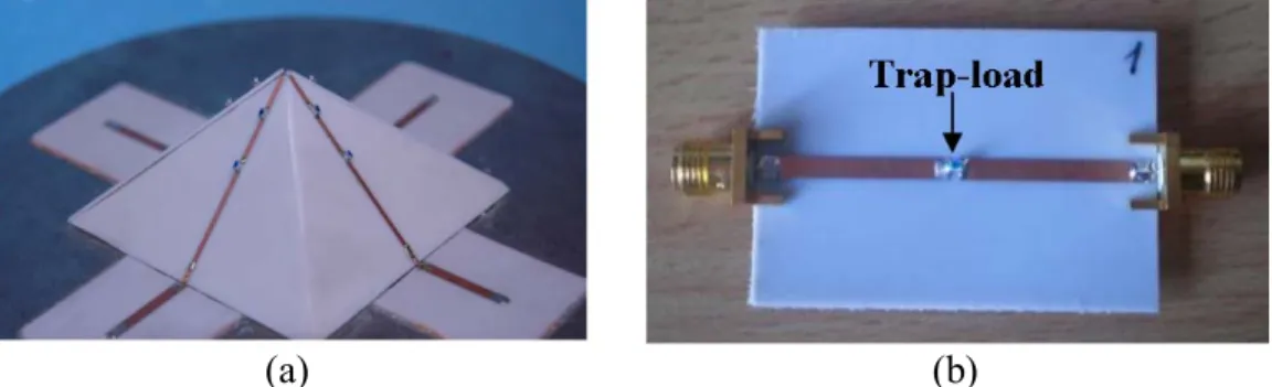
Return loss lower than -10 dB is required at the input port of the antenna and radiation characteristics are also specified for the three previously mentioned operating frequency bands. Figure 1(a) shows the original pyramidal tri-band antenna proposed recently by the authors [1]. It is composed of four printed wires forming a pyramid with a base angle of 45°. The ground plane is circular with a hole in the center, which was found to improve the return loss of the radiating wires. For mechanical constraints, four 50 Ohms microstrip lines are used to shift
the feeding points of the antenna away from the central hole. Finally, a metallic cylinder is placed beneath the ground plane in order to reduce the rear radiation through the hole. The design process of the pyramidal tri-band antenna (see [2]) considers ideal trap-loads, that is, loads replaced by short- or open-circuits depending on the considered frequency. Here the measured S-parameters of these loads replace the ideal equivalent circuit and are taken into account in the design.
(a) (b)
Figure 1 – (a) Top of the trap-loaded pyramidal tri-band antenna and (b) board for the measurement of the trap-loads S-parameters
Trap-loads design
Ideal trap-loads are LC-parallel circuits characterized by a rejected frequency band defined around the center frequency fc =1
(
2π LC)
. These trap-loads are designed to produce an open-circuit at the considered frequencies, thus defining the length of the wire contributing to the radiation at a given frequency. MuRata chip capacitors (C) and inductors (L) are chosen here for their compactness and reliability. The design process of the trap-loads is performed as follows:• First, using the resonant frequency formula of a LC-parallel circuit and the nominal values of the different components given by MuRata, relevant couples (L,C) are selected for obtaining resonant frequencies close to the desired operating frequencies.
• Then, the chips are mounted on small boards (Figure 1(b)) and the S-parameters of the trap-loads are experimentally obtained.
• Finally, from the rejected band of the measured trap-loads, the configuration given in table 1 is finally chosen.
Component Value Reference number
inductor 4.3 nH LQW18AN4N3C00 Trap-load components for
TM MicroSat band Capacitor 1.2 pF GQM1885C2A1R2CB01 inductor 12.0 nH LQW18AN12NG10 Trap-load components for
L1 GPS/Galileo band Capacitor 0.75 pF GQM1885C2AR75CB01 Table 1 – Trap-loads components for TM MicroSAT and L1 GPS/Galileo operating
Trap-loaded antenna measurements
The obtained input return loss is depicted in Figure 2. The highest and intermediate operating frequencies of the tri-band antenna, that is, frequencies related to our choice of the trap-loads, are very close to the expected ones. By reducing the total length of the radiating wires it is possible to finely adjust the lowest operating frequency at the desired value (1.197GHz). Complementary simulations revealed that this frequency shift can be anticipated since it is predicted by the simulations results. The shift is due to the fact that the total length of the wires was defined considering ideal traps. Nevertheless, the presented results reveal the potential of this antenna. The measured bandwidths are respectively 53, 43 and 55 MHz. If a generic design is required, the higher bandwidth needs to be improved. But the MicroSat TM application requires actually a very low bandwidth inside the allowed bandwidth, which means that the problem may be overcome by 2 or 3 generic designs covering different portions of the TM band.
Figure 2 – Input return loss of the trap-loaded pyramidal tri-band antenna
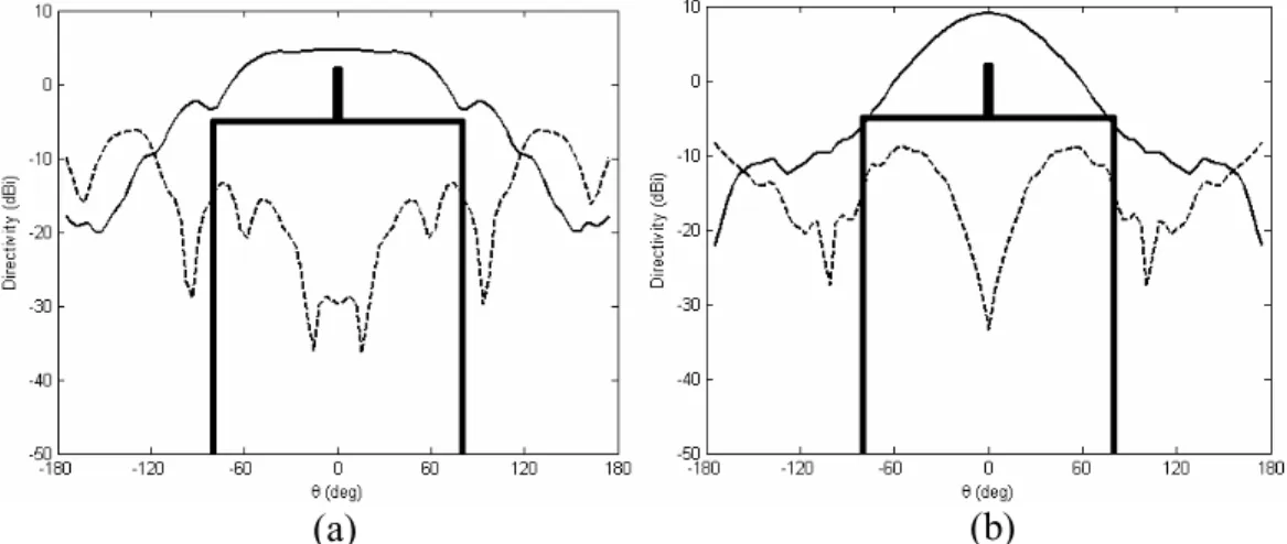
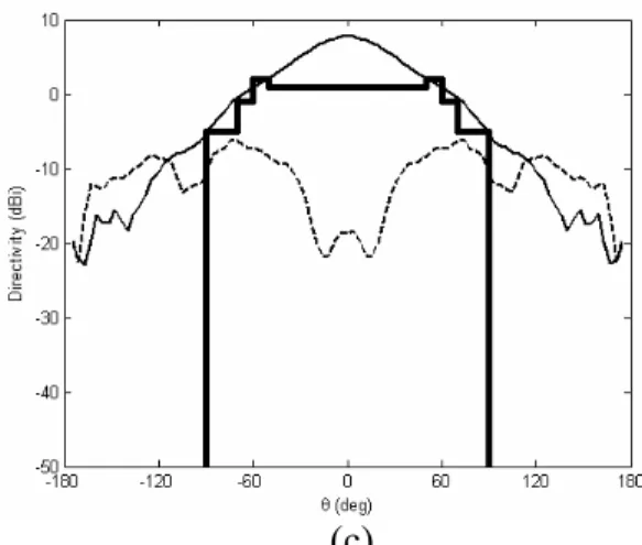
Figure 3 displays the measured Right Handed (RH-) and Left Handed (LH-) Circular Polarization (CP) directivity patterns of the antenna at the three operating frequencies.
Figure 3 – The measured radiation patterns for the multi-band antenna at: (a) 1.06 GHz, (b) 1.57 GHz and (c) 2.23 GHz (―) RH-CP; (---) LH-CP and ( ) Minimum required RH-CP
The measured radiation patterns are in good agreement with the nominal required specifications in the first and second frequency bands (i.e., GPS/Galileo bands). In the highest frequency band (TM MicroSat), the patterns are slightly out of the technical requirements in some radiating directions. This can be improved by adjusting the base angle of the radiating wires.
Conclusion
A novel multi-band circular polarization antenna based on pyramidal structure and trap-loads was designed and tested experimentally. The measured S-parameters of trap-loads have been taken into account in the design for obtaining the technical requirements of the antenna. The measurement results confirm the tri-band behavior of the antenna in the GPS/Galileo and TM MicroSat frequency bands. The proposed radiating structure can also be adapted to combine other satellite applications, like S-band Digital Multimedia Broadcasting.
Acknowledgement
The authors would like to thank D. Kitenge, Murata Electronique S.A.S., France, for offering the chip components used in the frame of this study.
References
[1] S. Hebib, H. Aubert, O. Pascal, N. Fonseca, L. Ries, and J.-M. Lopez, “Pyramidal multi-band antennas for GPS/Galileo/MicroSat applications,” IEEE AP-S Int. Symp., Honolulu, Hawaï, USA, 2007, pp. 2041-2044.
[2] S. Hebib, H. Aubert, O. Pascal, “Multi-band antennas for GPS/Galileo applications,” Final Report, CNES contract: 60168/00, CNES, Dec. 2006, 47 pages.