Chemical Vapor Deposition of Antimicrobial Polymer Coatings
by Tyler P. Martin M. S. in Chemical Engineering University of Maine, 2002 B. S. in Chemical Engineering University of Maine, 2000Submitted to the Department of Chemical Engineering in Partial Fulfillment of the Requirements for the Degree of DOCTOR OF PHILOSOPHY IN CHEMICAL ENGINEERING
AT THE
MASSACHUSETTS INSTITUTE OF TECHNOLOGY
February 2007
C Massachusetts Institute of Technology, All Rights Reserved
Signature of Author: ... V h... ...
Department of Chemical Engineering January XX, 2007
C ertified by: ... ... Karen K. Gleason Professor of Chemical Engineering Thesis Supervisor
Accepted by: ...
William Deen Professor of Chemical Engineering
MASSACHUSETTS Chairman, Committee for Graduate Students
OF TECHNOLOGY
JUN
1 12007
ACHIVES
Chemical Vapor Deposition of Antimicrobial Polymer Coatings
by
Tyler P. Martin
Submitted to the Department of Chemical Engineering on January 10, 2007 in Partial Fulfillment of the
Requirements for the Degree of
Doctor of Philosophy in Chemical Engineering ABSTRACT
There is large and growing interest in making a wide variety of materials and surfaces antimicrobial. Initiated chemical vapor deposition (iCVD), a solventless low-temperature process, is used to form thin films of polymers on fragile substrates. To improve research efficiency, a new combinatorial iCVD system was fabricated and used to efficiently determine the deposition kinetics for two new polymeric thin films, poly(diethylaminoethylacrylate) (PDEAEA) and poly(dimethylaminomethylstyrene) (PDMAMS), both candidates for antimicrobial coatings. Fourier transform infrared (FTIR) spectroscopy shows that functional groups are retained in iCVD of PDMAMS and PDEAEA, whereas essentially all fine chemical structure of the material is destroyed in plasma-enhanced CVD. It was found that the combinatorial system in all cases provided agreement, within experimental certainty, with results of blanket iCVD
depositions, thus validating the use of the combinatorial system for future iCVD studies. Finished nylon fabric was subsequently coated with PDMAMS by iCVD with no affect on the color or feel of the fabric. Coatings PDMAMS of up to 540 pg/cm2 were deposited on fabric. A coating of 40 pg/cm2 of fabric was found to be very effective
against gram-negative E. coli, with over a 99.9999%, or 6 log, reduction in viable bacteria in one hour. A coating of 120 pg/cm2 was most effective against the
gram-positive B. subtilis. Further tests confirmed that the iCVD polymer did not leach off the fabric.
Type-II photoinitiation was utilized to perform vapor phase deposition of covalently-bound polymer coatings of the polymer PDMAMS. The durability was improved so that 80 wt% of the fabric coating was retained after extended antimicrobial testing and three rounds of ultrasonication. The coating was effective, killing 99.9% of E. coli in one hour. The gCVD process was then further explored using the less-UV-sensitive monomer DEAEA for deposition onto spun cast PMMA thin films. Durable films up to 54 nm thick retained 94% of their thickness after 10 rounds of ultrasonication. Gel Permeation Chromatography (GPC) and Variable Angle Spectroscopic Ellipsometry (VASE) swelling cell measurements gave estimated ranges of 72-156 kDa for the molecular weight and 0.1-0.24 chains/nm2 for the graft density.
Thesis Supervisor: Karen K. Gleason Title: Professor of Chemical Engineering
Acknowledgements
My time at MIT has been an incredible experience. For that I owe thanks to a great many people for their guidance, support, friendship, and advice.
First, my adviser Karen has been a great mentor in this business of research. Your patience and prodding through the process of defining a project, encouragement and trust through the middle stages when it seemed no end was in sight and enthusiasm as positive results came in provide a great example of what an adviser should be, and I can only hope to emulate your example.
My thesis committee members, Professors Klavs Jensen and Paula Hammond, generously spent their time and offered advice over the course of the thesis and for that I am grateful. In particular, Prof. Jensen suggested what became a fruitful collaboration with his own research group and I greatly appreciate that experience.
Being a member of the Gleason group has provided me with interactions with a most amazing group of individuals I have ever had the opportunity to work with, and I owe thanks to many members past and present for their help, advice and friendship. Ken Lau (currently a Professor at Drexel) trained me in nearly every critical arena and offered much help and guidance over the course of my thesis. I knew Shashi and Dan (both currently Professors at Northeastern) for a short time, yet both left their mark on me with their professionalism and encouragement in the earliest stages of my work. Kelvin was and is a good friend in life and research, and contributed great ideas to my thesis, whether he knows it or not. Shannan has been a great friend, sounding board and devil's
advocate, never afraid to say exactly what he is thinking, and precisely what is needed at times. Wyatt, Sal, and Malancha joined the group well after us, providing the first opportunity for explaining ourselves and have been valuable friends and colleagues throughout.
Two undergraduate students have provided invaluable assistance. Stephanie was instrumental in getting the group's first bacterial testing facilities and procedures up and running. She was of great assistance in the work outlined in Chapter 3. Kyra Sedransk has been extremely helpful in the grafting work outlined in Chapter 4. I greatly enjoyed the opportunity to be a part of their undergraduate experience and hope it was fruitful for them as well.
There have been innumerable others at MIT who have affected my life. First, the Hedge: Ben (1s yr survival partner), Eric, Ryan, and Joel brought new intellectualism to my hobby time, to say the least, as well as becoming what I hope are lifelong friends. Jake, Kris, Jane, Mark, Jodi, Theis and many more that slip the mind at this hour made the first semester slightly more bearable as well as partners in fun the next four years and are part of what has made this an unforgettable experience.
My parents instilled a lifelong love of learning along with unconditional support and love, and words simply can't express my gratitude.
Finally, my wife Andrea is most deserving. Without her I never would have had the courage to attempt this nor the fortitude to complete it. Plus, she had to put up with
my stress as much as I did, always willing to shoulder part of the load, listening to my rants and sharing in the excitement. For this I am eternally grateful.
Table of Contents Title Page 1 Abstract 2 Dedication 3 Acknowledgements 4 Table of Contents 5 List of Figures 7 List of Tables 11 Chapter 1: Introduction 12
1.1 Combinatorial Initiated Chemical Vapor Deposition 13
1.2 Antimicrobial Technologies 21
1.3 Grafting Chemical Vapor Deposition 26
1.4 Scope of Thesis 29
1.5 References 30
Chapter 2: Combinatorial Initiated Chemical Vapor Deposition for
Polymeric Thin Films 35
2.1 Abstract 36
2.2 Introduction 37
2.3 Experimental 39
2.4 Results and Discussion 44
2.4.1 Acrylate monomer: (diethylamino)ethyl acrylate 44 2.4.2 Styrenic monomer: (dimethylamino)methyl styrene 50
2.5 Conclusion 55
2.6 References 56
Chapter 3: Initiated Chemical Vapor Deposition of Antimicrobial
Polymer Coatings 58
3.1 Abstract 59
3.2 Introduction 60
3.3 Experimental 62
3.4 Results and Discussion 66
3.5 Conclusion 74
Chapter 4: Solventless Surface Photoinitiated Polymerization:
Grafting Chemical Vapor Deposition (gCVD) 77
4.1 Abstract 78
4.2 Introduction 78
4.3 Experimental Details 81
4.4 Results and Discussion 86
4.5 Conclusion 95
4.6 References 96
Chapter 5: Conclusions and Future Work 98
5.1 Conclusions 99
6.1.1 Combinatorial Initiated Chemical Vapor Deposition 99
6.1.2 Antimicrobial Coatings 100
6.1.3 Grafted Antimicrobial Coatings 101
5.2 Future Work 101
Appendix A: Organic High-K Dielectric 104
Appendix B: Grafted Superhydrophilic Scleral Lens Coating 110
List of Figures Chapter One
Figure 1-1. Initiated CVD results from Jessie Mao on PGMA deposition. The excellent examination of precursor ratios and filament temperature effects on growth rate and molecular weight required nearly a semester's worth of work. The points indicated by the dotted lines could all be deposited simultaneously using combinatorial iCVD, greatly reducing the time required for such important but rather tedious exploration of process parameters. 13 Figure 1-2. Images from Wang ' a) Library of 16 discreet samples deposited serially using a mask, each spot at different conditions. b) Schematic of a system for deposition of thickness gradient films. Each strip is deposited at different conditions. 17 Figure 1-3. Images from Gladfelter et al. a) Schematic of combinatorial CVD reactor b) Compositional map of Ti, Sn, and Hf, with map of effective dielectric constant. 18 Figure 1-4. Image from Cassell et al. Combinatorial testing of carbon nanotube growth catalysts, simultaneously testing both surface directing agent (SDA) concentration and catalyst
composition. 19
Figure 1-5. Images from Semancik et al. '. TiO2 films simultaneously grown by CVD on an array of microhotplates, each image is of a film grown at the indicated temperature. 20 Figure 1-6. Hydrogen abstraction by benzophenone through photochemical
excitation 27
Chapter Two
Figure 2-1. Chemical reactants for combinatorial iCVD: a. DMAMS monomer (para-isomer shown, both ortho- and para- (para-isomers utilized) b. DEAEA monomer c. TAP
initiator 40
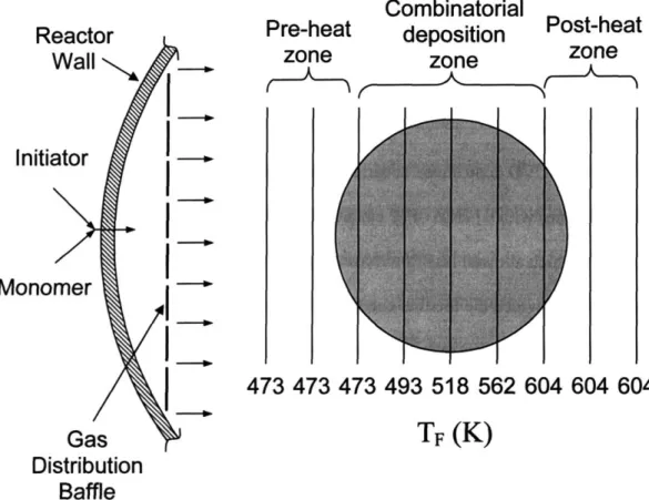
Figure 2-2. Schematic of combinatorial initiated chemical vapor deposition system. Partial top-down view showing gas inlet and distribution using a perforated baffle plate. Filament temperature zones are shown, and each filament is marked with the
corresponding temperature. 40
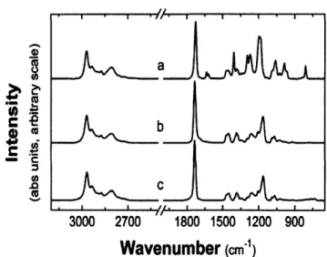
Figure 2-3. FTIR spectra of a) DEAEA monomer with b) blanket-deposited PDEAEA and c) combinatorially-deposited PDEAEA films prepared at the same conditions
(Tflament = 604 K, Tsubstrate = 303 K). 45
Figure 2-4. Combinatorial and blanket growth rate chart for PDEAEA. Temperature of the substrate indicated by symbols: 321 K (A), 312 K (e), and 303 K (m) combinatorial data; all five points at each substrate temperature were obtained simultaneously. Data for blanket deposition at 303 K (o) also shown. Lines indicate the slope for the three lower filament temperatures, which were used to determine the apparent activation energies shown in Table 2-1; solid lines represent combinatorial data and the dotted line is for two
blanket depositions. The slopes for the three combinatorial depositions match within experimental certainty with the slope for the blanket depositions, though the absolute deposition rate is 20% lower at the fastest set of conditions. 45
Figure 2-5. FTIR spectra of a) DMAMS monomer with b) commercially available PDMAMS c) blanket-deposited PDMAMS and d) combinatorially-deposited PDMAMS films prepared at the same conditions (Tfament = 604 K, Tsubstrate = 320 K). e) A film deposited by pulsed-plamsa enhanced CVD from DMAMS monomer. 51 Figure 2-6. Combinatorial and blanket growth rate chart for PDMAMS. Temperature of the substrate indicated by symbols: 320 K (A), 329 K (e), and 338 K (m) combinatorial data; all five points at each substrate temperature were obtained simultaneously. Data for blanket deposition at 320 K (o) also shown. Lines indicate the slope for the three lower filament temperatures, which were used to determine the apparent activation energies shown in Table 3; solid lines represent combinatorial data and the dotted line is for two
blanket depositions. 53
Chapter Three
Figure 3-1. Chemical reactants for combinatorial iCVD: a. DMAMS monomer (para-isomer shown, both ortho- and para- (para-isomers utilized) b. TAP initiator 64 Figure 3-2. Polymer mass added to the fabric is not linear in deposition time. The mass increases slowly at early times and then increases rapidly after about 50 minutes. At least two depositions were performed at each time and error bars represent the standard
error. 68
Figure 3-3. FTIR spectra of DMAMS monomer (a), commercial PDMAMS reference (b), and iCVD PDMAMS (c). The deposited polymer spectrum is consistent with that of the conventionally prepared commercial polymer reference. Peaks associated with the
monomer are marked (*). 68
Figure 3-4. Scanning electron microscopy images of nylon fabric conformally coated with PDMAMS. a. Coating weight of 86 pg/cm2, showing the coating forms conformally
around each fiber. Scale bar indicates 10 pm. The coating does not form bridges and does not coalesce, so pores between the fibers remain open. b. Coated fiber cross-section performed with a focused ion beam (FIB). Coating weight of 204 pg/cm2, corresponding to a thickness of -195 nm. Scale bar indicates 1 pm. Coating is in the area demarcated by arrows. The nylon fiber is inside the curve, and a layer of carbon deposited for FIB purposes lays on top of the coating (see experimental details). 69 Figure 3-5. Results of antimicrobial testing by ASTM E2149-01 against E. coli and B. subtilis. Test performed for 60 minutes. The coating was very effective against both microbes, attaining a >6 log reduction in viable bacteria, though the most effective
coating weight was different for each microbe. Dotted lines are guides for the eye to help demarcate the two sets of results, not best fit lines. 71 Figure 3-6. Leaching tests. a. As deposited coating on nylon fabric is placed on a
confluent film of E. coli. There is no zone of inhibition (ZOI), indicating the active agent is not diffusing off the fabric to kill bacteria away from the edge. Sample shown has coating of 120 pg/cm2, three times the minimum effective coating against E. coli of 40
pg/cm . b. A 1 cm well is bored into an agar plate seeded with a confluent film of E. col. 200 pL of supernatant from the antimicrobial test is placed in the well. After incubation overnight no ZOI is present around the well, indicating there is not sufficient
antimicrobial polymer in the solution to kill the bacteria. 73 Figure 3-7. Time series testing against e. coli at the minimum effective coating thickness found in Figure 2, 40 pg/cm2. It was found that the coating killed -4 log bacteria in just
two minutes, and continued on to kill over 6 log in sixty minutes. 74 Chapter Four
Figure 4-1. Chemical reactants for grafting CVD: a)Monomer: (dimethylamino)methyl styrene (DMAMS), b) Type II Photoinitiator: Benzophenone (BP), c) Monomer:
(2-diethylamino)ethyl acrylate (DEAEA) 86
Figure 4-2. SEM image of gCVD-PDMAMS coated nylon fibers after severe durability testing of 24 hrs swirling at 200 rpm in an orbital shaker in PBS followed by 3 rounds of ultrasonication in DI water. It is clear that the coating remains chiefly intact. (Sample
S1) 88
Figure 4-3. FTIR spectra of a) commercial standard PDMAMS, b) iCVD PDMAMS, and c) gCVD PDMAMS. Peaks attributed to the tertiary amino group at 2700-2850 cm-' are
marked. (Sample S2) 88
Figure 4-4. Durability testing of poly(DEAEA) deposited on spun cast PMMA. a) Poly(DEAEA) deposited by iCVD, with no grafting or crosslinking; 5% of film is retained after one wash. b) Poly(DEAEA) deposited by gCVD; 94% of the film is
retained after ten wash rounds. (Sample P2) 89
Figure 4-5. FTIR spectra of the a) DEAEA monomer, b) iCVD Poly(DEAEA), c) gCVD Poly(DEAEA) (Sample P2). The grafted polymer spectrum is consistent with that of the iCVD polymer. Peaks attributed to the vinyl moiety of the monomer are marked with
asterisks. 90
Figure 4-6. gCVD process optimization. Four deposition variables are explored a) Initiator time (samples BPl -BP4), b) Monomer time (samples MI -M4), c) Monomer pressure (samples P1 -P4), and d) Stage temperature (samples TI -T4). 91
Appendix A
Figure A-I Dielectric constants for PDMAMS films deposited at the indicated filament temperature. All films were deposited at T, = 320 K. Large variation in measurement at low temperature is likely due to the films being very thin. 108 Figure A-2 Dielectric constants for PDMAMS films deposited at the indicated substrate temperature. All films were deposited at Tf = 604 K. 108
List of Tables Chapter One
Table 1-1 Different Techniques of Using Benzophenone as a Photoinitiator 28
Chapter Two
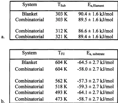
Table 2-1. Apparent activation energy in filament (Eafilament) and substrate (Ea,substrate)
temperature for deposition of PDEAEA. Data for both combinatorial and blanket depositions are shown. a. Ea,filament found at three substrate temperatures (Tsub) using the combinatorial system are slightly lower than that found using the blanket system at one substrate temperature. b. Ea,substrate determined at five filament temperatures are slightly lower than that determined by using the blanket system at one filament
temperature. 48
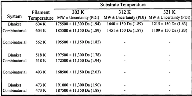
Table 2-2. Gel permeation chromatography was performed to determine the molecular weight of the deposited PDEAEA, and PDI is shown in parenthesis. It has been previously shown by Chan et al. that molecular weight is linearly proportional to the surface concentration, which is a function of the substrate temperature. The uncertainty is estimated from experimental and measurement error. It is clear that the combinatorial system provides the same information as if every point was deposited separately using
the blanket deposition system. 49
Table 2-3. Apparent activation energy in filament (Eafilament) and substrate (Ea,substrate)
temperature for deposition of PDMAMS. Data for both combinatorial and blanket depositions are shown. a. Eafilament found at three substrate temperatures (Tsub) using the
combinatorial system are slightly higher than that found using the blanket system at one substrate temperature. b. Ea,substrte determined at five filament temperatures are generally slightly higher than that determined by using the blanket system at one filament
temperature. 54
Chapter Four
Table 4-1. Details of gCVD Experimental Runs 83
Table 4-2. Molecular weight and graft density found using GPC and VASE swelling cell. GPC provides the maximum MW and minimum graft density, whereas VASE swelling cell data provides the minimum MW and maximum graft density. Thus the two methods
Chapter One
Introduction
1.1 Combinatorial Initiated Chemical Vapor Deposition
The process of chemical vapor deposition has many parameters. The time
consuming process of exploring this large parameter space is exemplified by recent work in our lab completed by Jessie Mao on poly(glycidyl methacrylate).4 The precursor ratios
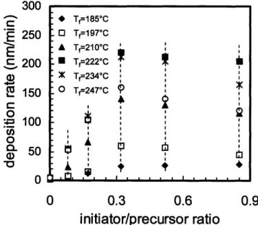
and filament temperature were varied systematically. The resulting growth rate and molecular weight were examined, both of which are critical for the intended application, patternable resist materials. The results of the work are presented in Figure 1-1. This CVD 300 * T,=185*C 250 0 Tf197'C A Tf=21 0*C C 200 E Tf=222*C X Tf=234*C E 150 0 T=247-C 9 0 - 100 0-0 0 0.3 0.6 0.9
initiator/precursor ratio
Figure 1-1. Initiated CVD results from Jessie Mao on PGMA deposition. The excellent examination of precursor ratios and filament temperature effects on growth rate and molecular weight required nearly a semester's worth of work. The points indicated by the dotted lines could all be deposited simultaneously using combinatorial iCVD, greatly reducing the time required for such important but rather tedious exploration of process parameters.
process exploration is somewhat tedious and time consuming, but critical for the optimization of each deposition chemistry attempted. In this case, the work required about one semester. For the standard system, much effort must be expended to ensure the
other experimental conditions are held very near constant to ensure repeatability, which can difficult over four month's worth of experiments while the equipment is shared with one or two other researchers. While the precursor ratios probably cannot be
systematically varied combinatorially (at least in a parallel sample growth scheme), the filament temperatures can. It is theoretically possible to vary all the temperatures
simultaneously, thus depositing the groups of samples indicated by the dotted lines in one deposition experiment. The application of combinatorial techniques can also reduce experiment-to-experiment variation, as fewer experiments results in less variability. The time saved could effectively be used to examine more of the parameter space, such as the effect of pressure and substrate temperature, or move on to application work if the optimization goals have been satisfied.
The application of combinatorial techniques to materials discovery has lagged behind its use in other fields, such as pharmaceuticals, but work in the area is increasing as evidenced by the establishment of NIST's Combinatorial Methods Center in January 2002 as part of the polymers division7. There are many examples of the ways the
combinatorial experimentation concept has been successfully applied, but only a small sample will be presented here, after a short general description of combinatorial research strategies.
There are three essential components that must be in place for large scale combinatorial methods to succeed8. The materials to be tested should be rapidly
produced, either individually in parallel or as part of a continuous gradient. The capability for rapid, preferably parallel, testing of the properties of interest should be in place. Finally, an efficient database system is needed for recording the data gained and
making it readily available to interested parties. Having one or two of these components while disregarding the third simply shifts the discovery bottleneck around while only marginally increasing the pace of discovery. Setting up a new combinatorial discovery system with all three components is very expensive, well out of the reach of most small scale research labs. However, while because of this limitation combinatorial methods are currently applied mainly in industrial settings, they hold promise for individual research groups as well. Often, in a small research lab setting, synthesis of samples covering a range of variables is the bottleneck, and speeding this step of the process can provide large gains, without necessarily having to upgrade testing equipment and data handling as well. This will be shown after a short review of the history of combinatorial materials experimentation and current combinatorial materials discovery strategies.
Hanak9 was one of the first to propose and synthesize a combinatorial library in
1970. He used a system for sputtering binary and ternary targets to produce
compositional gradient thin film libraries, and subsequently tested each substrate along its compositional axis for the desired property, electrical resistance. The strategy of using the line-of-site property of physical deposition processes for the production of
compositional gradient libraries has since become common 10-12. The low availability of
automation and computer equipment hindered the further development of Hanak's ideas for some time. Also, co-sputtering is realistically limited by the number of elements and spread of composition that can be simultaneously tested.
The limitations of Hanak's sputtering technique eventually gave rise to solution techniques 10~12 in which an essentially unlimited number of elements or polymeric
numbers of samples can be synthesized in parallel. A possible issue with these methods is that often the final product will not be synthesized in a similar fashion, and the synthetic method can have a large bearing on the final properties, particularly in the case of catalysis research. While the automatic synthesis of libraries using solution techniques is fascinating, the proposed work will be fundamentally different, and so these techniques will not be examined further here.
More closely related to this work are recent attempts to effectively combine combinatorial methods with chemical vapor deposition (CVD) thin film synthetic techniques. This is desirable because CVD is widely used in various industries, and as mentioned above, it is best to use the same synthetic technique in materials research as that which will be used to make the final product. However, there are issues inherent in
using CVD to produce combinatorial sample libraries in parallel. Since CVD generally is not a line-of-site deposition process, it will be difficult to produce compositional gradient
films by CVD (although one example below does just that). Many of the important factors in CVD processing, such as precursor flows and pressure, can not be varied in parallel without multiple reaction chambers, an expensive prospect.
There have been three strategies employed to apply combinatorial techniques to research on CD systems: sequential deposition of discreet samples through a physical mask 1,13-15, compositional spreads 5,6 using a method somewhat analogous to the above
outlined PVD technique, and varying substrate conditions2'3' 16
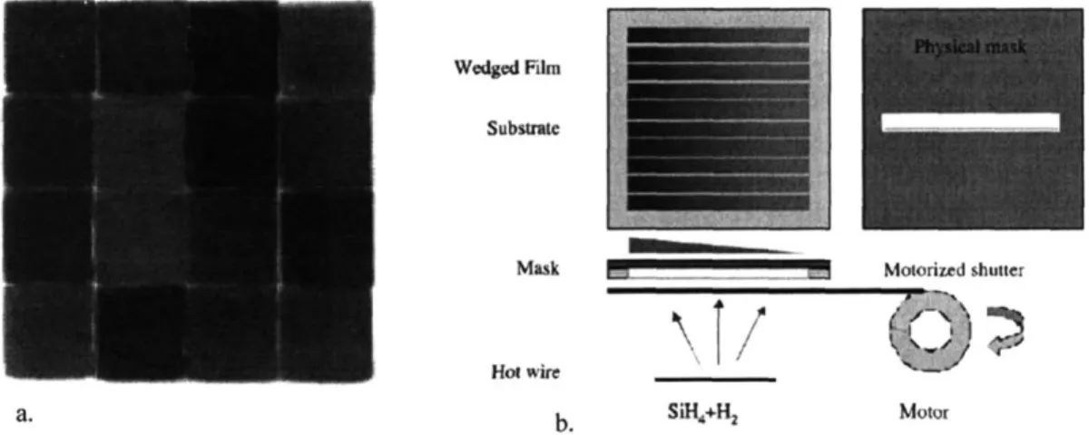
Physical masking techniques have been used to deposit discreet samples sequentially on one substrate 1, 13-15, (Figure 1-2a) saving the time required for loading
which is highly sensitive to the deposition conditions. An advantage of this technique is that several processing conditions can be tested on one substrate, for instance, steadily increasing the pressure for each sample, which would be difficult otherwise.
Additionally, a moving shutter (Figure 1-2b) has been used in conjunction with the mask to produce a series of film thickness gradient samples at varying deposition conditions. This provides a ready method for examining the affect of film thickness on final
properties. The authors also point out the usefulness of the physical masking system for testing the films in a device-like system. The moving shutter can be used to deposit films of varying thickness at different deposition conditions, and then overlay, on the other axis, another ten films. In this way many "devices" of multiple layers can be rapidly produced and film performance can be tested in a more directly in a device-like setting.
Wedged Film
Substrate
Mask Motorized shutter
Hot wire
a. b. SiH4+H2 Motor
Figure 1-2. Images from Wang a) Library of 16 discreet samples deposited serially using a mask, each spot at different conditions. b) Schematic of a system for deposition of thickness gradient films. Each strip is deposited at different conditions.
Similar work on combinatorial deposition of amorphous silicon thin film transistors is is included but not described for brevity.
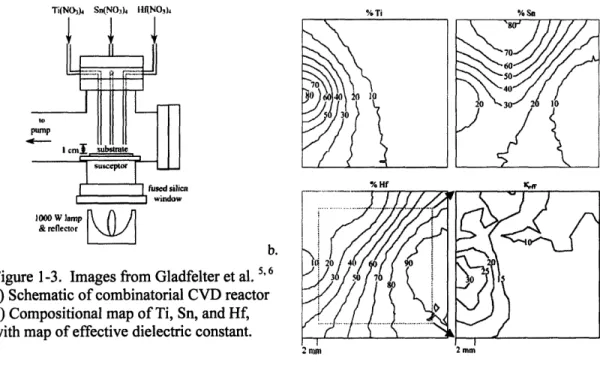
The deposition kinetics and fluid dynamics of CVD have been utilized to make ternary metal oxide compositional spread films 5,6 for study as high k dielectric materials.
By placing the inlet for the reactants directly over the heated substrate, the deposition is highly non-uniform in a circular pattern around the inlet (See Figure 1-3a for a schematic of the reactor). Spacing three separate inlets, each with a separate precursor, results in a ternary compositional spread, as measured by XPS, an example of which is shown in Figure 1-3b, with confirmation by RBS. The film thickness is also highly non-uniform using this method. In this case, the parameter of interest, effective dielectric constant, is automatically corrected for the different thicknesses at each point. However, the
variation in growth rate across the substrate is not an ideal situation for testing other properties, such as adhesion, roughness or conformality. They were able to map the
Ti(NO), Sn(NO.,)4 I1Rf(NO3)s %Ti % Sn
70 60 50 P P0 30 Ical substa Muscept&rL_ fused silica % H window & reflector a. L. ILI1 20 49
Figure 1-3. Images from Gladfelter et al. 60 3 0
a) Schematic of combinatorial CVD reactor
b) Compositional map of Ti, Sn, and Hf, 1 with map of effective dielectric constant.
2nim 2mm
dielectric constant in the same manner the composition was mapped, and therefore find the best composition. The best compositions found by the combinatorial method were then deposited, tested, and confirmed as a single uniform film. This combinatorial
method is similar in technique to the ternary sputtering strategy described above, in the sense that physical spacing determines film composition.
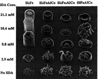
Carbon nanotube (CNT) growth is highly dependent on the substrate catalyst utilized. While technically catalyst research, the work here uses a combinatorial surface treatment scheme with CVD2 for testing the catalyst, and so is of interest here. Figure
1-4 shows the combinatorial placement of catalyst material along one axis and
concentration of an additive along another. The SEM shows clearly which combination of factors gives the desired growth characteristics. The authors also employ a useful strategy wherein a series of combinatorial libraries are fabricated, first a wide parameter discovery library, followed by more focused libraries to pinpoint the optimal catalyst composition.
SDA Conc. ShFe ShFeAJCo ShFwMACo SIFeAlCo
21.2 mM
10.6 M
5.8 muM
2.9 mM
No SDA
Figure 1-4. Image from Cassell et al. 2 Combinatorial testing of carbon nanotube
growth catalysts, simultaneously testing both surface directing agent (SDA) concentration and catalyst composition.
Finally, in the work with the most relevance to the proposed work, individually programmed microhotplates are used to vary the depostion temperature systematically3'
16. The microstructure of deposited titanium dioxide was examined over a wide range of
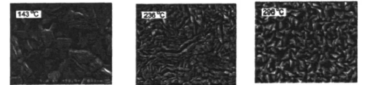
deposition temperatures. In addition, the temperature programming and rapid heating/cooling of such devices meant the authors could ramp or pulse the devices between two temperatures and examine how this affected the microstructure. This work is similar to the proposed in the sense that the deposition temperature is the key variable, and that the molecular and microstructure structure will be key properties, as described below. SEM images of the microstructure obtained at a range of temperatures are shown in Figure 1-5. The obvious drawbacks to the technique include the somewhat arduous fabrication of the microhotplates and limitations on the substrate materials. An
advantage is that the microhotplates with such films on top are investigated for sensing applications, and, as before, it is always an advantage to fabricate the films in the same manner as the hoped-for final application.
143
Figure 1-5. Images from Semancik et al. 3. TiO2 films simultaneously grown by CVD on an array of microhotplates, each image is of a film grown at the indicated temperature.
The value of applying the combinatorial work to monomers which have not previously been deposited by iCVD is to quickly identify the successful process window for deposition and the associated kinetics. In this paper, the results of the combinatorial depositions will be compared to the results of traditional blanket iCVD films to verify if the same chemical structure, growth rate, and other film properties are obtained.
1.2 Antimicrobial Technologies
There is large and growing interest in making a wide variety of materials and surfaces antimicrobial. Textiles and other materials present in a hospital setting have been shown to be sufficient bacterial supports17 raising the possibility that these materials
could be responsible for disease transfer among hospital populations, a common occurrence.'''19 Thus, it may be possible to reduce infection rates by adding
antimicrobial agents to textiles and other surfaces. There has been and continues to be a considerable amount of research into making fabrics antimicrobial to address this and other issues.2 0
-2 9 For instance, self-sterilizing fabrics are also under study for biowarfare protection.29 In addition to fabrics, antimicrobial surfaces are of interest for medical
devices30~39 particularly to combat the insidious problem of biofilm formation,40 and for
reduction of biofouling in water handling systems,41, 4 2 among other areas.
A wide range of antimicrobial agents have been added to surfaces: antiseptics and antibiotics including chlorhexidine, rifampin and monocylcline and others,30~33' 3537 '41 43 44 silver/silver ions/silver compounds,2 0,2 7
,2 8
,31,34,36,45 hydantoin (also known as halamine) compounds,2 1,2 6,2 9,46,4 7 furanone compounds,38'39'48 and quaternary
ammonium22-25,28, 42, 49-5s or phosphonium polymers2 8, 56. There have been a smaller number of non-permanently cationic antimicrobial polymeric materials prepared for use on surfaces, generally incorporating benzoic acid derivatives57'58. While a large number
of other antimicrobial agents have been prepared for use in solution, these are beyond the scope of this work, except Gellman et a159 in which the polymer described within has
The various agents are most often physically applied to the surface,20,27, 3 0,4 5 physically impregnated into the bulk of the material,31 33'35 '36'44 or physically
incorporated into a coating that is then applied to the surface for release.3 2,34 In all these
approaches the antimicrobial agent leaches from the surface, leading to two key
problems: a limited time of effectiveness and environmental, health and safety concerns, such as the promotion of drug resistant microbes. Non-leaching antimicrobial surfaces have been created by covalently grafting an antimicrobial polymer to the surface,21-26,28,
29,42,46,47,49-53 including atom transfer radical polymerization of an antimicrobial polymer
directly from an initiating surface,5 5 and covalent attachment of an agent to a polymer
chain.38'3 9'4 1'4 3'5s In the later case any attachment scheme must not obscure the active
moiety of the molecule.
Antiseptics and antibiotics have generally been employed for medical applications.30~3' - Central venous catheters have been both impregnated with
chlorhexidine and a silver compound3' and coated with rifampin/minocycline on the
exterior and intraluminal surfaces30'60 to successfully reduce the rate of catheter-related
blood stream infections. Each case uses two active agents in an attempt to reduce the promotion of resistant bacteria. These approaches have been successfully
commercialized and are now recommended for use in certain situations,37 and have lead
to significant reductions in mortality and healthcare costs in some hospitals.31'60 There
are concerns about the emergence of drug resistant bacteria,61 (although this is still under study for the specific case of impregnated catheters33) and cases of anaphylactic shock
reaction to chlorhexidine impregnated catheters have been reported.62 Some in the
wherein active agents are released into a compromised patient. In such cases, native and beneficial bacteria populations (i.e. E. coli in the intestines) may be reduced, allowing pathogenic species to gain a foothold in the patient, among other side effects. In addition to central venous catheters, the use of antibiotics has also been explored in such various devices as a coating on wires and pins, impregnated in endotracheal tubes,36 and slow
release from periodontal implants.3 5 In addition to medical devices, antibiotics have been
covalently bound to a polymer backbone for use in a biosensor 3 and water systems.4' In
theory, covalently bound antibiotics would never be released, and so should not promote resistant bacteria. However, it is not yet clear what affect, if any, covalently bound antibiotics may have on the promotion of drug resistant bacteria.
The new antimicrobial polymer coatings under study here are non-leaching. Thus, they would not have a diminished effectiveness over time, greatly reduced incidence of systemic side effects, and, most significantly, it is currently thought that bacteria
probably will not develop resistance to antimicrobial polymers22 although this needs to be
shown for the new polymers under study here.
Silver, silver ions, and silver compounds have been used for a somewhat more varied range of applications. Medical devices impregnated with both an antibiotic and a silver compound were discussed above.31'36 In addition, urinary catheters with a silver
alloy/hydrogel coating have also been examined.34 Various vapor deposition methods
have been employed to coat fabric2 0
,2 7 and polymer/metal surfaces45 with silver. No
matter how the silver component is incorporated it can only work as a leaching agent because it only kills the cells after being taken up by the bacterium. Hence, any system utilizing silver will have a diminished effectiveness over time. The length of
effectiveness can be increased by incorporating more silver, but at some point this becomes untenable. In addition, patient sensitivity to silver compounds and coatings has been reported.63-5 In one case the patient showed no allergic reaction to topical
application of silver ions yet had a strong adverse reaction to internal use of a device coated with silver.65 Finally, some researchers have found bacterial populations that have
developed resistance to silver, similar antibiotic resistance.66'67
Various hydantoin compounds have been successfully incorporated as polymer pendant groups or grafted to fabrics to impart antimicrobial action. Sun et al. have
created a variety of hydantoin moieties and both incorporated them into polymer beads 47 for water purification applications and grafted them onto various textiles21,26 to provide
enhanced protection against bacteria. Worley et al. also created polymer beads with hydantoin pendant groups for water purification.46 The hydantoin moieties are essentially
storage compounds for chlorine, which is released to the bacterium to kill it. In addition, the amine-halogen bond is photosensitive.2 9
Furanones3 8
,3 9 have been incorporated into a polymer matrix and covalently bound to the surface of catheters. These compounds stop the growth of biofilms, a major route to bacterial toxicity attributed to biomaterials,40 by interrupting cell to cell
communication.48 The coating reduced bacterial adhesion to the coated catheters and
reduced level of infection at the implant site in an animal model trial. 38
Numerous quaternary ammonium, and to a lesser extent phosphonium, compounds and polymers have been shown to be effective antimicrobial agents. All these polymers are permanently cationic. This work will mainly be concerned with
quaternary amine polymers, for instance poly(4-vinyl-N-alkylpyridinium bromide) and N-alkyl-poly(ethyleneimine), to nonporous substrates and textiles by various methods for a range of potential applications.22,2 3,4 9 54 Polyquaternary amines have also been grafted
to water filtration membranes for use in biofouling applications42 grown by atom transfer
radical polymerization from a fabric surface5 5 and condensation of siloxyl compounds
with an attached quaternary amine moiety24. Several other quaternary ammonium and
phosphonium polymers are described in a recent review.28
A few antimicrobial polymers that do not contain quaternary amine or phosphine moieties have been synthesized. These have incorporated pendant groups of benzoic acid derivatives attached to a polymer backbone5 8 or benzoic acid in the backbone of a
polyimide coating.57 In the former case the goal was to make a bulk antimicrobial
polymer for use in biomedical applications instead of a surface coating. The later case has the most relevance to this work as the polyimide coating was formed by a solventless vapor deposition process, as were the polymers examined in this work. However, the process developed by Irikura et al.57 requires that the substrate withstand high
temperatures, -200*C. The process developed for the current work is capable of coating fragile heat-sensitive substrates as the substrate will be near room temperature at all times.
Gellman et al. developed an antimicrobial polymer that is not permanently cationic, in contrast to the quaternary ammonium polymers described above. Instead, the amino moiety has a conjugate acid of pKa of -9, and so the nitrogen atom is protonated to a significant extent at physiological conditions, resulting in a cationic polymer. However, the antimicrobial testing was carried out in solution and it was not
apparent the same antimicrobial properties would hold true for the polymer applied to a surface. This study examines a polymer formed from the same monomer, but instead using an all-dry vapor deposition process.
Hot-filament CVD (HFCVD) has been used to deposit diamond68, amorphous
silicon69, and polymer thin films7. Initiated chemical vapor deposition (iCVD) is a
subset of HFCVD in which a free radical initiator species is used to decrease the filament temperature and substantially enhance the deposition rate4''~74 . The iCVD method has
been previously used to deposit a range of functional polymers, including
poly(tetrafluorethylene)71, poly(fluorocarbonsiloxane)72, and a variety of methacrylate
polymers including poly(methyl methacrylate)73, poly(hydroxyethyl methacrylate)75,
poly(glycidyl methacrylate)4, poly(perfluoralkylethyl methacrylate)74. Deposition from
the vapor phase results in conformal coatings and requires no solvent use, advantages for coating complex and/or solvent-sensitive substrates. ICVD of coatings onto medical devices completely avoids the use of solvents, the entrainment of which has been
identified as a leading cause of medical device failures [Bhat-Biomaterials]. Though this work used fabric as a convenient deposition substrate, the coating could be easily
extended to medical devices.
1.3 Grafting Chemical Vapor Deposition
Type-II photoinitiators are widely-used for grafting polymer chains to surfaces.76
79 They work by abstracting labile hydrogen atoms from other molecules to create
radicals. Benzophenone (BP) is one of such initiators and is able to abstract hydrogen atoms when excited photochemically. As shown in Fig. 1-6, BP, under UV irradiation, is
excited to a singlet state (Si) and then converted to a triplet state (Ti) by intersystem crossing (ISC). ISC progresses efficiently for BP due to the closeness of the energy levels of the Si and the Ti states and occurs within a fraction of a second. The resulting T, state is long-lived, so there is ample time for the molecule to collide with and abstract a hydrogen atom from a donor molecule. This abstraction event leads to the production of two radicals, the benzohydrophenone radical and the donor radical, denoted R- in Fig.
1-6. While both of these radicals can initiate polymerization, the donor radical is more efficient because it is less sterically hindered. In addition, the benzohydrophenone radical is less reactive because of the stabilizing effect of the two phenyl rings.
:0: hv S
iscF
6
Ph Ph Ph :6:PhT1 (n-)
:6: :'dH
+ R-H '+
R-Ph 4 Ph Ph Ph
Figure 1-6. Hydrogen abstraction by benzophenone through photochemical excitation Grafting occurs when the donor molecule is part of a surface. When a hydrogen atom is abstracted from the surface, the resulting radical can initiate polymerization, leading to a covalently-attached polymer chain. Many chains will be grafted when a number of hydrogen atoms are abstracted from the surface. This grafting of chains onto the surface effectively creates a polymer film that is chemically bonded to the underlying material. Although grafted, the polymer layer has similar properties as a non-grafted thin film of the same material. At the same time, the chemical bonding between the two layers of materials offers many advantages. First, the grafted layer is resistant to abrasion. A covalent bond would have to be broken for a chain to be removed from the surface. Second, the grafted polymer is stable against virtually any solvent, provided that
the solvent does not dissolve the underlying layer or cause bond-breaking reaction(s). This stability allows the surface to be used in solvents that would otherwise dissolve the bulk polymer.
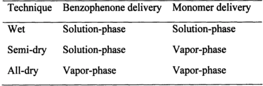
Grafting using BP has been investigated by a number of researchers.76 The
methods can be divided into three main categories shown in Table 1. The most
prominent is the all-solution-phase technique-both BP and the monomer are dissolved in a solution in which the surface to be grafted is immersed. This can also be performed by dipping the substrate in solutions of each material sequentially. '0,81 On the other hand, a BP-pretreated surface can be exposed to vaporized monomer to effect grafting. This pretreatment can be wet or dry. In the wet case, BP is dissolved in a solution (typically acetone) and cast onto the surface to be grafted. The surface is then dried to remove the solvent, leaving behind BP.8 2 The all-dry method exposes the to-be-grafted
surface to BP vapor, and the surface uptakes BP during the exposure. 81-" Although different, these three categories use the same Type-II behavior of BP under UV
irradiation-it abstracts labile hydrogen atoms from the surface to create chain-initiating radicals.
Table 1-1 Different Techniques of Using Benzophenone as a Photoinitiator
Technique Benzophenone delivery Monomer delivery
Wet Solution-phase Solution-phase
Semi-dry Solution-phase Vapor-phase
As with thin-film deposition, dry techniques such as chemical vapor deposition (CVD) are becoming increasingly prevalent due to their environmental benefits. The
success of all-dry CVD has been demonstrated by methods such as plasma-enhanced CVD (PECVD),86-88 hot-filament CVD (HFCVD),8 99' and initiated CVD (iCVD).4,7 2,92
A wide variety of polymeric and organosilicon materials have been made using these methods. iCVD, unlike PECVD and HFCVD, uses initiators to accelerate film growth and allow control of molecular weight and morphology, yet linear, well-defined chemical structures are produced.4 72'92 CVD is able to produce films of nanoscale thickness with
macroscale uniformity on complex geometries.93 The dryness of the process avoids the wetting and surface-tension effects associated with wet techniques, so surfaces with nano- or microscale topography can be coated uniformly. The added benefits of grafting motivate the investigation of an iCVD-like grafting process. The envisioned scheme combines the benefits of iCVD and grafting by exposing surfaces to vapors of a Type-IL photoinitiator, such as BP, and a monomer in a continuous or a semi-batch manner. Although all-dry vapor-phase photografting has been examined,83'84 there have been few
if any reports of one-step CVD-like grafting processes. The goal of this portion of the thesis is to use an existing CVD chamber to perform solventless grafting, hereby referred to as grafting CVD (gCVD).
1.4 Scope of Thesis
Chapter Two reports a combinatorial approach to iCVD. A five fold increase in research efficiency has been realized by simultaneously depositing films at five filament temperatures. The system was validated for use with both an acrylic and styrenic
monomer by comparing chemical structure, growth rates, and molecular weights with films deposited at the same conditions in a conventional reactor.
Chapter Three describes the use of the styrenic polymer characterized in Chapter Two for antimicrobial coating of finished textile substrates. The coatings were highly effective, killing about 6 log of both gram-negative and gram-positive bacteria.
Chapter Four examines a new method for covalently bonding polymer films deposited from the vapor phase known as grafting CVD, or gCVD. The new technique was used to deposit more durable antimicrobial coatings.
Appendices A, B, and C describe three additional projects, unrelated to
antimicrobial coatings, which are through the proof-of-concept stage and show promise for future work. These are iCVD of organic high-K dielectric films, grafted
superhydrophilic coatings and microfluidic channel coating.
Chapter Two through Four are structured as journal articles, and can thus be read as a self-contained work containing an abstract, introduction, experimental details, results and discussion, and relevant references. The Thesis concludes with a summary of work and suggestions for future work. Finally, the authors would like to thank the Institute for Soldier Nanotechnologies for funding.
1.5 References
1. Wang,
Q.
Thin Solid Films 2003, 430, (1-2), 78-82.2. Cassel, A. M.; Verma, S.; Delzeit, L.; Meyyappan, M.; Han, J. Langmuir 2001, 17, (2), 260-264.
3. Taylor, C. J.; Semancik, S. Chem. Mater. 2002, 14, (4), 1671-1673. 4. Mao, Y.; Gleason, K. K. Langmuir 2004, 20, (6), 2484-2488.
5. Smith, R. C.; Hoilien, N.; Roberts, J.; Campbell, S. A.; Gladfelter, W. L. Chem.
6. Smith, R. C.; Hoilien, I.; Chien, J.; Campbell, S. A.; Roberts, J. T.; Gladfelter, W.
L. Chem. Mater. 2003, 15, (1), 292-298.
7. Dagani, R. 2002, 80, (45), 58-60.
8. Senkan, S. Angew. Chem., Int. Ed. 2001, 40, (2), 312-329. 9. Hanak, J. J. J. Mater. Sci. 1970, 5, 964-971.
10. Takeuchi, I.; Newsam, J. M.; Wille, L. T.; Koinuma, H.; Amis, E. J. In
Combinatorial and Artifical Intelligence Methods in Materials Science, Combinatorial
and Artifical Intelligence Methods in Materials Science, Boston, MA, 2002, 2001; Materials Research Society: Boston, MA, 2001.
11. Cawse, J. N., Experimental Design for Combinatorial and High Throughput Materials Development. John Wiley & Sons: Hoboken, NJ, 2003; p 317.
12. Malhotra, R. In Combinatorial Materials Development, American Chemical Society Symposium Series, Washington, DC, 2002; American Chemical Society: Washington, DC, 2002; p 184.
13. Wang,
Q.;
Perkins, J.; Branz, H.; Alleman, J.; Duncan, C.; Ginley, D. Appl. SurfSci. 2002, 189, 271-276.
14. Wang,
Q.;
Yue, G.; Li, J.; Han, D. Solid State Commun. 2000, 113, 175-178. 15. Aiyer, H. N.; Nishioka, D.; Maruyama, R.; Shinno, H.; Matsuki, N.; Miyazaki, K.; Fujioka, H.; Koinuma, H. Jpn. J. Appl. Phys. 2001, 40, L81-L83.16. Cavicchi, R. E.; Semancik, S.; DiMeo, F.; Taylor, C. J. J Electroceram. 2003, 9, (3), 155-164.
17. Neely, A. N.; Maley, M. P. J. Clin. Microbiol. 2000, 38, (2), 724-726. 18. MacKinnon, M. M.; Allen, K. D. J. Hosp. Infect. 2000, 46, (3), 216-22 1. 19. Scudeller, L.; Leoncini, 0.; Boni, S.; Navarra, A.; Rezzani, A.; Verdirosi, S.; Maserati, R. J. Hosp. Infect. 2000, 46, (3), 222-229.
20. Klueh, U.; Wagner, V.; Kelly, S.; Johnson, A.; Bryers, J. D. J. Biomed Mater.
Res. 2000, 53, (6), 621-63 1.
21. Sun, Y.; Sun, G. J. Appl. Polym. Sci. 2003, 88, 1032-1039. 22. Borman, S. Chem. Eng. News 2002, 80, (22), 36-38.
23. Lin, J.; Qiu, S.; Lewis, K.; Klibanov, A. M. Biotechnol. Bioeng. 2002, 83, (2), 168-172.
24. El Ola, S. M. A.; Kotek, R.; White, W. C.; Reeve, J. A.; Hauser, P.; Kim, J. H.
Polymer 2004, 45, (10), 3215-3225.
25. Abel, T.; Cohen, J. I.; Engel, R.; Filshtinskaya, M.; Melkonian, A.; Melkonian, K.
Carbohydr. Res. 2002, 337, 2495-2499.
26. Sun, G.; Worley, S. D. J. Chem. Educ. 2005, 82, (1), 60-64.
27. Yuranova, T.; Rincon, A. G.; Bozzi, A.; Parra, S.; Pulgarin, C.; Albers, P.; Kiwi, J. J. Photochem. Photobiol. A-Chem. 2003, 161, (1), 27-34.
28. Tashiro, T. Macromol. Mater. Eng. 2001, 286, (2), 63-87.
29. Schreuder-Gibson, H. L.; Truong,
Q.;
Walker, J. E.; Owens, J. R.; Wander, J. D.; Jones, W. E. MRS Bull. 2003, 28, (8), 574-578.30. Raad, I.; Darouiche, R.; Dupuis, J.; AbiSaid, D.; Gabrielli, A.; Hachem, R.; Wall, M.; Harris, R.; Jones, J.; Buzaid, A.; Robertson, C.; Shenaq, S.; Curling, P.; Burke, T.; Ericsson, C.; Greenberg, S.; Hanania, N.; Yosher, D.; Gibson, D.; Reardon, M.; Reardon, P.; Darnule, T.; Mansouri, M.; Rolston, K.; Whimbey, E.; Bivins, C.; Huaringa, A.; Price, K.; Safar, H. Ann. Intern. Med. 1997, 127, (4), 267-&.
31. Maki, D. G.; Stolz, S. M.; Wheeler, S.; Mermel, L. A. Ann. Intern. Med. 1997, 127, (4), 257-&.
32. Gollwitzer, H.; Ibrahim, K.; Meyer, H.; Mittelmeier, W.; Busch, R.; Stemberger, A. J. Antimicrob. Chemother. 2003, 51, (3), 585-591.
33. Munson, E. L.; Heard, S. 0.; Doern, G. V. Chest 2004, 126, (5), 1628-1635. 34. Rupp, M. E.; Fitzgerald, T.; Marion, N.; Helget, V.; Puumala, S.; Anderson, J. R.; Fey, P. D. Am. J. Infect. Control 2004, 32, (8), 445-450.
35. Yue, I. C.; Poff, J.; Cortes, M. E.; Sinisterra, R. D.; Faris, C. B.; Hildgen, P.; Langer, R.; Shastri, V. P. Biomaterials 2004, 25, (17), 3743-3750.
36. Pacheco-Fowler, V.; Gaonkar, T.; Wyer, P. C.; Modak, S. J. Hosp. Infect. 2004, 57, (2), 170-174.
37. Rubinson, L.; Diette, G. B. J. Lab. Clin. Med. 2004, 143, (1), 5-13.
38. Hume, E. B. H.; Baveja, J.; Muir, B.; Schubert, T. L.; Kumar, N.; Kjelleberg, S.; Griesser, H. J.; Thissen, H.; Read, R.; Poole-Warren, L. A.; Schindhelm, K.; Willcox, M. D. P. Biomaterials 2004, 25, (20), 5023-5030.
39. Baveja, J. K.; Li, G.; Nordon, R. E.; Hume, E. B. H.; Kumar, N.; Willcox, M. D. P.; Poole-Warren, L. A. Biomaterials 2004, 25, (20), 5013-502 1.
40. Donlan, R. M.; Costerton, J. W. Clin. Microbiol. Rev. 2002, 15, (2), 167-193. 41. Thomas, J.; Choi, S. B.; Fjeldheim, R.; Boudjouk, P. Biofouling 2004, 20, (4-5), 227-236.
42. Hilal, N.; Al-Khatib, L.; Atkin, B. P.; Kochkodan, V.; Potapchenko, N.
Desalination 2003, 158, 65-72.
43. Tzoris, A.; Hall, E. A. H.; Besselink, G. A. J.; Bergveld, P. Anal. Lett. 2003, 36, (9), 1781-1803.
44. Kalyon, B. D.; Olgun, U. Am. J. Infect. Control 2001, 29, (2), 124-125. 45. Jiang, H.
Q.;
Manolache, S.; Wong, A. C. L.; Denes, F. S. J. Appl. Polym. Sci. 2004, 93, (3), 1411-1422.46. Chen, Y.; Worley, S. D.; Huang, T. S.; Weese, J.; Kim, J.; Wei, C. I.; Williams, J. F. J. Appl. Polym. Sci. 2004, 92, (1), 363-367.
47. Sun, Y.; Sun, G. Macromolecules 2002, 35, (23), 8909-8912.
48. Anguige, K.; King, J. R.; Ward, J. P.; Williams, P. Math. Biosci. 2004, 192, (1), 39-83.
49. Lin, J.; Tiller, J. C.; Lee, S. B.; Lewis, K.; Klibanov, A. M. Biotechnol. Lett. 2002, 24, 801-805.
50. Lin, J.; Qiu, S.; Lewis, K.; Klibanov, A. M. Biotechnol. Prog. 2002, 18, 1082-1086.
51. Lin, J.; Murthy, S. K.; Olsen, B. D.; Gleason, K. K.; Klibanov, A. M. Biotechnol.
Lett. 2003, 25, (19), 1661-1665.
52. Tiller, J. C.; Lee, S. B.; Lewis, K.; Klibanov, A. M. Biotechnol. Bioeng. 2002, 79, (4), 465-471.
53. Tiller, J. C.; Liao, C.-J.; Lewis, K.; Klibanov, A. M. Proc. Natl. Acad. Sci. U. S. A. 2001, 98, (11), 5981-5985.
54. Park, D.; Wang, J.; Klibanov, A. M. Biotechnol. Prog. 2006, 22, (2), 584-589. 55. Lee, S. B.; Koepsel, R. R.; Morley, S. W.; Matyjaszewski, K.; Sun, Y. J.; Russell, A. J. Biomacromolecules 2004, 5, (3), 877-882.
57. Irikura, H.; Hasegawa, Y.; Takahashi, Y. J. Photopolym Sci. Technol. 2003, 16, (2), 273-276.
58. Park, E. S.; Kim, H. K.; Shim, J. H.; Kim, M. N.; Yoon, J. S. J. Appl. Polym. Sci. 2004, 93, (2), 765-770.
59. Gelman, M.; Weisblum, B.; Lynn, D.; Gellman, S. Org. Lett. 2004, 6, (4), 557-560.
60. Hanna, H. A.; Raad, II; Hackett, B.; Wallace, S. K.; Price, K. J.; Coyle, D. E.; Parmley, C. L. Chest 2003, 124, (3), 1030-1038.
61. Levy, S. B.; Marshall, B. Nat. Med 2004, 10, (12), S122-S129.
62. Stephens, R.; Mythen, M.; Kallis, P.; Davies, D. W. L.; Egner, W.; Rickards, A.
Br. J. Anaesth. 2001, 87, (2), 306-308.
63. Chan, C. K.; Jarrett, F.; Moylan, J. A. J. Trauma-Injury Infect. Crit. Care 1976, 16, (5), 395-396.
64. Viala, J.; Simon, L.; Le Pommelet, C.; Philippon, L.; Devictor, D.; Huault, G.
Arch. Pediatr. 1997, 4, (11), 1103-1106.
65. Tozzi, P.; Al-Darweesh, A.; Vogt, P.; Stumpe, F. Eur. J. Cardio-Thorac. Surg. 2001, 19, (5), 729-731.
66. Silver, S.; Phung, L. T.; Silver, G. J. Ind Microbiol. Biotechnol. 2006, 33, (7), 627-634.
67. Silver, S. Fems Microbiol. Rev. 2003, 27, (2-3), 341-353.
68. Chen, Q. J.; Yang, J.; Lin, Z. D. Appl. Phys. Lett. 1995, 67, (13), 1853-1855. 69. Feenstra, K. F.; Schropp, R. E. I.; Van der Weg, W. F. J. Appl. Phys. 1999, 85, (9), 6843-6852.
70. Lau, K. K. S.; Caulfield, J. A.; Gleason, K. K. Chem. Mat. 2000, 12, (10), 3032-3037.
71. Lewis, H. G. P.; Caulfield, J. A.; Gleason, K. K. Langmuir 2001, 17, (24), 7652-7655.
72. Murthy, S. K.; Olsen, B. D.; Gleason, K. K. Langmuir 2002, 18, (16), 6424-6428. 73. Chan, K.; Gleason, K. K. Chem. Vapor Depos. 2005, 11, (10), 437-443.
74. Ma, M. L.; Mao, Y.; Gupta, M.; Gleason, K. K.; Rutledge, G. C. Macromolecules 2005, 38, (23), 9742-9748.
75. Chan, K.; Gleason, K. K. Langmuir 2005, 21, (19), 8930-8939.
76. Allen, N. S., Photopolymerisation and Photoimaging Science and Technology. Elsevier Applied Science: London, 1989.
77. Roffey, C. G., Photopolymerization ofSurface Coatings. Wiley: New York, 1982. 78. Belfield, K.; Crivello, J. V., Photoinitiated Polymerization. American Chemical
Society: Washington, DC, 2003.
79. Fouassier, J.-P., Photoinitiation, Photopolymerization, and Photocuring: Fundamentals and Applications. Hanser: Munich, 1995.
80. Ma, H. M.; Davis, R. H.; Bowman, C. N. Polymer 2001, 42, (20), 8333-8338. 81. Ma, H. M.; Davis, R. H.; Bowman, C. N. Macromolecules 2000, 33, (2), 331-335. 82. Ogiwara, Y.; Kanda, M.; Takumi, M.; Kubota, H. 1981, 19, (9), 457-462.
83. Howard, G. J.; Kim, S. R.; Peters, R. H. J Soc. Dyers Colour. 1969, 85, 468. 84. Seiber, R. P.; Needles, H. L. J. Appl. Polym. Sci. 1975, 19, (8), 2187-2206. 85. Wirsen, A.; Sun, H.; Albertsson, A. C. Biomacromolecules 2005, 6, (5), 2697-2702.
86. Hollahan, J. R.; Bell, A. T., Techniques and Applications of Plasma Chemistry. Wiley: New York, 1974.
87. Yasuda, H., Plasma Polymerization. Academic: Orlando, FL, 1985. 88. Inagaki, N., Plasma Surface Modification and Plasma Polymerization. Technomic: Lancaster, PA, 1996.
89. Lau, K. K. S.; Gleason, K. K. J. Fluor. Chem. 2000, 104, (1), 119-126.
90. Pryce Lewis, H. G.; Casserly, T. B.; Gleason, K. K. J. Electrochem. Soc. 2001, 148, (12), F212-F220.
91. Loo, L. S.; Gleason, K. K. Electrochem. Solid State Lett. 2001, 4, (11), G81 -G84. 92. Pryce Lewis, H. G.; Caulfield, J. A.; Gleason, K. K. Langmuir 2001, 17, (24), 7652-7655.
93. Pierson, H. 0., Handbook of Chemical Vapor Deposition. 2nd ed.; Noyes Publications: Norwich, NY, 1999.
Chapter Two
Combinatorial Initiated Chemical Vapor Deposition for Polymeric
Thin Films*
2.1 Abstract
A new combinatorial initiated chemical vapor deposition (iCVD) system was fabricated and used to efficiently determine the deposition kinetics for two new polymeric thin films, poly(diethylaminoethylacrylate) (PDEAEA) and
poly(dimethylaminomethylstyrene) (PDMAMS). The results of combinatorial
depositions were compared to blanket iCVD depositions at identical conditions using the appropriate vinyl monomer with tert-amylperoxide as the initiator. Fourier transform infrared spectroscopy (FTIR) reveals similar chemical structure in blanket and combinatorial films. FTIR also show that functional groups are retained in iCVD of PDMAMS, whereas essentially all fine chemical structure of the material is destroyed in plasma-enhanced CVD. The maximum observed growth rate of PDEAEA and
PDMAMS was 43 and 11 nm/min respectively. The activation energy of growth with respect to, filament temperature (Ea,fllament) was 88.4±1.6 kJ/mol for PDEAEA and 42.0±1.7 kJ/mol for PDMAMS. Activation energies for growth with respect to substrate temperature (Ea,substrate) were -59.5±2.7 kJ/mol for PDEADA and -82.7±2.6 kJ/mol for PDMAMS, with the negative values consistent with adsorption limited kinetics. The molecular weight of PDEAEA films ranged from 1 to 182 kDa as a function of substrate temperature. It was found that the combinatorial system in all cases provided agreement, within experimental certainty, with results of blanket iCVD depositions, thus validating the use of the combinatorial system for future iCVD studies.
2.2 Introduction
Hanak' was one of the first to propose and synthesize a combinatorial materials library in 1970. A system for sputtering binary and ternary targets was used to produce compositional gradient thin film libraries, and the strategy of using the line-of-site property of physical vapor deposition (PVD) processes for the production of compositional gradient libraries has since become common.2-4 Since that time,
techniques for rapidly examining large numbers of discreet compositions have become widely used,A for instance in the study of catalyst materials. However, in these combinatorial studies, the synthesis method differs substantially from that employed in manufacture. A closer match between research and potential production processes is desired.
Several strategies have been applied to CVD research. Sequential deposition of discreet samples through a physical mask/manipulation of the substrate6~10 provides some
gain in research efficiency. Parallel depositions provide larger gains in research
efficiency and have been reported for compositional spreads using a method analogous to Hanak's PVD technique. 11-13 Parallel depositions have also been reported where
substrate temperature has been discreetly14-16 or continuously17 varied, and for varying
gas-phase reactant concentrations.'8
Hot-filament CVD (HFCVD) has been used to deposit diamond,'9 amorphous
silicon,2 0
and polymer thin films.21 Initiated chemical vapor deposition (iCVD) is a subset of HFCVD in which a free radical initiator species is used to decrease the filament temperature and substantially enhance the deposition rate.26 The iCVD method has been previously used to deposit a range of functional polymers, including