Publisher’s version / Version de l'éditeur:
Vous avez des questions? Nous pouvons vous aider. Pour communiquer directement avec un auteur, consultez la première page de la revue dans laquelle son article a été publié afin de trouver ses coordonnées. Si vous n’arrivez pas à les repérer, communiquez avec nous à [email protected].
Questions? Contact the NRC Publications Archive team at
[email protected]. If you wish to email the authors directly, please see the first page of the publication for their contact information.
https://publications-cnrc.canada.ca/fra/droits
L’accès à ce site Web et l’utilisation de son contenu sont assujettis aux conditions présentées dans le site LISEZ CES CONDITIONS ATTENTIVEMENT AVANT D’UTILISER CE SITE WEB.
IEEE Vehicular Technology Conference [Proceedings], 2004
READ THESE TERMS AND CONDITIONS CAREFULLY BEFORE USING THIS WEBSITE. https://nrc-publications.canada.ca/eng/copyright
NRC Publications Archive Record / Notice des Archives des publications du CNRC :
https://nrc-publications.canada.ca/eng/view/object/?id=b5479011-8e3e-4592-87ac-a6ef38f73bf9
https://publications-cnrc.canada.ca/fra/voir/objet/?id=b5479011-8e3e-4592-87ac-a6ef38f73bf9
NRC Publications Archive
Archives des publications du CNRC
This publication could be one of several versions: author’s original, accepted manuscript or the publisher’s version. / La version de cette publication peut être l’une des suivantes : la version prépublication de l’auteur, la version acceptée du manuscrit ou la version de l’éditeur.
Access and use of this website and the material on it are subject to the Terms and Conditions set forth at
Underground Mine Wireless Propagation Modeling
National Research Council Canada Institute for Information Technology Conseil national de recherches Canada Institut de technologie de l'information
Underground Mine Wireless Propagation
Modeling *
Ndoh, M., and Delisle, G. Y.
September 2004
* published in the IEEE Vehicular Technology Conference. Los Angeles, California, USA. September 26-29, 2004. NRC 47457.
Copyright 2004 by
National Research Council of Canada
Permission is granted to quote short excerpts and to reproduce figures and tables from this report, provided that the source of such material is fully acknowledged.
Underground Mines Wireless Propagation
Modeling
Moïse Ndoh
Institute for Information Technology-Wireless Systems National Research Council
Sydney, Nova Scotia, Canada e-mail: [email protected]
Gilles Y. Delisle
School of Information Technology and Engineering, University of Ottawa
Ottawa, Canada, K1N 6N5 e-mail: [email protected]
Abstract—In view of an underground mines wireless LAN
networks implementation in a real gold mine in Val-d’Or, Northen Québec, C, propagation loss measurements were taken at 18 GHz. These results are reported and compared with a newly introduced method based on a cascade of impedances analogy. Significant statistical, analytical and numerical parameters for wireless communication such as rough sidewalls impedances, reflection coefficients, impulse response, fast fading and attenuation loss due to the direct and multipath components are reported and discussed.
Keywords-wireless propagation, channel modeling, mine
tunnel , mines galleries, wireless LAN communications, wireless networks, mining environments, complex confined media, wireless propagation modeling.
I. INTRODUCTION
Modern exploitation of mineral resources, particularly mines galleries, requires that cellular phones, high speed modems, remote control and video transmission be available anytime, anywhere. These wireless multimedia services will have to insure that the personnel can be localized anywhere and this remains an important challenge for telecommunication engineers and systems designers. Some studies on the propagation characteristics in underground environments, including the effect of obstacles, attenuation and multiple reflections are available [1-10]. To achieve these objectives, a new approach named cascade impedance method [11-12] is used to predict the propagation in a complex and diffracting rough mine.
II. MINES GALLERIES MODELING
In the case of a mine gallery, the problem faced is how to convey the electromagnetic waves radio from outdoor to the
indoor mine corridors. The proposed topology of the radio transmission links is shown in Figure 1.
In this figure, an external radio based station (EBS) and two transmitter and receiver antennas are shown. The outdoor part can be operated with the wireless LAN technologies similar to the case of rural, urban or forest environment. The second propagation link is concerned with the routing of the RF signal inside the mine tunnel. The signal is delivered to the underground access network after an initial portion of path in free space (see (1) in Fig.1), then to the underground base station (UBS) in the mine corridor through a coaxial or optical fiber link (see (2) in Fig.1).
The third part of the link, from the underground base station (UBS) to the mine corridors, is done through access points such as AP1, AP2 ( (3) in Figure 1) or in Figure 2 and Figure 3.
B. Reliable Mining Network
Figure 2 and Figure 3 represents the overview of the wireless communication system in CANMET mine laboratory 70 m level. This wireless LAN mine implementation uses many access points. Some of them are connected via a co-axial cable; some have the possibility to communicated point to point using RF. Some of these access points systems are located on sidewalls exhibiting very significant roughness. Very recent studies [11-12] have showed that, there are three propagation zones in mine segment and that, the normal distance between the accesses points for the reception of radio waves signal in rough mining tunnel appears to be of the order of 20-35 meters. Beyond this distance, it is expected that over 75% of the useful signals will be lost will be attenuated dielectric losses due to rough walls. The dimensions of the mine corridors are small and comparable to those of Pico cells, the segments are characterized by the several attenuations, strong multipath, fading and significant diffraction. The problem therefore consists in finding a way to model theoretically the radio propagation in such a mining environment. In the following, is introduced an original model based on an efficient use of the concept called the cascade impedances method (CIM).
Figure 1. Outdoor- Indoor mining wireless system implementation.
Figure 2. Typical view of the underground mining Wireless Network.
III. THE CASCADE IMPEDANCES METHOD (CIM)
The basic original idea comes from the fact that, in spite of the multiple reflection, diffraction and attenuation due to roughness and the complexity of the channel in a mining tunnel, it is still a transmission channel and consequently it can ultimately be considered as a transmission line. With this assumption, it is possible to statistically predict the roughness of the surface of the mining tunnel by assuming its behavior to be analogous to that of cascade dielectric impedances with loses. Many different cases of propagation in mining tunnels are therefore presented [12] to show how this technique can be practically implemented. First, our model validity is established by considering the classical smooth sidewalls case and then after, it is extended to the rough sidewalls tunnel cases [12].
To characterize the propagation in a non-canonical mining tunnel such the one illustrated in Figure 3, the cascade impedance method (CIM) is applied in combination with the statistical method segmental method (SSM) [12], means that the mining tunnel will divided into m segments (Figure 3, Figure 4). Each segment is subdivided in m sections (Fig.4) and each section has k cells in transversal and vertical direction.
Considering that the free space of a non canonical mining tunnel (Figure 4) can be modeled as the impedance
[
Z
o]
andthat the magnetic field in free space and inside the four rough dielectric walls are respectively [Hz(0)(x,y,z)],[H1(x,y,z)],
[H2(x,y,z)], [H3(x,y,z)], [H4(x,y,z)]. Using the CIM approach,
it can be represented using the models of Figure 5.
Figure 5. CIM model for the waveguide of Figure 4.
[Z1] [Z3] [Z o] [Z 2] [Z4]
[H
4(x,y,z)] [Hz(0) (x,y,z)][H
1(x,y,z)][H
3(x,y,z)][H
2(x,y,z)] zA. Analytical formulation
Using the CIM approach, the matrix of cascade impedances for all the mines with m sections can be expressed as:
[ ]
[ ]
( )[ ]
( )[ ]
( ) = ∗ m Z Z Z Z 1 2 1 1 1 1 # ,[ ]
[ ]
( )[ ]
( )[ ]
( ) = ∗ m Z Z Z Z 2 2 2 1 2 2 # (1)[ ]
[ ]
( )[ ]
( )[ ]
( ) = ∗ m Z Z Z Z 3 2 3 1 3 3 # ,[ ]
[ ]
( )[ ]
( )[ ]
( ) = ∗ m Z Z Z Z 4 2 4 1 4 4 # (2)The equivalent matrix of cascade impedances and reflection coefficients for each section (i) (Figure 4) are given by:
[ ]
Z
eq ( )i[ ]
Z
( )i[ ]
Z
( )i[ ]
Z
( )i[ ]
Z
* ( )i 4 * 3 * 2 * 1 *=
//
//
//
(3)[ ]
( )[ ]
( )[ ]
[ ]
( )[ ]
0 0 Z Z Z Z i eq i eq i eq + − = Γ (4)The magnetic field matrix for all the components of the section (i) ( Figure 4 ) in z direction is given by:
( )
(
)
[
]
( ) ( )(
)
( )(
)
( )(
)
( )(
)
( )(
)
( )(
)
( )(
)
( )(
)
( )(
)
( )(
)
( )(
)
( )(
)
= k k o z k o z k o z k o z o z o z k o z o z o z k o z o z o z i ik ik z b a H b a H b a H b a H b a H b a H b a H b a H b a H b a H b a H b a H b a H 1 1 1 12 1 11 13 1 13 12 13 11 12 1 12 12 12 11 11 1 11 12 11 11 0 , , , , , , , , , , , , , δ δ δ δ δ δ δ δ δ δ δ δ δ " # " # # " " " (5)The temporal magnetic field matrix for all the components of the section (i) ( Figure 4 ) is given by:
( )
(
)
[
]
( ) ( )(
)
( )(
)
( )(
)
( )(
)
( )(
)
( )(
)
( )(
)
( )(
)
( )(
)
( )(
)
( )(
)
( )(
)
= k k o t k o t k o tt k o t o t o t k o t o t o tt k o tt o t o t i ik ik t b a H b a H b a H b a H b a H b a H b a H b a H b a H b a H b a H b a H b a H 1 1 1 12 1 11 13 1 13 12 13 11 12 1 12 12 12 11 11 1 11 12 11 11 0 , , , , , , , , , , , , , δ δ δ δ δ δ δ δ δ δ δ δ δ " # " # # " " " (6)The electric field matrix for all the components of all the section (i) ( Figure 4 ) in z direction is given by:
[ ]
[
( )]
( )m [ ]( )m(
[
eq]
( )m)
z M m g H Z E =∑
⋅ ⋅ + + Γ = 1 1 0 0 1 δ (7)IV. Analytical results
Figure 6 and figure 7 illustrates respectively the variation of the simulated received power in a rough segment of mine as obtained using the proposed model at 18 GHz.
Figure 6. 2D predicted received signal at 18 GHz.
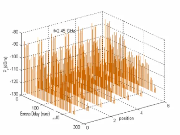
Figure 7. 3D predicted received signal at 18 GHz Figure 8 represents the 3 D variation of the simulated impulse response of the received power in a rough segment of mine using the proposed model at 2.45 GHz.
Figure 8. The simulated 3D impulse response of the received power at 2.45 GHz
Figure 9 is a comparison between measurements and simulation of the transmitted power in canonical mining segment at f=18 GHz. Several experimental measurements [13] have been conducted in different parts of this mine gallery located in the city of Val-d’Or, in Northern of Québec, Canada. The length of gallery is more than 900m, his width and the height are varying 2.8-4.8 m and 3-5 m. The temperature inside the mine is 5~6 degree. The dielectric sidewalls are very rough.
The results of Figure 6, Figure 7, Figure 8 and Figure 9 shown that, the radio waves propagation in this segment is characterized by the several attenuations. These attenuations are caused by strong multipath, fading and significant diffraction. More detailed analysis of the underground wireless implementation system, analytical and measurement results will be presented at the conference.
Figure 9. 2D. Measurements and simulation of the transmitted power in canonical mining segment, f=18 GHz.
V. CONCLUSION
The CIM model has been used to characterize the radio waves propagation in a mine with rough sidewalls. Efficiency and accuracy of the model has been tested and compared with several measurements taken in a real gold mine. The particular advantages of the suggested method is that, it can be used practicaly, analyticaly, statisticaly or numericaly to characterize the propagation in many types of environments. Comparativily with other methods with requires astronomical quantities of calculations for the real cases of installations with important sizes comparativily to wavelength, it has been prouved that, the CIM model has significant performance and precision using the mean characteristc values.
According to our analyses, we can confirm that, the realization of the wide band wireless networks in mines galleries is possible and a wireless LAN networks model has been proposed.
REFERENCES
[1] A.G.Emslie, R.L.Lagace and P.F.Strong, “Theory of Propagation of UHF Radiowaves in Coal Mine Tunnels,” in proc. ,Trough-the-Earth Electromagnetics Workshop, Colorado School of Mines, Golden, Colorado., Aug. 15-17, 1973.
[2] P.Delogne, “Basic Mechanisms of Tunnel Propagation ,” Radio Sci., vol. 11, pp.295-303, Jan-Feb 1976.
[3] S.F.Mahmoud, J.R.Wait, “Geometrical Optical Approach for Electromagnetic Propagation in Rectangular Mine Tunnels,” Radio.,
Sci., vol.9 no.12 pp.1147-1158, 1974.
[4] M.Liénard and P.Degauque, “Natural Wave Propagation in Mine Environments,”IEEE Trans.Antennas Propagat.,, vol.48, no.9, pp-1326-1339 Sept 2000.
[5] Y.P.Zhang, G.X.Zheng and J.H.Sheng, “Radio Propagation at 900 MHz in Underground Coal Mines,” IEEE Trans.Antennas and Propagat., vol. 49,no.5,pp.757-762, May 2001.
[6] M.Hämäläinen, J.Talvitie,V.Hovinen, P.Leppänen, “ Wideband Radio Channel Measurement in a Mine,” IEEE 5th Inter. Symp. On Spread
Spectrum Technics & Appl., ISSSTA’ 98. Sun City, South-Africa,
pp.522-526, Sept 2-4, 1998.
[7] L. Sydänheimo, M.keskilammi, M.kivikoski, “Reliable Mobile Computing to Underground Mine,” Inter. Conf. on Applied Informatics 2000 Innsbruck, Feb 2000.
[8] Y.Yamaguchi, T.Abe, and T.Sekiguchi, “ Propagation Characteristics of the dominant mode in tunnels,” Trans.IECE Japan, vol. J65-B, no.4, pp, 471 - 476, Apr.1982.
[9] Y.Hwang, Y.P.Zhang and R.G. Kouyoumjian, “Ray-Optical Prediction of Radio-Wave Propagation Characteristics in Tunnel Environment Part 2: Analysis and Measurements”, IEEE Trans., Antennas Propagat.,vol.46, no.9, pp.1337-1345 Sept 1998.
[10] D.Didaskalou,T.M.Schäfer,“Ray-Density Normalization for Ray-Optical Wave Propagation Modeling in Arbi- trarily Shaped Tunnel,” IEEE Trans.Antennas and Propagat., vol.48 no.9, pp.1316-1325, Sept.2000. [11] M.Ndoh, G.Y.Delisle and R.Le “A novel approach to propagation
prediction in a confined rough surfaces”, The International Journal of Numerical Modelling, Electronical Network, Devices and Fields. JNM:521, vo.16, pp.535-555, Dec. 2003.
[12] M. Ndoh, “Modélisation de la propagation des ondes électromagnétiques dans un environnement minier”, thèse de Ph.D., Département de génie électrique et génie informatique, Université de Laval, Québec, Canada, 27 avril 2004.
[13] M.Djadel., C.Despins, S.Affès “Narrowband Propagation Characteristics at 2.45 and 18GHz in Underground Mining’’, IEEE GLOBECOM