HAL Id: hal-02884319
https://hal.archives-ouvertes.fr/hal-02884319
Submitted on 17 Dec 2020HAL is a multi-disciplinary open access archive for the deposit and dissemination of sci-entific research documents, whether they are pub-lished or not. The documents may come from teaching and research institutions in France or abroad, or from public or private research centers.
L’archive ouverte pluridisciplinaire HAL, est destinée au dépôt et à la diffusion de documents scientifiques de niveau recherche, publiés ou non, émanant des établissements d’enseignement et de recherche français ou étrangers, des laboratoires publics ou privés.
The geology and geophysics of Kuiper Belt object
(486958) Arrokoth
J. Spencer, S. Stern, J. Moore, H. Weaver, K. Singer, C. Olkin, A. Verbiscer,
W. Mckinnon, J. Wm. Parker, R. Beyer, et al.
To cite this version:
J. Spencer, S. Stern, J. Moore, H. Weaver, K. Singer, et al.. The geology and geophysics of Kuiper Belt object (486958) Arrokoth. Science, American Association for the Advancement of Science, 2020, 367 (6481), pp.eaay3999. �10.1126/science.aay3999�. �hal-02884319�
1
The Geology and Geophysics of Kuiper Belt Object
(486958) Arrokoth
This is the author's version of the work. It is posted here by permission of the AAAS for personal use, not for redistribution. The definitive version was published in Science , (2020-02-13). DOI:
https://doi.org/10.1126/science.aay3999
J.R. Spencer1*, S.A. Stern1, J.M Moore2, H.A. Weaver3, K.N. Singer1, C.B Olkin1, A.J.
Verbiscer4, W.B. McKinnon5, J.Wm. Parker1, R.A. Beyer6,2, J.T. Keane7, T.R. Lauer8, S.B.
Porter1, O.L. White6,2, B.J. Buratti9, M.R. El-Maarry10,11, C.M. Lisse3, A.H. Parker1, H.B.
Throop12, S.J. Robbins1, O.M. Umurhan2, R.P. Binzel13, D.T. Britt14, M.W. Buie1, A.F. Cheng3,
D.P. Cruikshank2, H.A. Elliott15, G.R. Gladstone15, W.M. Grundy16,17, M.E. Hill3, M. Horanyi18,
D.E. Jennings19, J.J. Kavelaars20, I.R. Linscott21, D.J. McComas22, R.L. McNutt Jr.3, S.
Protopapa1, D.C. Reuter19, P.M. Schenk23, M.R. Showalter6, L.A. Young1, A.M. Zangari1, A.Y.
Abedin20, C.B. Beddingfield6, S.D. Benecchi24, E. Bernardoni18, C.J. Bierson25, D. Borncamp26,
V.J. Bray27, A.L. Chaikin28, R.D. Dhingra29, C. Fuentes30, T. Fuse31, P.L Gay24, S.D.J. Gwyn20,
D.P. Hamilton32, J.D. Hofgartner9, M.J. Holman33, A.D. Howard34, C.J.A. Howett1, H. Karoji35,
D.E. Kaufmann1, M. Kinczyk36, B.H. May37, M. Mountain38, M. Pätzold39, J.M. Petit40, M.R.
Piquette18, I.N. Reid41, H.J. Reitsema42, K.D. Runyon3, S.S. Sheppard43, J.A. Stansberry41, T.
Stryk44, P. Tanga45, D.J. Tholen46, D.E. Trilling17, L.H. Wasserman16 1 Southwest Research Institute, Boulder, CO 80302, USA
2 NASA Ames Research Center, Moffett Field, CA 94035-1000, USA
3 Johns Hopkins University Applied Physics Laboratory, Laurel, MD 20723, USA 4 Department of Astronomy, University of Virginia, Charlottesville, VA 22904, USA
5 Department of Earth and Planetary Sciences and McDonnell Center for the Space Sciences,
Washington University, St. Louis, MO 63130, USA
6 SETI Institute, Mountain View, CA 94043, USA
7 Division of Geological and Planetary Sciences, California Institute of Technology, Pasadena,
CA 91125, USA
8 National Science Foundation’s National Optical Infrared Astronomy Research Laboratory,
Tucson, AZ 26732, USA
9 Jet Propulsion Laboratory, California Institute of Technology Pasadena, CA 91109, USA 10 Department of Earth and Planetary Sciences, Birkbeck, University of London WC1E 7HX,
London, UK
11University College London, Gower St, Bloomsbury, London WC1E 6BT, United Kingdom 12 Independent Consultant, Washington, D.C., USA
13 Massachusetts Institute of Technology, Cambridge, MA 02139, USA
14 Department of Physics, University of Central Florida, Orlando, FL 32816, USA 15 Southwest Research Institute, San Antonio, TX 78238, USA
16 Lowell Observatory, Flagstaff, AZ 86001, USA
17 Department of Astronomy and Planetary Science, Northern Arizona University, Flagstaff, AZ,
86011, USA
18 Laboratory for Atmospheric and Space Physics, University of Colorado, Boulder, CO 80303,
2
19 NASA Goddard Space Flight Center, Greenbelt, MD 20771, USA 20 National Research Council of Canada, Victoria, BC V9E 2E7, Canada 21 Independent Consultant, Mountain View, CA 94043, USA
22 Department of Astrophysical Sciences, Princeton University, Princeton, NJ 08544, USA 23 Lunar and Planetary Institute, Houston, TX 77058, USA
24 Planetary Science Institute, Tucson, AZ 85719, USA
25 Earth and Planetary Science Department, University of California, Santa Cruz, CA 95064,
USA
26 Decipher Technology Studios, Alexandria, VA 22314
27 Lunar and Planetary Laboratory, University of Arizona, Tucson, AZ 85721, USA 28 Independent Science Writer, Arlington, VT 05250, USA
29 University of Idaho, Moscow, ID 83844, USA
30 Universidad de Chile, Centro de Astrofísica y Tecnologías Afines, Santiago, Chile
31 Kashima Space Technology Center, National Institute of Information and Communications
Technology, Kashima, Ibaraki 314-8501, Japan
32 Department of Astronomy, University of Maryland, College Park, MD 20742, USA 33 Center for Astrophysics, Harvard-Smithsonian Center for Astrophysics, Cambridge, MA
02138, USA
34 Department of Environmental Sciences, University of Virginia, Charlottesville, VA 22904,
USA+D132
35 National Institutes of Natural Sciences, Tokyo, Japan
36 Marine, Earth, and Atmospheric Sciences, North Carolina State University, Raleigh, NC
27695, USA
37 Independent Collaborator, Windlesham, England, GU20 6YW, UK
38 Association of Universities for Research in Astronomy, Washington, DC 20004, USA 39 Rheinisches Institut für Umweltforschung an der Universität zu Köln, Cologne 50931,
Germany
40 Institut Univers, Temps-fréquence, Interfaces, Nanostructures, Atmosphère et environnement,
Molécules, Unité Mixte de Recherche, Centre National de la Recherche Scientifique, Universite Bourgogne Franche Comte, F-25000 Besancon, France
41 Space Telescope Science Institute, Baltimore, MD 21218, USA 42 Independent Consultant, Holland, MI 49424, USA
43 Department of Terrestrial Magnetism, Carnegie Institution for Science, Washington, DC
20015, USA
44 Roane State Community College, Oak Ridge, TN 37830, USA
45 Université Côte d'Azur, Observatoire de la Côte d’Azur, Laboratoire Lagrange/ Centre
National de la Recherche Scientifique, Unité Mixte de Recherche 7293, 06304 Nice Cedex 4, France
46 Institute for Astronomy, University of Hawaii, Honolulu, HI 96822, USA
3
The Cold Classical Kuiper Belt, a class of small bodies in undisturbed orbits beyond Neptune, are primitive objects preserving information about Solar System formation. The New Horizons spacecraft flew past one of these objects, the 36 km long contact binary (486958) Arrokoth (2014 MU69), in January 2019. Images from the flyby show that Arrokoth has no detectable rings, and no satellites (larger than 180 meters diameter) within a radius of 8000 km, and has a lightly-cratered smooth surface with complex geological features, unlike those on previously visited Solar System bodies. The density of impact craters indicates the surface dates from the formation of the Solar System. The two lobes of the contact binary have closely aligned poles and equators, constraining their accretion mechanism.
On 2019 January 1 at 05:33:22 Universal Time (UT) the New Horizons spacecraft flew past the Kuiper Belt object (KBO) (486958) Arrokoth (2014 MU69, originally nicknamed “Ultima
Thule”), at a distance of 3538 km (1). Arrokoth is a contact binary consisting of two distinct lobes, connected by a narrow neck. Based on its orbital semi-major axis, low eccentricity and inclination (2), and its albedo and color (1,3), Arrokoth is classified as a member of the dynamically cold, non-resonant “cold classical” KBO (CCKBO) population, and probably a member of the tight orbital clustering of CCKBOs known as the kernel (4). There is no known mechanism for transporting the majority of these objects onto these nearly circular orbits, so they are thought to have formed in situ and remained dynamically undisturbed since the formation of the Solar System. Due to the low impact rates (5) and low temperatures in the Kuiper Belt, CCKBOs are also thought to be physically primitive bodies. Arrokoth’s equivalent spherical diameter of 18 km (see below), makes it about 8.5 times smaller in diameter than a known break in the size-frequency distribution of CCKBOs at diameter ~100 km (6).
Initial results from this flyby (1) were based on early data downlinked from the spacecraft. Since then, additional data have been downlinked, including: (i) the highest-resolution images from the flyby, taken with the narrow-angle Long-Range Reconnaissance Imager (LORRI) camera (7). These LORRI images have a pixel scale which is 4 times finer (33 m pixel-1) than the 130 m
pixel-1 of previously-available Multicolor Visible Imaging Camera (MVIC) (8) images (1),
though due to smear and a lower signal-to-noise ratio (SNR), the effective resolution of the LORRI images is only about 2 times better than the MVIC images; (ii) Additional LORRI images from earlier approach epochs, with higher SNR than previously-downlinked data; (iii) Improved LORRI distant approach rotational coverage, constraining the shape and rotational parameters; and (iv) Additional satellite and ring search data from LORRI and MVIC. See (9) for image processing details. We describe Arrokoth’s shape, geological evolution, and satellite and ring constraints resulting from these additional data, and from continued analysis of all downlinked data.
Stereo Imaging
A pair of LORRI images designated CA04 and CA06 (Fig. 1A, Table S1 (9)) provides improved stereo imaging to constrain the shape and topography of the close approach hemispheres of the two lobes. A stereographic terrain model derived from these images, (Data S1, (9)), is shown in Fig. 2. Topographic relief in the stereo model is ~0.5 km or less on both lobes (away from the neck region), similar to the 1.0 km and 0.5 km relief seen in limb profiles of the large and small lobes respectively (1). The stereo images (Fig. 1A) show additional topographic detail that is
4
visible by eye but is below the 200 meter vertical resolution of the terrain model. Our interpretation is based on both the terrain model and subjective analysis of the stereo pair.
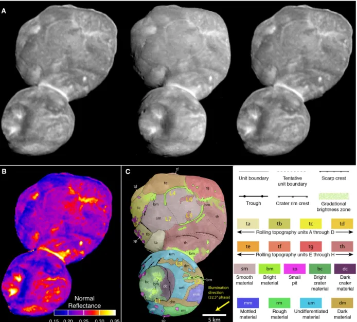
Fig. 1. Mapping of Arrokoth. A. Cross-eyed (left+center) and direct (center+right) stereo pair image of Arrokoth, taken by LORRI. The left and right images are CA04, range = 27,860 km, phase = 12.9°, 138 m pixel-1, while the center image is CA06, range = 6,650 km, phase = 32.5°, 33 m pixel-1. Both images have been deconvolved to remove the LORRI point-spread function, and motion blur from CA06, to maximize detail (9). B. 0.6 µm normal reflectance map of Arrokoth, based on image CA04. C.
Geomorphological map of Arrokoth, overlain on the deconvolved CA06 image. The positive spin axis of Arrokoth is pointing approximately into the page. Yellow labels L1 – L7 identify locations mentioned in the text. Geological units are labelled and colored as shown in the legend.
Rotation and Global Shape Modeling
No periodic brightness variation due to rotation was detected in Hubble Space Telescope (HST) photometry before the flyby, with an upper limit amplitude of about 0.15 magnitudes (10). Stellar occultations in July 2017 and August 2018 showed that Arrokoth had an elongated, possibly contact-binary shape (11). The elongated shape and the low lightcurve amplitude
5
implied that Arrokoth’s rotational pole was roughly aligned with the direction of the Sun and Earth.
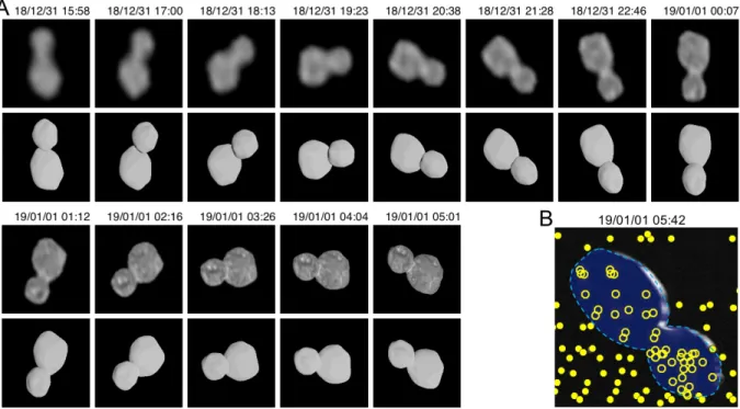
Arrokoth’s rotation and global shape are mostly determined from LORRI images taken between 2.2 days before the encounter, when Arrokoth first exceeded 2 pixels in length, and 9 minutes after encounter, when Arrokoth was last imaged (at high phase angle) as a receding crescent (Fig. 3). Disk-integrated photometry from earlier unresolved LORRI images showed no periodic variations in brightness, with an upper limit amplitude of 0.1 magnitudes (12), but were affected by confusion from the dense stellar background. The strongest constraints on the shape model are from a series of approach images with cadence between 1 hour and 20 minutes, starting 13.6 hours before closest approach, when Arrokoth subtended 10 pixels in length (Fig. 4A). These images covered 85% of the 15.92-hour rotation period, though only one hemisphere of Arrokoth was visible because of the near-alignment of the rotational pole with both the direction of the Sun and New Horizons’ approach direction.
Incorporating the additional rotational coverage images now available into the same rotational modelling techniques as before (1), the rotational period of Arrokoth is unchanged at 15.92 ± 0.02 hours, but its pole orientation has been refined. The positive rotational pole points to Right Ascension 317.5 ± 1°, Declination -24.9 ± 1° in the J2000 equinox. The rotation rate is within the range of other CCKBOs (13,14,15). The resulting obliquity of Arrokoth’s pole to its orbit is 99 ± 1°, and the rotational pole is 39 ± 1° from the New Horizons approach vector and 28 ± 1° from the direction from the Sun to Arrokoth during the encounter. The rotational brightness
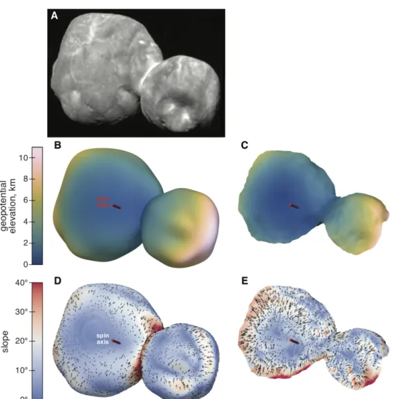
Fig. 2. Stereo and global shape models. A – C:
Comparison of the stereo shape model of the encounter face (top of each panel) to the global shape model (bottom of each panel), as seen from the -X (small lobe) direction (A), the +Y direction (B), and the south polar (-Z) direction (C). The red arrow shows the orientation and location of the positive spin axis. Each model is colored to show the variation in geopotential across the surface. The stereo model has been trimmed to remove edge effects. D: Stereo model seen from the same geometry as the CA06 observation (Fig. 1A, center), but with different lighting, chosen to highlight the small-scale topography.
6
variation implied by the shape model would have a peak-to-peak amplitude of 0.05 magnitudes from New Horizons’ approach direction, consistent with the earlier non-detections.
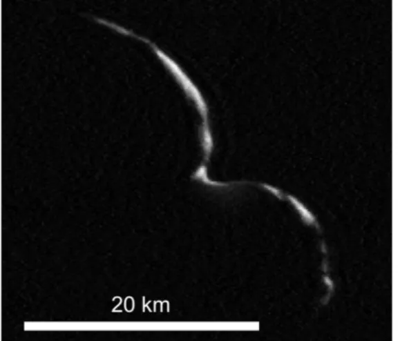
A low-resolution global shape model (Data S2 (9)) was produced using all available observations—even the early, distant ones—to refine the model. The high phase angle CA07 observation (Fig. 3, Table S1, (9)), of the illuminated double-crescent of Arrokoth, provides a constraint on how thick the unilluminated side can be, based on which stars are and are not eclipsed by the object (Fig. 4B). There remain differences between the shape model and the LORRI images in Fig. 4A, e.g. compared to the model, the images show a less indented neck and flatter outer end of the small lobe between December 31 20:38 and January 1 01:12.
The best-fitting global shape model consists of two roughly ellipsoidal lobes with overall dimensions X, Y, and Z of 36 × 20 × 10 km. Maximum dimensions of the large and small lobes are 20.6 × 19.9 × 9.4 km and 15.4 × 13.8 × 9.8 km respectively. The uncertainty for these dimensions is roughly 0.5 × 0.5 × 2.0 km in X, Y, and Z respectively; larger in the Z direction because the flyby imaged little of the +Z (northern) half of the object. The total volume is 3210 ± 650 km3,
equivalent to a sphere of diameter 18.3 ± 1.2 km. This volume is 30% larger than the previous estimate of 2450 ± 720 km3 (1), though consistent within the uncertainties. The larger lobe has a
volume equal to a sphere of diameter 15.9 ± 1.0 km, while the equivalent diameter for the smaller lobe is 12.9 ± 0.8 km. These values give a volume ratio (and mass ratio if densities are equal) of 1.9 ± 0.5.
Fig. 2 compares the global shape model to the stereo model of the encounter (-Z) side of
Arrokoth. There is broad agreement between the two techniques, though the south polar region of the large lobe is flatter in the stereo model, and the neck is smoother (a slope discontinuity at the neck is an intrinsic feature of the global shape model, due to its dual-lobe nature). We regard the stereo model as more reliable than the global shape model in the south polar and neck
regions, because the stereo model incorporates additional information due to the matching of albedo features, and because these albedo features can also produce artifacts in the global shape model, which assumes a uniform surface albedo. However, near the limbs the stereo model performs poorly because foreshortening makes feature matching difficult, while the global shape model is well constrained near the limbs.
Gravity Modeling
The irregular shape of Arrokoth produces a complex geophysical environment. We calculated Arrokoth’s geopotential (the sum of the gravitational and rotational potentials in a body-fixed reference frame) using the low-resolution global shape model, the 15.92-hour rotation period, and an assumed bulk density. In the absence of spacecraft gravity measurements or detected satellites, the density of Arrokoth is not directly constrained. However, if the neck of Arrokoth
Fig. 3. Arrokoth seen at high phase. New Horizons’ last view of Arrokoth (CA07), taken with the LORRI camera 9.4 minutes after closest approach at phase angle 152º, range 8,800 km, and resolution 175 m pixel-1. This image has been deconvolved to remove the motion smear visible in Fig. 4B (9). The large lobe is in the upper left and the small lobe is in the lower right.
7
is assumed to have no tensile strength, the density must be >290 kg m-3, or the rotation would
overcome the mutual gravity of the two lobes, causing them to separate. We assume a nominal bulk density of 500 kg m-3, similar to the measured densities of cometary nuclei (e.g. comet
67P/Churyumov-Gerasimenko (16)), which leads to a mean surface gravity of ~1 mm s-2. If this
density is correct, the requirement for the two lobes to support each other against their mutual gravity over their ~28 km2 contact area, implies a compressive strength (accounting for
centrifugal force) of > 2.3 kPa.
Figure 2 uses color to show the geopotential altitude, calculated by dividing the geopotential by the total acceleration, which represents elevation with respect to a gravitational equipotential surface (17). The geopotential is calculated from the global shape model, then evaluated on the surfaces of the global shape model and the stereo model (with positions matched to the global shape model (9)). This approach results in slight inaccuracies in the geopotential calculated across the stereo model, as there are regions where the stereo model rises above/below the surface of the global shape model. We focus on general trends that are robust to the uncertainties in the shape model. The geopotential is highest at the distal ends and equator, and decreases with increasing latitude on each lobe, reaching a global minimum at the neck. For an assumed density of 500 kg m-3, surface slopes (derivatives of the geopotential (17)) are generally gentle
(<20°) and slope downward to higher latitudes and into the neck region (Fig. S1). If material can flow downslope, then it will collect at higher latitudes and in the neck region. The stereo model shows that the neck is relatively smooth compared to its sharp appearance in the global shape
Fig. 4. Shape model compared to LORRI images. A: Deconvolved LORRI approach images of Arrokoth, compared to synthetic images with the same geometry derived from the global shape model. Images have been scaled to a constant frame size of 44 x 44 km, so become sharper as time progresses and range decreases. Celestial north is up. B: the CA07 departure image, with the silhouette (dark blue) and outline (light blue dashed line) of the shape model superposed. Open and filled yellow dots indicate the locations of occulted and unocculted stars respectively in the 6-frame CA07 sequence, used to constrain the shape of the unilluminated hemisphere.
8
model, with shallow slopes. The global shape model shows slopes of >30° at the neck, but this steepness is in part an artifact of the global model’s treatment of Arrokoth as two separate overlapping bodies.
The configuration of the two lobes of Arrokoth has implications for its formation and evolution (1,18). Using the same assumptions as above, we calculate the principal axes of inertia for the two lobes by slicing Arrokoth’s neck at the narrowest point. This confirms that the large lobe’s highest moment of inertia axis is aligned within < 5º of its small lobe counterpart, and the equatorial planes of the two bodies are also almost coincident in space, with the estimated center of mass of the small lobe displaced only 0.2 km from the equatorial plane of the large lobe.
Surface Units
Fig. 1B shows a map of 0.6 µm normal reflectance (19). The map is derived from the high-SNR CA04 image, using a merger of the global and stereo shape models to determine illumination at each point, and an assumed lunar-like photometric function which has no limb darkening at zero phase (20). The normal reflectance is equal to the geometric albedo of a body covered in
material with that location’s photometric properties. Arrokoth’s mean 0.6 µm normal reflectance, and thus its geometric albedo, is 0.23. The mean and standard deviation of the normal reflectance are 0.230 and 0.035 respectively for the large lobe, and 0.228 and 0.043 respectively for the small lobe.
We have also produced (9) an updated geological unit map of Arrokoth (Fig. 1C) that
supersedes the previous preliminary map (1). Note that this mapping is physiographic in nature and is not intended to rigorously convey stratigraphic relations between units. The small and large lobes have distinctly different surface appearances, so we mapped their surface units separately and describe them separately below.
Small Lobe: This lobe is dominated by a large depression (informally named Maryland), which
is very likely to be an impact crater (1). The projected crater rim measures ~6.7 by 6 km across in the image plane, with its longer axis roughly aligned with the principal axis of Arrokoth. The ellipticity might be due to foreshortening, in which case Maryland could be circular with
diameter 6.7 km. Stereo measurements show that the deepest well-determined point in Maryland is 0.51 km below a plane defined by the rim, or 1.3 km below the surface of a sphere with the small lobe’s mean radius, giving a depth/diameter ratio of 0.08 – 0.19. This depth/diameter ratio is similar to craters on other bodies with gravities similar to Arrokoth’s ~1 mm s-2, including
asteroids Šteins (~0.12, 0.8-1.3 mm s-2, (21)) and Eros (~0.13, 2.4-5.5 mm s-2, (22)), though
these bodies are composed of different materials and may have different porosities. Stereo imaging (Fig. 1A) reveals that the part of its rim furthest from the large lobe features a
promontory protruding into the crater (marked L1 in Fig 1C), at an elevation similar to the rest of the rim, which is not a common feature of impact crater rims.
Albedo patterns across the small lobe are complex. There are two patches of bright material (unit bm) within Maryland, which show discrete boundaries near the crater bottom, and fade towards the crater rim. Straddling the Maryland rim on the side opposite the bright patches is discrete, dark crater rim material (unit dc), which contrasts with the brighter terrain (unit bc) that forms the remainder of the crater interior. Elsewhere on the small lobe, discrete morphological units have albedo variations of almost a factor of two (Fig. 1B). The rough terrain at the distal end of the small lobe (unit rm), forms a facet that is relatively flat compared to the overall curvature of the surface, and is brighter than its immediate surroundings. The low illumination
9
angle on this facet reveals a rough surface texture at a scale of a few hundred meters, apparently mostly composed of sub-km pits, with one prominent ~150 m diameter pit (marked 27 in Fig. 6A) which resembles a small, fresh, bowl-shaped impact crater. Another nearby mottled bright unit (mm), may be similar, but is seen at a higher illumination angle so topographic roughness is not apparent, and has a distinctly crenulated and angular margin relative to that of unit rm (L2 in Fig. 1C).
Dark material surrounding the mm unit seems to be part of a discrete unit, designated dm, that wraps around much of the remainder of the observable surface of the small lobe - this material is the darkest on Arrokoth, with minimum 0.6 µm reflectance of 0.18. In places (L3 in Fig. 1C), it has a boundary with pointed and angular protrusions and rounded indentations, which may indicate material erosion and removal due to scarp retreat (1). Near L3 in Fig. 1C, there are also bright circular patches within the dark material. Running down the center of the principal mapped outcrop of dark material is a sinuous unit of bright material (unit bm), which stereo observations show occupies a V-shaped trough. The rest of the surface of the small lobe is nondescript at the available lighting and resolution and has been mapped as undifferentiated material (unit um). Crossing the undifferentiated material near the terminator between Maryland and the large lobe are a series of roughly parallel troughs, which are reminiscent of structural troughs seen on other similar-sized bodies, for instance asteroid Eros (23,24), Saturn satellites Epimetheus and Pandora (25), and the Martian satellite Phobos (26).
Our data confirm that the bright “neck” region connecting the two lobes has a diffuse margin at least on the large lobe side, but extreme foreshortening makes it difficult to characterize its margin on the small lobe side.
Large Lobe: The larger lobe is very different in appearance from the small lobe. Previous
analysis (1) mapped the large lobe as composed of a series of roughly equally-sized, discretely bounded, rolling topographic units. We interpret some of these units and their boundaries differently, though confirm the discrete nature of many of the units (ta through tg). Those near the terminator, ta – td, are distinctive, being brighter than adjacent units (Fig. 1B) (though ta is noticeably less red than the others (3)), and are clearly separated from the rest of the large lobe by a common, continuous scarp or trough and chain of pits. Units tg and th appear more mottled than adjacent units, and stereo imaging of these suggests that their surface consists of dark ridges and hills surrounded by brighter low terrain.
The rest of the large lobe is occupied by smooth material (unit sm) of moderate albedo, transected by a series of distinctive bright linear features (unit bm), some of which form an incomplete annulus. In some areas (e.g., L4 in Fig. 1C) the inner margin of the annulus appears sharply bounded, possibly with an outward-facing scarp, while the outer margin is more diffuse. Stereo observations (Figs. 1A, 2D) show that terrain within the annulus is flatter than the
undulating surface of the rest of the visible portion of the large lobe, and suggest that the annulus occupies a shallow trough. At the boundary between units tg and sm, the annulus appears to be interrupted by diffuse bright material, which may be superimposed upon it. In two places, L5 and L6 in Fig 1C, dark hills appear to extend into the sm unit. At L5 in Fig. 1C, these hills seem to be an extension, cut by the bm annulus, of similar hills on unit th. We discuss the possible origin of these features below.
Geological Interpretation
10
preferentially in depressions. The brightest material on the large lobe (the possible crater numbered 17 in Fig 6A), on the small lobe (bright features 42 and 43 in Fig. 6A), and in the bright collar between the two lobes all have normal 0.6 µm reflectance values near 0.37, suggesting that the bright material has similar chemical and physical properties in all these regions. The most extensive bright region, the bright collar in the topographic low of the “neck” region, may be simply the largest-scale example of a general process that creates bright low-lying material across Arrokoth. As
proposed in (1), loose, poorly consolidated, likely fine-grained bright material may move downslope and accumulate in depressions, which would imply that bright material is more mobile than dark material on Arrokoth. The complex albedo patterns on the small lobe, and their crenulated margins, may result from the exposure and differential erosion of multiple lighter and darker layers oriented roughly parallel to its surface, though independent topographic information is of insufficient quality to confirm this explanation.
It was previously proposed (1) that the large lobe might be composed of smaller sub-units that accreted separately. However, the improved imagery and topography raise issues with this interpretation. Firstly, the central bm annulus, enclosing what was mapped as a discrete sub-unit in (1) appears to be younger than some other surface features, and not an unmodified primordial boundary, for the following reasons: (i) the annulus is incomplete, with no discernable topographic feature or textural change in the gap region where it is missing (L7 in Fig 1C)- for this reason we map a
continuous unit, sm, across this gap; (ii) even where the annulus is conspicuous, it cuts across flat terrain for most of its length; and (iii) dark hills found on the th and sm sub-units appear to form a continuous physiographic unit cut by the annulus (at L5 in Fig 1C), and (iv) the partially concentric nature of the annulus suggests a structural basis, not greatly obscured by subsequent deposition. Secondly, though other proposed sub-units are distinguishable by differing surface textures, albedos and modest topographic inflections or other surface features, the overall shape of the large lobe is smooth and undulating. There are no major topographic
discontinuities between the sub-units comparable to that between the two lobes, as would be expected if the sub-units had similar internal strength to the lobes as a whole. Erosion and alteration over the past 4.5 Ga (see below) is likely to have modified the optical surface and the uppermost few Fig. 5. Possible explanations
for the appearance of the boundaries between terrain sub-units on the large lobe. The original surface (shown in red) is modified by the
processes labelled in each panel. We consider options D and E to be most consistent with the available evidence; see text for discussion.
11
meters (27) but probably does not explain the smoothness seen at the > 30 meter scale of the New Horizons imaging resolution.
Some possible explanations for the appearance of the annulus and other sub-unit boundaries are illustrated in Fig. 5. The sub-units may have been soft enough at the time of merger that they conformed to each other’s shapes on contact (28, 29,1) (Fig 5A), though no evidence for impact deformation is seen. In order for such deformation to take place at the time, the shear strength of the merging components must have been no more than 2 kPa, the ram pressure of an impacting body assuming a merger velocity of 1-2 m s-1 and a material density of 500 kg m-3. The
possibility that sub-units flowed viscously due to gravity after contact while still soft (Fig. 5B) can be discounted, because such flow would require an implausibly low shear strength of ~100 Pa. Erosion and downslope movement (mass wasting) may have filled in original gaps between the sub-units (Fig. 5C), though there is an absence of obvious boundaries (except perhaps at the the tg/sm contact) between material transported by mass wasting and in-situ material. The fact that mass wasting has not filled the much larger depression between the two lobes also implies that any major mass wasting process must have ceased before the merger of the two lobes. The original discontinuities may have been buried by subsequent accretion or redistribution of surface material (Fig. 5D). The boundaries would then need to be re-activated in some way to still be visible on the surface, possibly by collapse into subsurface voids or degassing of volatiles such as N2 or CO, which may explain the trough-like appearance of parts of the bm annulus, and
the troughs and pit chains seen at low illumination angle between the ta – td sub-units and the rest of the larger lobe. However, it’s not clear how burial could preserve different surface textures for the different sub-units. Alternatively, the large lobe may be monolithic, and the visible boundaries may be secondary features (Fig. 5E), e.g. produced by subsequent fracturing. For the annulus, we consider the evidence to be most consistent with scenarios D and E in Fig. 5. However, in any of these cases, the processes that produced the distinctive surface textural
contrasts between the units, in particular the patches of dark hills and ridges, are unknown.
Pits and Craters
In addition to the 7 km diameter probable impact crater Maryland, scattered across the body of Arrokoth are numerous roughly circular sub-km bright patches and pits, though even if these are mostly impact craters the crater density is relatively low compared to many other small bodies (1, Fig. S2). The bright patches are generally seen in areas that have high illumination angle and are away from the terminator. Some of these patches appear in stereo imaging (Fig. 1A) to occupy depressions. These may be equivalent to the pits seen in low illumination angle areas near the terminator (unit sp, Fig.1C): these pits might also feature bright material on their floors that is invisible due to the unfavorable lighting.
We have classified these bright patches and pits to reflect our confidence that they are impact craters, based on the morphology expected for either fresh or degraded impact craters (9, Supplementary Text), as determined by multiple independent investigators. Crater candidates and their classifications are listed in Data S3 and shown in Fig. 6A. Our criteria included the spatial arrangement of the potential craters and their relationship to other geologic features. For instance, as noted above, a chain of pits that is coincident with a scarp on the boundary between units tc and sm possibly originated via surface collapse rather than impact (1). For a fresh crater formed on a flat and smooth surface, a crater rim is expected to be close to circular and raised above the surrounding terrain (unless the terrain is substantially porous (30)), though image resolution does not always allow identification of a raised rim. The interior shape of a crater is
12
expected to be bowl-like with a depth/diameter ratio typically not higher than ~0.2 (31). The predicted modal impact velocity onto Arrokoth is ~300 m s-1 (5), which is sufficient to form
craters with typical morphologies (see Supplementary Text). In the case of Arrokoth, the lowest velocity impacts (≲ 20 m s-1) are unlikely to leave conspicuous depressions, but these impacts
are expected to be a small fraction of the total (5). The formation of a crater on a slope or modification by later geologic processes (such as mass wasting or a subsequent fault near the crater) may also alter the crater’s appearance.
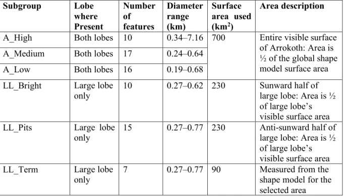
Fig. 6. Craters and Pits on Arrokoth. A. Locations of features considered for crater analysis: numbers refer to crater listings in Data S3. Color denotes confidence class: pink = high confidence (A_High), yellow = medium confidence (A_Medium), light blue = low confidence (A_Low). Features indicated in white are considered to be highly unlikely to be of impact origin and are not included in the crater statistics. The solid white line splits the large lobe into regions with differing lighting conditions, a more obliquely-illuminated region with more visible depressions (LL_Pits, left) and a more vertically-illuminated region with bright spots (LL_Bright, right). The white dashed curve delineates the boundary of combined geologic units ta, td, tc, and td, (LL_Term), considered together for crater density determination. The star symbols indicate the planetocentric subsolar point on each lobe according to the shape model. Lighting direction is shown in Fig 1C. B. The size-frequency distribution of craters on Arrokoth for each crater subgroup and region described in the text and shown in panel A, and (9). The yellow curve includes both high and medium confidence classes, and the light blue curve includes all confidence classes. Parenthetical numbers are the total number of craters/pits in each category. The Arrokoth crater data are compared to crater densities on Charon’s Vulcan Planitia (39) without diameter adjustments for gravity or velocity scaling, and to predictions based on an impactor flux model for six different ages of surfaces on Arrokoth and gravity regime scaling (blue curves with different line styles, (5)). The LL_Term and LL_Bright distributions are offset horizontally by ± 9% for clarity. The empirical saturation line refers to a D-3 differential power law distribution (72).
13
Potential small craters were subdivided in three ways (see Fig. 6A, (9)): (i) all pits and bright patches were subdivided based on our confidence that they are impact craters, (ii) features on the large lobe were subdivided into pits nearer the terminator, and bright patches away from the terminator, as shown in Fig. 6A, and (iii) a combination of geologic units ta, tb, tc, and td, designated “LL_Term” as they are on the large lobe terminator (Fig. 6A), was analyzed separately, because the entire combined unit has low-angle lighting optimal for crater
identification. These subdivisions yielded a range of plausible crater densities, shown in Fig. 6B as a crater relative- or R-plot (9). Overall R values for each dataset are somewhat uncertain as they depend on the areas used for each distribution, and densities are lower if uncertain craters are excluded. The resulting uncertainty range of crater densities is less than a factor of 10 in each diameter bin in Fig. 6B.
Besides Maryland, all other possible impact features are 1 km in diameter or smaller. While the diameter gap between Maryland and second-largest crater on Arrokoth is large, the gap does not strongly disfavor a single power-law size distribution for the craters. We tested a model crater population with a power-law size distribution with slope q = -2 against the observed Arrokoth craters in the combined “A_High” and “A_Medium” categories. The resulting Anderson-Darling statistic indicates no substantial disagreement between the model and observed sample, with a significance level of p ≤ 17%.
Our analysis shows that Arrokoth appears to be only modestly cratered, relative to heavily cratered small objects like Phobos (Fig. S2), and there are some areas on Arrokoth where very few, if any, potential craters exist, in particular the part of the large lobe between the dashed and solid white lines in Fig. 6A.
The age of the surface can be estimated from the observed crater density. We converted impact flux estimates for Arrokoth to crater densities corresponding to several surface ages (5) and show these in Fig. 6B. The resulting age estimates are uncertain, given the uncertainty in identifying which craters are impact-generated, and because the model curves shift based on the crater scaling parameters used. Scaling in the strength regime, as opposed to scaling in the gravity regime assumed here (5), could in principle reduce the sizes of craters produced, if the surface strength of Arrokoth were sufficiently high. The expected strengths of porous cometary surfaces are, however, generally low enough (~1 kPa or less (32)) that the observed craters on Arrokoth should have formed in the gravity regime. In contrast, accounting for the additional cratering in an early but brief dynamical instability phase in the outer Solar System (33) would shift the model curves in Fig. 6B upward, although possibly by no more than a factor of two (5). Low relative densities of small craters are also observed on near-Earth asteroids, and are
conventionally explained as due to seismic shaking from larger impacts or surface evolution due to changes in spin state (34,35,36). However, Arrokoth’s spin state is likely to have evolved only very slowly (18), there do not appear to be sufficient impacts to act as effective seismic sources, and Arrokoth’s likely high porosity would make seismic energy propagation highly inefficient. Overall, despite the paucity of craters on its surface, the observed crater density is consistent with a crater retention age of greater than ~4 billion years. The visible surface at the scale of the LORRI image resolution thus plausibly dates from the end of Solar System
accretion.
Though the diameters of observed craters on Arrokoth (apart from Maryland) are smaller than those measured in the Pluto system, the slopes of the Arrokoth and Pluto system craters are consistent given the small number statistics. Using the Approximate Bayesian Computation
14
forward-modeling methods (37, 38), we estimated the posterior probability density functions for the parameters of independent truncated power-law crater size-frequency distribution models for Arrokoth's and Charon's (39) observed crater populations (for craters < 10 km diameter, below the break in slope observed on Charon). We then conducted the same analysis for a model with a common slope q between the two populations, but a separate offset. The mean slope q = -1.8
+0.4
-0.6 for Charon alone, q = -2.3+0.6-0.6 for Arrokoth alone, and q = -2.0+0.4-0.3 for the joint set
(95% confidence). However, as seen in Fig. 6B, crater density on Arrokoth is higher than would be obtained from an extrapolation of the Charon slope and density to sub-km craters.
Satellites and Rings
Prior to the Arrokoth flyby, constraints on the prevalence of satellites and rings around sub-100 km diameter Kuiper Belt objects were limited. Larger CCKBOs are frequently members of orbiting binary pairs (40). Satellites with a primary/secondary brightness ratio larger than 20 have not been found for KBOs smaller than 500 km diameter (41), though this is likely in part due to observational biases. In contrast, satellites with high primary/secondary brightness ratio are common around large KBOs in non-CCKBO populations. The presence or absence of satellites provides a constraint on formation of the Arrokoth contact binary (e.g. a satellite could potentially remove angular momentum from the central body). At least two known asteroid contact binaries have small satellites: the large Trojan asteroid Hektor has a satellite which orbits at only 5 times the primary radius and has a diameter of 5% of the primary (42), and the large bi-lobed main-belt asteroid Kleopatra has two known satellites orbiting at 8 and 12 times the primary radius, with diameters 6% that of the primary (43).
New Horizons conducted a nested series of satellite searches with the LORRI camera during its approach to Arrokoth, using stacks of many images taken using 4x4 pixel binning to increase sensitivity and reduce data volume. Our dataset allows a deeper and broader search than previously reported (1,9). No satellites have been found. We can exclude satellites larger than 100 – 180 meters in diameter (~0.5% the diameter of the primary) on orbits ranging from Arrokoth’s surface to 8000 km radius, and < 300 m diameter throughout most of the Hill sphere (the region within which a moon could be gravitationally bound to Arrokoth), assuming albedos similar to Arrokoth itself (Fig. 7). Satellites analogous to those of Hektor and Kleopatra can thus be excluded. 102 103 104 105 Search Radius, km 0.01 0.10 1.00 10.00
Limiting Satellite Diameter, km
Hill Radius
Satellites Excluded
Fig. 7. Upper limits on possible satellites of Arrokoth. Excluded regions are plotted as a function of radius from the primary center of mass. The limits assume a satellite with photometric properties similar to Arrokoth itself.
Gravitationally bound objects must lie within the Hill radius (dashed line), which is calculated assuming Arrokoth has a density of 500 kg m-3.
15
The prevalence of rings around small KBOs is poorly constrained, but they are known around Chariklo (44), Haumea (45), and perhaps Chiron (46). We searched for rings and dust clouds within the Arrokothenvironment at all phases of the encounter. The LORRI satellite searches on approach, discussed above, constrained backscattered light due to any ring or dust clouds to I/F ≲ 2 × 10⁻⁷ (19) at 11º phase for a 10-km-wide ring, assuming neutral colors (1). This limit is
fainter than Jupiter’s main ring (I/F = 7 x 10⁻⁷ at 11º phase, (47)). We also conducted dedicated
ring searches in forward-scattered light after closest approach, using images taken 1.7 – 2.3 hours after closest approach at a phase angle of 168º, covering radii up to 6,000 km from Arrokoth. The MVIC instrument, which has better rejection of scattered sunlight than LORRI, was used in its panchromatic framing mode, with total exposure times of 30 seconds. Reduction and analysis followed methodologies used for similar Pluto data (48). No rings or dust structures were detected, with an upper limit I/F of ~1.5 x 10⁻⁶ for structures wider than about 10 km in
Arrokoth’s equatorial plane (Fig. S4). Any ring around Arrokoth is thus also fainter in forward scattering than Jupiter’s main ring (I/F = 4 x 10⁻⁶ at this phase angle, (47)).
New Horizons’ Student Dust Detector (SDC) instrument (49) detected no signals above the noise threshold within ± 5 days of the Arrokoth encounter, implying that there were no impacts by dust particles > 1.6 µm in radius, giving a 90% confidence upper limit of 3 x 10⁷ particles km-2. For
10% albedo, this is equivalent to an I/F limit of 3 x 10-11, even more constraining than the optical
limit, for particles of this size or larger along the spacecraft trajectory.
Comparison to Other KBOs, and to Possible Captured KBOs
Though most other known CCKBOs are larger than Arrokoth, due to observational biases, Arrokoth appears typical of CCKBOs using the few metrics that can be directly compared. Arrokoth’s 0.6 µm geometric albedo, 0.23, is within the known range of other CCKBOs (50). Rotational lightcurves suggest that up to 25% of larger CCKBOs could be contact binaries like Arrokoth (13), though contact binaries appear to be more abundant, up to 50%, in the Plutino population (51). Arrokoth’s color is also typical of CCKBOs (1,3).
Many irregular satellites of the giant planets may be captured KBOs, but only three have resolved spacecraft images. Neptune’s satellite Triton, diameter 2700 km, is far too large and active to be a useful comparison body to Arrokoth. Neptune’s smaller irregular satellite Nereid,
170 km in diameter, has a geometric albedo of 0.16 – 0.20, similar to Arrokoth, but is neutral in color (52). Saturn’s 210 km diameter irregular satellite Phoebe (possibly a captured Kuiper Belt Object (53), though perhaps instead a captured C-type asteroid (54,55)), is darker (geometric albedo 0.08 (56)) and less red (57), and has a completely different surface appearance, dominated entirely by impact features (58). If Phoebe ever resembled Arrokoth, it has been drastically altered by subsequent evolution.
Comparison to Jupiter Family Comets
A class of objects previously explored by spacecraft that may be analogous to Arrokoth in
ultimate origin are the Jupiter Family Comets (JFCs). These differ from Arrokoth in three major respects: (i) Provenance: the vast majority of these bodies likely originated in the Kuiper belt, but from a different family of KBOs: the population of “scattered KBOs” which likely originated closer to the sun than Arrokoth, and whose orbits are strongly perturbed by gravitational
interactions with Neptune (59); (ii) Size: the effective spherical diameters of the JFC nuclei visited by spacecraft are 3 to 18 times smaller than that of Arrokoth; (iii) Thermal history: JFCs
16
have experienced intense solar heating which has heavily modified their surfaces. By comparing the properties of Arrokoth and JFC nuclei, we can explore the effects of these differences.
The JFC nuclei visited by spacecraft have diverse shapes and surfaces (Fig. 8, Fig. S3 and Table S3)). Comets 19P, 67P, and 103P appear to be highly
elongated bilobate objects, suggesting the merger of two distinct bodies, as has been proposed for Arrokoth (1,18), though for comets it is also possible that thermal evolution has generated this shape (e.g., 60). Except for 67P, whose bulk density is 538 ± 1 kg m-3 (16), the
densities of the other JFC nuclei are uncertain by a factor of two or more, but all are consistent with ~500 kg m-3 (61), which implies
average bulk porosities of ~50-80%. Arrokoth’s density is likely greater than 290 kg m-3 (see above), and
thus at least consistent with those of JFC nuclei. The rotation period of Arrokoth is similar to those measured for 67P and 103P and falls well within the range measured for the JFC population (62), though JFC rotation is known to be affected by cometary activity (63).
The JFC nuclei listed in Table S3 are much darker than Arrokoth, with ~3 - 5 times smaller geometric albedos. If the JFC nuclei once had higher albedos in their nascent state in the Kuiper belt, then the darkening of their surfaces might be associated with cometary activity while the JFCs are in the inner Solar System. Most surface features on JFC nuclei have been attributed to cometary activity (e.g., 64, 65). Generally, the surfaces of JFC nuclei can be divided into “smooth” and “rough” (or “mottled”) regions, with the rough terrains associated with a preponderance of pits/depressions or mounds/hills (66,67). The smooth regions of JFCs are generally brighter than average and are often associated with topographic lows, suggesting accumulation by small grains that scatter light more efficiently than the average surface, as we proposed for Arrokoth above. However, on comets the fallback of grains ejected by sublimation is likely to be contribute to smooth terrains (68), and this is less likely to be important on
Arrokoth where evidence for sublimation erosion is limited to the pit chains of possible Fig. 8. Comparison of JFC nuclei to Arrokoth. The images of JFC
nuclei have phase angles similar to those of the highest resolution image of Arrokoth, except for 103P, which was only observed at much higher phase angles. A: Rosetta image of 67P/Churyumov– Gerasimenko (73); B: New Horizons image of Arrokoth (this paper); C: Extrasolar Planet Observation and Characterization / Deep Impact Extended Investigation (EPOXI) image of 103P/Hartley (74); D: Stardust image of 9P/Tempel (75) E: Stardust image of 81P/Wild (76); F: Deep Space 1 image of 19P/Borrelly (77, 78, credit: NASA/JPL). Each frame is scaled so that the body nearly fills it, with the true relative sizes of each body indicated by the scale bars. Arrokoth is much larger than these comets. Figure S3 shows the equivalent images scaled to the same linear resolutions.
17
sublimation origin, and tentative evidence for scarp retreat on the small lobe, as mentioned above.
While the large (multi-kilometer) scale bilobate morphology of Arrokoth is similar to 4 out of the 6 comets listed in Table S3 (see also Figs. 8, S3), the finer surface textures are not. JFCs imaged at the same resolution as Arrokoth show fewer impact craters than Arrokoth (64), consistent with these comets having highly erosional surfaces. They may lose their surfaces at ~0.5-1.0 m per orbit (69) with 5-10 yr orbital periods, so small pits will be removed within a few thousand years. They also show a much rougher surface texture at the 50-100 m scale, consistent with sublimation erosion and loss of most of the erosional debris.
Conclusions
Our dataset from the New Horizons flyby of Arrokoth provides a more complete picture of the physical nature of this object. Images taken on approach show that while both components of Arrokoth are flattened, the flattening is less extreme than initially inferred (1), and the two components have a larger volume ratio, 1.9 ± 0.5 than previous estimates. Stereo topography and the highest resolution imaging taken during the flyby show that the large lobe is very flat on the encounter hemisphere. If the large lobe is composed of multiple components which accreted separately, as previously proposed (1), the topographic signature of the boundaries between the components would be expected to be large initially, if the sub-units were mechanically similar to the two present lobes at the time of their coming into contact (18). The observed flatness of the large lobe shows that any such discontinuities have been subdued, and in some cases eliminated entirely. If subsequent deposition subdued the boundaries, post-depositional processes must be invoked to explain why many of the boundaries are still visible as differences in surface texture or as linear albedo features. Alternatively, the large lobe may be a monolithic body, and the apparent division into sub-units may be due entirely to secondary processes. Multiple processes, including impacts, have reworked the surfaces of both lobes after their formation, producing the fissures, small dark hills, and sinuous albedo boundaries seen in the images.
Crater densities on Arrokoth are low but consistent with a surface age of > 4 Ga, due to the expected low cratering rates in the CCKB, even if only craters with the highest confidence of being impact features are included in the counts. This dates the surface as plausibly from the end of Solar System accretion. Crater size-frequency distribution slopes for < 1 km craters on
Arrokoth are poorly constrained, but are consistent with the slopes seen for 2 – 15 km craters in the Pluto system (39), suggesting that the shallow size-frequency distribution for 0.2 - 2 km diameter KBO impactors found by (39) may persist down to smaller sizes.
Arrokoth is unlike other small bodies visited by spacecraft. The surfaces of comets are
dominated by volatile loss and sublimation erosion driven by the thermal energy inputs, due to their position in the inner Solar System. The surfaces of asteroids are dominated by high-energy impacts. As a result, asteroid surfaces are primarily rubble or impact ejecta. In both cases the dominant energy environment (thermal and impact) is driving the surface morphology.
Arrokoth’s surface is probably a consequence of its presence in the CCKB, where there is much less energy input. The very small relative velocities in this dynamical population result in few impacts and those that do occur have very slow impact velocities. Without strong energy inputs either from solar radiation or impacts, the surface of Arrokoth is expected to be dominated by low level energy inputs from interstellar, solar, and micro-meteorite energy sources at slow rates, likely extending to just a few meters depth (27). It is this low-energy environment that has allowed its surface to be preserved for four billion years.
18
Arrokoth appears to be a typical CCKBO, to the extent that we can compare it to others, so it can be used to understand the cold classical belt as a whole. The bi-lobed nature of Arrokoth might be common in the Kuiper Belt, and could indicate that the bi-lobed shape of many comet nuclei is a primordial feature. In addition, Arrokoth appears to be a direct product of accretion rather than a collisional fragment, and is much smaller than the ~100 km diameter of the break in slope of the size-frequency distribution of CCKBOs (6,70). These facts are consistent with the break in slope being a primordial feature, as predicted by streaming instability models (71). Arrokoth’s appearance is much less consistent with the break in slope being a result of later destruction of small CCKBOs by collisions, a hypothesis also inconsistent with the observed deficit of small craters in the Pluto system (39).
References and Notes:
1. S. A. Stern. et al., Initial results from the New Horizons exploration of 2014 MU69, a small Kuiper Belt Object. Science 364, eaaw9771 (2019). doi: 10.1126/science.aaw9771. 2. S. B. Porter, et al., High-precision orbit fitting and uncertainty analysis of (486958) 2014
MU69. Astron. J. 156, 20. (2018). doi: 10.3847/1538-3881/aac2e1.
3. W. M. Grundy, et al., Color, composition, and thermal environment of Kuiper Belt Object (486958) Arrokoth, Science, this issue (2019).
4. J.-M. Petit, et al., The Canada-France Ecliptic Plane Survey - full data release: The orbital structure of the Kuiper belt. Astron. J. 142, 131.1-24 (2011). doi:
10.1088/0004-6256/142/4/131.
5. S. Greenstreet, B. Gladman, W. B. McKinnon, J. J. Kavelaars, K. N. Singer, Crater density predictions for New Horizons flyby target 2014 MU69. Astrophys. J.. Lett., 872:L5. (2019). doi: 10.3847/2041-8213/ab01db
6. S. Greenstreet, B. Gladman, W. B. McKinnon, Impact and cratering rates onto Pluto. Icarus
258, 267-288. (2015). doi: 10.1016/j.icarus.2015.05.026.
7. A. F. Cheng, et al., Long-Range Reconnaissance Imager on New Horizons. Space Science
Reviews 140, 189-215. (2008). doi: 10.1007/s11214-007-9271-6.
8. D. C. Reuter, et al., Ralph: A Visible/Infrared Imager for the New Horizons Pluto/Kuiper Belt mission. Space Science Reviews 140, 129-154 (2008). doi: 10.1007/s11214-008-9375-7 9. Materials and methods are available as supplementary materials.
10. S. D. Benecchi, et al., The HST lightcurve of (486958) 2014 MU69. Icarus, in press (2019). doi: 10.1016/j.icarus.2019.01.023
11. Buie, M. W., et al,. Size and shape constraints of (486958) Arrokoth from stellar occultations (2020). https://arxiv.org/abs/2001.00125.
12. A. M. Zangari, et al., The mysterious missing light curve of (486958) 2014 MU69, a bi-lobate contact binary visited by New Horizons. Lunar Planet. Sci. Conf. 3007 (2019). 13. A. Thirouin, S. S. Sheppard, Light curves and rotational properties of the pristine Cold
Classical Kuiper Belt objects. Astron. J. 157, 228. (2019). doi: 10.3847/1538-3881/ab18a9. 14. S. B. Porter, et al., New Horizons distant observations of Cold Classical KBOs.
19
15. A. J. Verbiscer, et al., Phase curves from the Kuiper belt: photometric properties of “distant” KBOs observed by New Horizons. Astron. J., 158, id 123 (2019). doi: 10.3847/1538-3881/ab3211.
16. F. Preusker, et al., The global meter-level shape model of comet
67P/Churyumov-Gerasimenko. Astron. Astrophys. 607, id.L1, (2017). doi: 10.1051/0004-6361/201731798. 17. D. J. Scheeres, Orbital Motion in Strongly Perturbed Environments: Applications to
Asteroids, Comet and Planetary Satellite Orbiters (Springer-Praxis, Chichester, 2012).
18. W. B. McKinnon, et al., The solar nebula origin of (486958) Arrokoth, a primordial contact binary in the Kuiper Belt. Science, this issue (2019).
19. Normal reflectance is the I/F (where I is the scattered intensity from the surface and pF is the solar flux at the distance of the scattering surface; also called the bidirectional reflectance) when the incident and emission angles are both zero.
20. B. Buratti, J. Veverka, J., Voyager photometry of Europa. Icarus 55, 93 - 110 (1983). doi:
10.1016/0019-1035(83)90053-2.
21. S. Besse, P. Lamy, L. Jorda, S. Marchi, C. Barbieri, Identification and physical properties of craters on Asteroid (2867) Steins. Icarus, 221, 1119-1129 (2012). doi:
10.1016/j.icarus.2012.08.008.
22. M. S. Robinson, P. C. Thomas, J. Veverka, S. L. Murchie, B. B. Wilcox, The geology of 433 Eros. Meteoritics and Planetary Science, 37, 1651-1684 (2002), doi:
10.1111/j.1945-5100.2002.tb01157.x.
23. L. Prockter, et al., Surface expressions of structural features on Eros. Icarus 15), 75–93 (2002). https://doi.org/10.1006/icar.2001.6770.
24. D. L. Buczkowski, O. S. Barnouin-Jha, L. M. Prockter, 433 Eros lineaments: Global mapping and analysis. Icarus 193, 39–52 (2008). doi: 10.1016/j.icarus.2007.06.028.
25. S. J. Morrison, P. C. Thomas, M. S. Tiscareno, J. A. Burns, J. Veverka, Grooves on small Saturnian satellites and other objects: Characteristics and significance. Icarus 204, 262–270. (2009). doi: 10.1016/j.icarus.2009.06.003.
26. T. A. Hurford, et al., Tidal disruption of Phobos as the cause of surface fractures. J. Geophys.
Res.: Planets 121, 1054–1065 (2016). doi: 10.1002/2015JE004943.
27. S. A. Stern, The evolution of comets in the Oort cloud and Kuiper belt. Nature 424, 639-642 (2003).
28. M. J. S. Belton, et al. The internal structure of Jupiter family cometary nuclei from Deep Impact observations: The “talps” or “layered pile” model. Icarus 187, 332-344 (2007). doi:
10.1016/j.icarus.2006.09.005
29. M. Jutzi, E. Asphaug, The shape and structure of cometary nuclei as a result of low-velocity accretion. Nature 348, 1355-1358 (2015). doi: 10.1126/science.aaa4747.
30. K. R. Housen, W. J. Sweet, K. A. Holsapple, Impacts into porous asteroids. Icarus 300, 72– 96 (2018). doi: 10.1016/j.icarus.2017.08.019.
20
31. S. J. Robbins, et al., Measuring impact crater depth throughout the solar system. Meteoritics
and Planetary Science 53, 583-637 (2018). doi: 10.1111/maps.12956.
32. K. A. Holsapple, K. R. Housen, A crater and its ejecta: An interpretation of Deep Impact.
Icarus 191, 586–597 (2007). doi: 10.1016/j.icarus.2006.08.035.
33. D. Nesvorný, Dynamical evolution of the early Solar System. Ann. Rev. Astron. Astrophys.
56, 137 (2018). doi: 10.1146/annurev-astro-081.
34. S. Sugita, et al., The geomorphology, color, and thermal properties of Ryugu: Implications for parent-body processes. Science 364, 252-252 (2019). doi: 10.1126/science.aaw0422. 35. K. J. Walsh, et al., Craters, boulders and regolith of (101955) Bennu. Nature Astron.
12, 242–246 (2019). doi: 10.1038/s41561-019-0326-6.
36. D. J. Scheeres, et al., The dynamic geophysical environment of (101955) Bennu based on OSIRIS-REx measurements. Nature Astron. 3, 352–361 (2019). doi: 10.1038/s41550-019-0721-3.
37. A. H. Parker, The intrinsic Neptune Trojan orbit distribution: Implications for the primordial disk and planet migration. Icarus 247, 112-125 (2015). doi: 10.1016/j.icarus.2014.09.043. 38. S. Mazrouei, R. R. Ghent, W. F. Bottke, A. H. Parker, T. M. Gernon, Earth and Moon impact
flux increased at the end of the Paleozoic. Science 363, 253-257 (2019). doi:
10.1126/science.aar4058.
39. K. N. Singer, et al., Impact craters on Pluto and Charon indicate a deficit of small Kuiper belt objects. Science 363, 955-959 (2019). doi: 10.1126/science.aap8628.
40. K. S. Noll, W. M. Grundy, D. Nesvorný, A. Thirouin, “Transneptunian binaries” in The
Trans-Neptunian Solar System, D. Prialnik, M. A. Barucci, L. Young, Eds. (Elsevier, 2019),
pp. 205-224.
41. W. R. Johnston, Binary Minor Planets Compilation V3.0.
urn:nasa:pds:ast_binary_parameters_compilation::3.0. NASA Planetary Data System, (2019),
https://sbn.psi.edu/pds/resource/binmp.html.
42. F. Marchis, et al., The puzzling mutual orbit of the binary Trojan asteroid (624) Hektor.
Astrophys. J. 783, L37 (2014). doi: 10.1088/2041-8205/783/2/L37.
43. Descamps, P., et al., Triplicity and physical characteristics of Asteroid (216) Kleopatra.
Icarus 211, 1022-1033 (2011). doi: 10.1016/j.icarus.2010.11.016.
44. F. Braga-Ribas, et al., A ring system detected around the Centaur (10199) Chariklo. Nature
508, 72–75 (2014). doi: 10.1038/nature13155
45. J. L. Ortiz, et al., The size, shape, density and ring of the dwarf planet Haumea from a stellar occultation. Nature 550, 219–223 (2017). doi: 10.1038/nature24051.
46. J. L. Ortiz, et al., Possible ring material around centaur (2060) Chiron. Astron. Astrophys.
576, A18 (2015). doi: 10.1051/0004-6361/201424461.
47. H. B. Throop, et al., The Jovian rings: New results derived from Cassini, Galileo, Voyager, and Earth-based observations. Icarus 172, 59–77 (2004). doi: 10.1016/j.icarus.2003.12.020
21
48. T. R. Lauer, et al., The New Horizons and Hubble Space Telescope search for rings, dust, and debris in the Pluto-Charon system. Icarus 301, 155-172 (2018). doi:
10.1016/j.icarus.2017.09.033.
49. M. Horanyi, et al., The Student Dust Counter on the New Horizons Mission. Space Sci. Rev.
140, 387-402 (2008). doi: 10.1007/s11214-007-9250-y.
50. P. Lacerda, et al., The albedo-color diversity of transneptunian objects. Astrophys. J. 793, L2 (2014). doi: 10.1088/2041-8205/ 793/1/L2
51. A. Thirouin, S. S. Sheppard, The Plutino population: An abundance of contact binaries.
Astron. J. 155, id 248 (2018). doi: 10.3847/1538-3881/aac0ff.
52. P. Thomas, J. Veverka, P. Helfenstein, Voyager observations of Nereid. J. Geophys. Res. 96, 19253 (1991). doi: 10.1029/91JA01735.
53. T. V. Johnson, J. Lunine, Saturn's moon Phoebe as a captured body from the outer Solar System. Nature 435, 69-71 (2005). doi: 10.1038/nature03384.
54. W. K. Hartmann, A satellite-asteroid mystery and a possible early flux of scattered C-class asteroids. Icarus 71, 57-68 (1987). doi: 10.1016/0019-1035(87)90162-X
55. J. Castillo-Rogez, P. Vernazza, K. Walsh, Geophysical evidence that Saturn's Moon Phoebe originated from a C-type asteroid reservoir. Monthly Notices Royal Astron. Soc. 486, 538 (2019). doi: 10.1093/mnras/stz786.
56. D. P. Simonelli, et al., Phoebe: Albedo map and photometric properties. Icarus 138, 249-258 (1999). doi: 10.1006/icar.1999.6077.
57. B. J. Buratti, M. D. Hicks, K. A. Tryka, M. S. Sittig, R. L. Newburn, High-resolution 0.33– 0.92 mm spectra of Iapetus, Hyperion, Phoebe, Rhea, Dione, and D-type asteroids: How are they related? Icarus 155, 375–381 (2002). doi: 10.1006/icar.2001.6730.
58. C. C. Porco, et al., Cassini Imaging Science: Initial Results on Phoebe and Iapetus. Science
307, 1243-1247 (2005). doi: 10.1126/science.1107981
59. M. Duncan, H. Levison, L. Dones, “Dynamical evolution of ecliptic comets”. In Comets II, M. C. Festou, H. U. Keller, H. A. Weaver Eds. (University of Arizona Press, Tucson, 193, 2004).
60. D. E. Vavilov, S. Eggl, Y. D. Medvedev, P. B. Zatitskiy, Shape evolution of cometary nuclei via anisotropic mass loss. Astron. Astrophys. 622, L5 (2019). doi:
10.1051/0004-6361/201834806.
61. O. Groussin, et al., The thermal, mechanical, structural, and dielectric properties of cometary nuclei after Rosetta. Space Sci. Rev. 215, id 29 (2019). doi: 10.1007/s11214-019-0594-x. 62. R. Kokotanekova, et al., Rotation of cometary nuclei: new light curves and an update of the
ensemble properties of Jupiter-family comets. Monthly Notices Royal Astron. Soc. 471, 2974-3007 (2017). doi: 10.1093/mnras/stx1716.
63. D. Bodewits, T. L. Farnham, M. S. P. Kelley, M.M Knight, A rapid decrease in the rotation rate of comet 41P/Tuttle-Giacobini-Kresák. Nature 553, 186-188 (2018). doi:
22
64. J. Sunshine, N. Thomas, M. R. El-Maarry, T. L. Farnham, Evidence for geologic processes on comets. J. Geophys. Res. Planets, 121 (2016). doi: 10.1002/2016JE005119.
65. M. R. El-Maarry, et al., Surface changes on comet 67P/Churyumov-Gerasimenko suggest a more active past. Science 355, 1392–1395 (2017). doi: 10.1126/science.aak9384.
66. P. C. Thomas, et al., Shape, density, and geology of the nucleus of Comet 103P/Hartley 2.
Icarus 222, 550-558 (2013). doi: 10.1016/j.icarus.2012.05.034.
67. D. T. Britt, et al., The morphology and surface processes of Comet 19/P Borrelly. Icarus
167, 45-53 (2004). doi: 10.1016/j.icarus.2003.09.004.
68. N. Thomas, et al., Redistribution of particles across the nucleus of comet 67P/Churyumov-Gerasimenko, Astron. Astrophys. 583, A17 (2015). DOI: 10.1051/0004-6361/201526049
69. D. Prialnik, J. Benkhoff, M. Podolak, “Modeling the structure and activity of comet nuclei”. In Comets II, M. C. Festou, H. U. Keller, H. A. Weaver Eds. (University of Arizona Press, Tucson, 2004) p.359-387.
70. W. C. Fraser, M.E. Brown, A. Morbidelli, A. Parker, K. Batygin, The absolute magnitude distribution of Kuiper Belt Objects. Astrophys. J. 782, 100. (2014). doi: 10.1088/0004-637X/782/2/100
71. R. Li, A. N. Youdin, J. B. Simon, Demographics of planetesimals formed by the streaming instability. Astrophys. J. 885, 69 (2019). doi: 10.3847/1538-4357/ab480d
72. H. J. Melosh, Impact cratering : a geologic process. (Oxford University Press, Oxford, Clarendon Press, 1989).
73. H. Sierks, et al. On the nucleus structure and activity of comet 67P/Churyumov-Gerasimenko. Science 347, aaa1044 (2015). doi: 10.1126/science.aaa1044. 74. M. F. A'Hearn, et al., EPOXI at Comet Hartley 2. Science 332, 1396 (2011). doi:
10.1126/science.1204054.
75. J. Veverka, et al., Return to Comet Tempel 1: Overview of Stardust-NExT results. Icarus
222, 424-435 (2013). doi: 10.1016/j.icarus.2012.03.034.
76. D. E. Brownlee, et al., Surface of Young Jupiter Family Comet 81 P/Wild 2: View from the Stardust Spacecraft. Science 304, 1764-1769 (2004). doi: 10.1126/science.1097899.
77. L. A. Soderblom, et al., Observations of Comet 19P/Borrelly by the Miniature Integrated Camera and Spectrometer Aboard Deep Space 1. Science 296, 1087-1091 (2002). doi:
10.1126/science.1069527.
78. B. J. Buratti, M. D. Hicks, L. A. Soderblom, D. Britt, J. Oberst, J. K. Hillier, Deep Space 1 photometry of the nucleus of Comet 19P/Borrelly. Icarus 167, 16-29 (2004). doi:
10.1016/j.icarus.2003.05.002.
79. J. R. Spencer et al., Data archive for Spencer et al. 2020, The geology and geophysics of Kuiper Belt object (486958) Arrokoth, Science, figshare (2020); https://doi.org/10.6084/ m9.figshare.11485443.