HAL Id: hal-00648899
https://hal.archives-ouvertes.fr/hal-00648899v2
Submitted on 8 Feb 2012
HAL is a multi-disciplinary open access
archive for the deposit and dissemination of sci-entific research documents, whether they are pub-lished or not. The documents may come from teaching and research institutions in France or abroad, or from public or private research centers.
L’archive ouverte pluridisciplinaire HAL, est destinée au dépôt et à la diffusion de documents scientifiques de niveau recherche, publiés ou non, émanant des établissements d’enseignement et de recherche français ou étrangers, des laboratoires publics ou privés.
multilayers for EUV applications
M.-H. Hu, K. Le Guen, Jean-Michel André, S.-K. Zhou, H.-C. Li, J.-T. Zhu,
Z.-S. Wang, C. Meny, N. Mahne, Angela Giglia, et al.
To cite this version:
M.-H. Hu, K. Le Guen, Jean-Michel André, S.-K. Zhou, H.-C. Li, et al.. Investigation of the thermal stability of Mg/Co periodic multilayers for EUV applications. Applied physics. A, Materials science & processing, Springer Verlag, 2011, 106, pp.737-745. �10.1007/s00339-011-6681-9�. �hal-00648899v2�
1
Investigation of the thermal stability of Mg/Co periodic
multilayers for EUV applications
M.-H. Hu1 , K. Le Guen1 , J.-M. André1 , S. K. Zhou2 , H. Ch. Li2 , J. T. Zhu2 , Z. S. Wang2 , C. Meny3 , N. Mahne4 , A. Giglia4 , S. Nannarone4,5 , I. Estève6 , M. Walls7 , P. Jonnard1
(1) Laboratoire Chimie Physique – Matière Rayonnement, UPMC Univ Paris 06, CNRS UMR 7614,
11 rue Pierre et Marie Curie, F-75231 Paris cedex 05, France
(2) Institute of Precision Optical Engineering, Department of Physics, Tongji University, Shanghai
200092, P.R. China
(3) Institut de Physique et Chimie des Matériaux de Strasbourg, CNRS UMR 7504, 23 rue du Loess,
BP 43, F-67034 Strasbourg cedex 2, France
(4) CNR-IOM Laboratorio TASC, SS 14 km 163,5, I-34149 Basovizza, Trieste, Italy
(5) Università di Modenae R.E., Dipartimento Ingegneria Materiali, viaVignolese 905/a, Modena, Italy
(6)Institut de Minéralogie et de Physique des Milieux Condensés, Univ Paris 06 et 07, CNRS UMR
7590, 4 place Jussieu, F-75252 Paris Cedex 05, France
(7) Laboratoire de Physiques des Solides, CNRS UMR 8502, Univ Paris Sud, F-91405 Orsay, France
1
Corresponding author: Dr. Philippe Jonnard, Laboratoire Chimie Physique – Matière et
2 AUTHOR EMAIL ADDRESS [email protected]
TITLE RUNNING HEAD Thermal stability of Mg/Co multilayers
ABSTRACT
We present the results of the characterization of Mg/Co periodic multilayers and their thermal stability
for the EUV range. The annealing study is performed up to a temperature of 400°C. Images obtained by
scanning transmission electron microscopy and electron energy loss spectroscopy clearly show the good
quality of the multilayer structure. The measurements of the EUV reflectivity around 25 nm (~49 eV)
indicate that the reflectivity decreases when the annealing temperature increases above 300°C. X-ray
emission spectroscopy is performed to determine the chemical state of the Mg atoms within the Mg/Co
multilayer. Nuclear magnetic resonance used to determine the chemical state of the Co atoms and
scanning electron microscopy images of cross sections of the Mg/Co multilayers reveal changes in the
morphology of the stack from an annealing temperature of 305°C. This explains the observed
reflectivity loss.
KEYWORDS annealing, interface, multilayer, Mg, Co, scanning transmission electron microscopy,
electron energy loss spectroscopy, EUV reflectivity, nuclear magnetism resonance, x-ray emission
3
1. Introduction
In the extreme ultraviolet (EUV) range, highly efficient periodic multilayers are widely used in
many fields such as X-ray space telescopes, EUV lithography or X-ray laser facilities. The previous
measurements of the optical and interface properties of the Mg/Co multilayer [1, 2] show that this
multilayer is promising for future applications in the wavelength range close to the Mg L edge around
25 nm (or a photon energy of 50 eV) and in particular for the observation of the 30.4 nm He II emission
[3]. In the 25 nm range, a reflectivity of about 43% is measured at 45° for s-polarized radiation.
Another important property often required for multilayer devices is their thermal stability. In fact
multilayers can be subject to high thermal loads, for example, when in use in space telescopes where
they needs to withstand the high temperature space environment. Systems already investigated in this
context include Mg/SiC [4,5] which is thermally stable for applications only up to 200°C and also on
more stable systems such as Mo/Si, Mo/C, W/Si and Fe/Al, etc. [6-11] and more recently Mo/B4C [12].
The present work examines Mg/Co multilayers and their thermal stability by studying
interdiffusion, interfacial compound formation and roughness development. From the phase diagram,
the Mg-Co system is stable in the solid state up to a high temperature. The only possible compound is
Co2Mg. In this work, we study Mg/Co multilayer samples prepared by magnetron sputtering and then
annealed up to 400°C, under ultra-high vacuum. Scanning transmission electron microscopy (STEM)
images and electron energy loss spectroscopy (EELS) give direct evidence of the quality of the layers of
the unannealed multilayer. The measurements of the EUV reflectivity around 25 nm (~49 eV) indicate
the optical property of the multilayers. X-ray emission spectroscopy (XES) and nuclear magnetic
resonance (NMR) are performed to determine the chemical state of the Mg and Co atoms within the
Mg/Co multilayer, respectively. The interest of combining XES and NMR is to obtain the information
4 interface morphology as a function of the annealing temperature.
2. Experimental Section
2.1 SamplesFollowing the multilayer design resulting from simulations [13], we prepared two sets of Mg/Co
multilayers with different periods, Mg/Co_1 and Mg/Co_2 whose parameters are given in Table 1. They
were both deposited onto ultra-smooth polished Si substrates (30 mm × 40 mm) by an ultrahigh vacuum direct current magnetron sputtering deposition system (Model JGP560C, SKY Technology, China)
using Co (99.95% purity) and Mg (99.98% purity) targets. The sample preparation was done at a base pressure of 1×10⁻⁴
Pa. The working gas is argon (99.999% purity) at a constant working pressure
0.13 Pa. The number of periods is 30. In order to prevent oxidation, both multilayers are capped with a
3.5 nm thick B4C layer. For Mg/Co_2, we cut the 15 mm × 15 mm sample into six small pieces of size 7.5 mm × 5 mm in order to do the annealing at different temperatures.
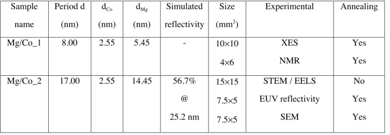
Table 1. Designed structures of the Mg/Co multilayers.
Sample name Period d (nm) dCo (nm) dMg (nm) Simulated reflectivity Size (mm2 ) Experimental Annealing Mg/Co_1 8.00 2.55 5.45 - 10×10 4×6 XES NMR Yes Yes Mg/Co_2 17.00 2.55 14.45 56.7% @ 25.2 nm 15×15 7.5×5 7.5×5 STEM / EELS EUV reflectivity SEM No Yes Yes
5 reflectivity at 0.154 nm of [1]. The structural parameters of the Mg/Co_2 multilayer, deduced from the
fit of the reflectivity curve, show a good agreement between the aimed and effective thicknesses of the
layers and an interfacial roughness of Co-on-Mg and Mg-on-Co layers which are 0.5 and 0.6 nm,
respectively.
To investigate the thermal stability of Mg/Co periodic multilayers, all the Mg/Co multilayers
were annealed at 280, 305 and 400°C for one hour centre in the preparation chamber of the BEAR beamline [14] at the Elettra synchrotron. The base pressure is 1×10⁻⁸
Pa. All samples were annealed for
one hour. The EUV reflectivity measurements were made in situ, that is to say that the sample remained
in a UHV environment. The XES, NMR and SEM measurements were done ex situ after transferring the
samples in air.
The Mg/Co_2 unannealed sample is dedicated to the STEM / EELS (Table 1) analysis. The
Mg/Co_2 annealing samples are dedicated to the reflectivity measurement in the EUV range and SEM
studies in order to characterize the optical properties and the morphology of the multilayers,
respectively. Then the set of Mg/Co_1 annealing samples, which is characterized by a short period, is
dedicated to the XES and NMR analysis in order to study the chemical state of the Mg and Co atoms,
respectively. Indeed, to be able to identify the formation of an interfacial layer at the interface between
two successive layers, the thickness of this interfacial layer should be comparable to that of the layer of
the emitting atoms.
2.2 Scanning transmission electron microscope and electron energy loss spectroscopy
The lamella of the cross section of the unannealed Mg/Co_2 multilayer was examined by STEM
and EELS. A Nion Ultrastem 100 operating at 100 kV and under ultra-high vacuum was used for these
observations. The spherical aberration-corrected probe size was around 0.1 nm. The images are
generated by scanning the focused beam over the lamella. Both energy-loss spectra and high angle
6 technique for materials morphological and chemical characterization at the sub-nanometer level. We
used a probe convergence angle of 35 mrad and a collection angle for the EELS spectrometer of 50
mrad. Spectra were acquired with a dispersion of 1 eV per channel (with a 1024 channel camera) to
have access simultaneously to the Co-L edge (779 eV) and the Mg K edge (1305 eV). The HAADF
collection range was 75 to 200 mrad.
2.3 EUV reflectivity
The EUV reflectivity curves were measured on the BEAR beamline of the Elettra synchrotron
facility using s-polarized light. The absolute uncertainty of the reflectivity values was about 1%. The
photon energy was calibrated with respect to the Pt 4f7/2 and Si L with an accuracy of 0.1 eV. The
intensities of incident and reflected radiation were measured with a solid-state photodiode. The
incoming photon flux was also monitored using an Au mesh inserted into the beam path, whose drain
current was used for normalization.
2.4 Nuclear magnetic resonance spectroscopy
In order to probe the chemical state of the Co atoms within the multilayers, the samples have
been analyzed by zero field NMR. The experiment was performed at 4.2 K using an automated
frequency scanning broadband spectrometer with phase coherent detection [15]. The NMR spectra
represent the distribution of Co atoms versus their resonance frequency [16]. The NMR frequency is
strongly dependent on the number and nature of atoms in its neighborhood and also possibly on the
symmetry of this neighborhood.
2.5 X-ray emission spectroscopy
We have performed XES with a high-resolution wavelength dispersive spectrometer [17] to
identify the chemical state of the Mg atoms within the multilayers. Similar studies have already been performed by this method [18-26]. We observed the shape of the Mg Kβ emission band from the 3p–1s
7 transition which describes the Mg 3p valence states. They are sensitive to the chemical state of the Mg
atoms [27,28]. The energy of the incident electrons used to produce the ionizations necessary to induce
the electron transitions was set to 7.5 keV. The electron beam comes from a Pierce gun. Following the
ionization of the atoms present in the sample, characteristic x-rays were emitted [29,30], then dispersed
by a (100) bent beryl crystal. The radiation was detected in a gas-flux counter working in the Geiger
regime. The spectra of the multilayers were compared to the references, Mg metal and MgO.
2.6 Scanning electron microscopy and focused ion beam
Lamellae of the cross section of the Mg/Co_2 multilayers were prepared by FIB (Focused Ion
Beam) / SEM CrossBeam® workstation NEON40EsB (Carl Zeiss). The FIB/SEM system, combination
of a scanning electron microscope and a Ga+
ion beam, allowed a precise and located milling by
sputtering of material with a simultaneous accurate observation. This FIB/SEM workstation is also
equipped with an in situ gas injection system loaded with platinum gas precursor.
We first deposited a thin carbon rich platinum film (about 15 nm thick) with the electron beam
to protect the sample surface against ion-beam damage. Then a 1 µm thick platinum layer was deposited
with the ion beam. A first cross section of the multilayers is cut and observed by SEM. A lamella,
whose size was approximately 10 µm × 4 µm with a thickness of 1 µm, was excavated, lifted-out in situ using a micromanipulator and glued to a copper half TEM grid. Finally, the lamella was polished to a
thickness of 60 nm, giving the electron transparency needed for TEM. However, further thinning to
about 30 nm in a Gatan PIPS system operating at 1 kV was found to be necessary for the high resolution
imaging and EELS experiments.
3. Results and discussion
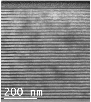
3.1 Samples without annealing8 prepared by FIB. We can clearly distinguish the multilayer structures: from top to bottom are the
substrate, the 30 periods multilayer and the Pt protection layer. The figure shows us the multilayer of
good quality and the layers are smooth. The diffuse nature of the interfaces is probably mostly due to
loss of resolution due to multiple scattering in the thicker parts of the TEM sample (which happens here
to be mainly in the lower part of the figure, in the layers nearest the substrate).
Figure 1. STEM BF image of the unannealed Mg/Co_2 multilayer.
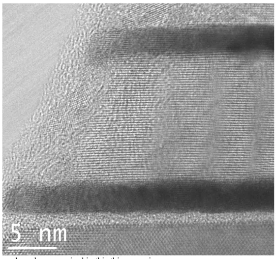
To get a better impression of the quality of the layers we need to zoom onto a part thin enough
(and well oriented enough) to allow visualisation of the crystal structure in the dense Co layers. Figure 2
shows a zoom onto the first two periods of the multilayer in the thinnest part of the sample. The
horizontal fringes have spacings corresponding to those of the hexagonal planes in bulk magnesium and
bulk cobalt in the appropriate regions. Lattice spacings are measured as 0.26 ± 0.01nm in the Mg layer
(c/2 = 0.2605nm in bulk Mg) and 0.21nm ± 0.01nm in the Co layer (c/2 = 0.204nm in bulk Co). Other orientations are sometimes visible, but are probably due, in this thin region, to disordered and/or oxide
layers at the outer surfaces of the STEM sample caused by to ion-beam damage and air exposure. (In
most thicker regions, the hexagonal Mg fringes can be seen but not those of Co, which is too dense).
9 crystallised region is also seen between the substrate and the first Co layer. In order to determine the
nature of this layer and to attempt a further check of the roughness of the layers some preliminary EELS
spectrum-images have been acquired in this thinner region.
Figure 2. Close up of the thinnest part of the unannealed Mg/Co_2 multilayer.
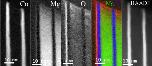
Figure 3 shows Co, Mg, O EELS maps and the corresponding HAADF images from the first two
bi-layers. The layers can be seen to be chemically well-ordered at this scale. A strong oxygen signal is
detected, along with Mg in the poorly crystallised region mentioned above. This appears therefore to be
an MgO layer. The oxygen signal is also slightly enhanced over the Mg layers, probably due to surface
oxidation.
Co
Mg
10
Figure 3. Co, Mg, O EELS maps and the corresponding HAADF images from the first two bi-layers.
Figure 4 shows a higher resolution set of EELS maps going across one Co layer. The vertical
integrations in the dotted boxes give the interface width. The width of the interfaces on both sides is
measured here as approximately 1 nm, i.e. almost twice as much as the figures found by reflectivity.
Convolution with the probe-size of around 0.1 nm cannot account for the entire discrepancy. EELS
signals can suffer from delocalisation, i.e. excitation of an atom by a fast electron passing at a distance
which can be several angstroms. However the effects would not be expected to be very large here,
especially in the case of the high energy-loss Mg K edge. The broadening of the profiles is more likely
to be due to non-negligible multiple elastic and inelastic scattering in the region where the data were
acquired (~40 nm) which is still not ideally thin for 100 keV electrons and these materials, and the
disordered layers seen to be present at the sample surface which almost certainly contain a mixture of
Mg and Co. Further EELS experiments on thinner samples (or using higher acceleration voltages) and
using higher energy resolution should provide further details of the structure and chemistry of the range
of samples studied here.
Mg
11
Figure 4. Higher resolution EELS maps (top) of Co (left) and Mg (right) across the second Co layer and
the interface width profiles (bottom).
3.2 Samples with annealing
EUV reflectivity
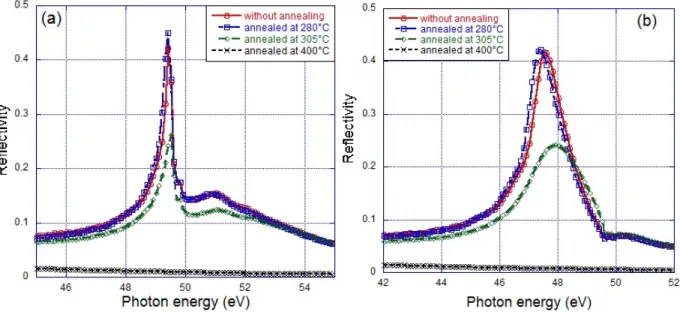
We show in Figure 5 the reflectivity curves as a function of the annealing temperature, measured
in the 45-55 eV energy range at 45° Bragg angle, angle for which the multilayer is designed, and in the
42-52 eV energy range at 50°. At 45° the maximum reflectivity is 42.4% at 49.3 eV, which is close to
0.89nm 0.88nm 1.0nm 1.05nm
Mg
g
Co
12 the Mg-L absorption edge at 49.50 eV for 2p3/2 and 49.78 eV for 2p1/2. This is rather too close to the
Mg-L edge and we prefer to fit the reflectivity curves obtained at 50°. In the following, the position and
maximum position of the Bragg peak will then be discussed for spectra recorded at 50° of grazing
incidence.
Figure 5. Evolution as a function of the annealing temperature of the Mg/Co_2 EUV reflectivity curves
obtained at 45° (a) and 50° (b) Bragg angles.
The reflectivity slightly increases and the position of the Bragg peak of the Mg/Co_2 annealed at
280°C is slightly shifted (0.2 eV) towards lower photon energy with respect to that of the multilayer
without annealing. At 305°C, a reflectivity drop of nearly 45% is observed as well as a peak shift
(0.4 eV) towards higher photon energy. At 400°C, the reflectivity can be considered as zero. The
structural parameters of the stack deduced from the fit of the reflectivity curves measured at 50° are
collected in Table 2. The interfacial roughness and the thickness are stable for the unannealed and
280°C samples. However, the interfacial roughness increases quite a lot for the Mg/Co_2 annealed at
13
Table 2. Parameter values extracted from the fit to the Mg/Co_2 reflectivity curve measured at a Bragg
angle of 50° in the EUV range. σ stands for the interfacial roughness. Multilayer Mg/Co_2 d (nm) dco (nm) dMg (nm) σ (nm) Without annealing 16.9 2.6 14.3 Co-on-Mg = 0.5 Mg-on-Co = 0.6 Annealed at 280°C 16.98 2.86 14.12 Co-on-Mg = 0.5 Mg-on-Co = 0.6 Annealed at 305°C 16.9 3.95 12.95 Co-on-Mg = 1.0 Mg-on-Co = 2.7 NMR analysis
NMR spectra obtained for the Mg/Co_1 multilayers as a function of the annealing temperatures
are presented in Figure 7(a). As can be seen, the spectra shapes of the Mg/Co_1 multilayers after
annealing at different temperatures show a well defined line at 226 MHz which corresponds to Co atoms
lying in the bulk of the Co layers with an hcp structure. The Co atoms are thus mainly situated in pure
Co layers (226 MHz) and the intermixing at the Mg/Co interfaces is limited. An additional line is
observed at 156 MHz for the multilayer without annealing and for the sample annealed at 280°C in
Figure 7(b). This line has been identified in our previous work with the Co atoms situated at perfect
interfaces between Co and Mg atoms [1]. The overall shape of the spectrum after annealing at 280°C is
very similar to that observed for the as deposited sample. It can be noticed that the Co interface line
seems to be even better resolved after annealing at 280°C than in the spectrum of the as deposited
sample. This observation would suggest that such low temperature annealing results in some sharpening
14
Figure 6. (a) NMR spectra of Mg/Co_1 multilayers as a function of the annealing temperatures; (b)
zoom around 156 MHz.
The modification of the NMR spectra is much more significant for higher annealing
temperatures (305 and 400°C). The most striking observation is that the contribution of the Co atoms at
the Co/Mg interfaces (156 MHz) vanishes with increasing annealing temperature, Figure 7(b). This
could be attributed to the formation of non magnetic interfacial alloys or compounds. However this is
not consistent with the XES analysis and the observation that the total NMR intensity is not significantly (a)
15 reduced after annealing.
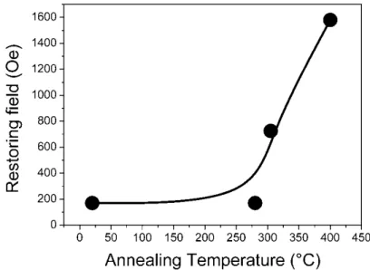
Additional details can be obtained from the magnetic information that is provided by the NMR
experiments. Indeed NMR can also probe the magnetic stiffness of the samples [16]. This stiffness can
have several origins and is described as a magnetic restoring field. The plot of this restoring field versus
the annealing temperature is shown in Figure 8 (room temperature corresponding to 20°C). It can be
seen that while the restoring field stays unchanged after the annealing at 280°C, it increases strongly for
higher annealing temperatures. After the annealing at 400°C the restoring field is an order of magnitude
higher than after the annealing at 280°C. This observation does not support the intermixing process
since such a process usually leads to a decrease in the restoring field. However it shows that the
magnetization processes are drastically modified by the annealing process.
Figure 7. Magnetic restoring field versus the annealing temperature of Mg/Co_1 multilayers.
Actually the vanishing of the interfacial line as well as the increase in the restoring field with the
annealing temperature can both be explained by the clustering of the Co layers into spheres or more
probably into Co grains with pan cake like shapes. Indeed spherical grains would lead to a reorientation
16 film. In such a case the NMR resonance frequency would shift from 226 MHz to 220 MHz [31], which
is not observed in the NMR spectra. The clustering of the Co atoms will result in Co particles for which
the surface to volume ratio is much smaller than in the case for the as deposited multilayer shape. If the
Co grains are large enough, the contribution of the surface Co atoms becomes so small that it is not
measurable anymore. The magnetic properties of Co grains are also very different from those of Co
films. In Co films extended domain wall (Neel walls) can develop, resulting in soft magnetic properties
(small restoring fields in NMR) while in Co grains such domain walls if they exist will have a smaller
mobility, resulting in hard magnetic properties (large restoring fields in NMR). Therefore the clustering
of the Co films into large Co grains with increasing annealing temperature explains both the evolution
of the NMR spectra and the evolution of the magnetic properties of the samples.
XES analysis
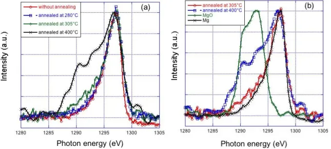
We present in Figure 8 the Mg Kß emission band of the Mg/Co_1 sample as a function of the
annealing temperature and the comparison to the references Mg and MgO. The Mg Kß emission band of
the Mg/Co multilayer without annealing is discussed in detail in Ref. [1].
Figure 8. The Mg Kß emission band of sample Mg/Co_1 annealed at different temperatures (a) and its
17 The spectrum of the sample annealed at 280°C is close that obtained without annealing and close
to that of Mg metal. We deduce that within the sample annealed at 280°C, the Mg atoms are in a
physico-chemical state close to that of Mg atoms in the Mg metallic state and the interaction with the Co
layers is limited. The spectra of Mg/Co_1 samples annealed at 305°C and 400°C differ from that of
Mg/Co without annealing toward the low photon energies. A shoulder appears in the region of the MgO
maximum (1288-1295 eV) whose intensity increases with temperature. Thus from 305°C an oxidation
of the Mg layer takes place. Because of the annealing conditions, the oxidation takes place after the
EUV measurements when the sample is returned to the air prior their XES analysis. Thus, whatever the
annealing temperature, the Mg atoms do not interact with the Co atoms, which is in agreement with the
NMR result.
SEM analysis
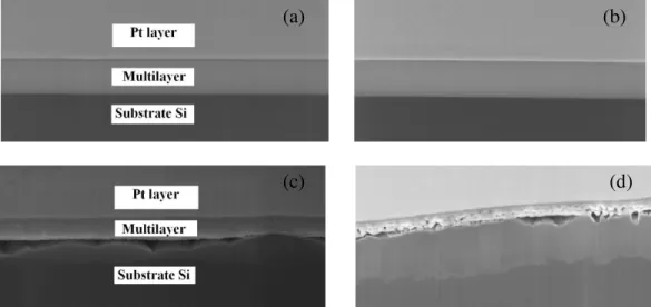
From the SEM images of cross sections presented in Figure 9 we can see that the Mg/Co_2
multilayers without annealing and annealed at 280°C have clear multilayer structures. The cross section
of the samples presents from top to bottom the Pt protection layer, the Mg/Co_2 multilayer and the Si
substrate. For the sample annealed at 305°C, there exist some cracks between the multilayer and the
substrate, the interface is no longer flat and there seems to be a loss of adherence. The sample annealed
at 400°C has more serious changes compared to the sample annealed at 305°C: cracks and voids exist
also between the layers. The change in the multilayer structure results from the change in the
morphology of the Co layers deduced from NMR. The deformation of the Co layers generates
mechanical stress that finally is discharged by the delamination of the multilayer and the formation of
cracks. Because of these cracks, the multilayer is no longer flat and so its reflectivity decreases. Finally,
the cracks facilitate the introduction of oxygen within the multilayer. This explains the oxidation of the
18
Figure 9. SEM images of Mg/Co_2 multilayer without annealing (a), annealed at 280°C (b), 305°C (c)
and 400°C (d).
4. Conclusions
We have characterized a Mg/Co periodic multilayer and its thermal stability by using
STEM / EELS, EUV reflectivity around 25 nm (~50 eV), NMR, XES and SEM. The multilayer is
designed for optical application in the EUV range. STEM / EELS images show the good quality of the
as-prepared multilayer and the crystallization of the Co and Mg layers. EUV reflectivity measurements
show that the reflectivity slightly increases with the temperature up to 280°C. Then, the reflectivity
drops by nearly 45% at 305°C and vanishes at 400°C. The combination of the results obtained by the
various used techniques allows us to explain this reflectivity variation: as a function of the annealing
temperature the morphology of the Co layers changes; this generates some cracks within the multilayer
and then a loss of its flatness; consequently the reflectivity decreases until the multilayer is destroyed.
ACKNOWLEDGMENT
The authors from Tongji University are indebted to the National Natural Science Foundation of China
(Granted No. 10825521 and 11061130549). Part of this work was made within the framework of the
(a) (b)
19 French TEM and Atom-probe network (METSA) and the ANR project COBMUL (J10R069).
REFERENCES
[1] K. Le Guen, M.-H. Hu, J.-M. André, P. Jonnard, S. K. Zhou, H. Ch. Li, J. T. Zhu, Z. S. Wang, C.
Meny: J. Phys. Chem. C, 2010, 114, 6484.
[2] K. Le Guen, M.-H. Hu, J.-M. André, P. Jonnard, S. K. Zhou, H. Ch. Li, J. T. Zhu, Z. S. Wang, N.
Mahne, A. Giglia, S. Nannarone: Applied Physics A, 2011, 102, 69.
[3] J. Zhu, S. Zhou, H. Li, Q. Huang, Z. Wang, K. Le Guen, M.-H. Hu, J.-M. André, P. Jonnard: Appl.
Opt., 2010, 49, 3922.
[4] H. Maury, P. Jonnard, K. Le Guen, J. M. André, J. Wang, J. Zhu, J. Dong, Z. Zhang, F. Bridou, F.
Delmotte, C. Hecquet, N. Mahne, A. Giglia, and S. Nannarone: European Physical Journal B, 2008, 64,
193.
[5] H. Takenaka, S. Ichimaru, T. Ohchi, E.M. Gullikson: J. Elec. Spec. Rel. Phenom., 2005, 144,
1047.
[6] T. Djavanbakht, V. Carrier, J.-M. Andre, R. Barchewitz and P. Troussel: J. Phys. IV France, 2000,
10, 10-281.
[7] P. Mengucci, G. Majni, A. Di Cristoforo, R. Checchetto, A. Miotello, C. Tosello and G. Principi:
Thin Solid Films, 2003, 433, 205.
[8] H. -J. Stock, U. Kleineberg, B. Heidemann, K. Hilgers, A. Kloidt, B. Schmiedeskamp, U.
Heinzmann, M. Krumrey, P. Müller and F. Scholze: Appl. Phys A, 1994, 58, 371.
20 physica status solidi (a), 1994, 145, 539.
[10] B. Heidemann, T. Tappe, B. Schmiedeskamp and U. Heinzmann: Z. Phys. B, 1995, 99, 37. [11] R. Senderak, M. Jergel, S. Luby, E. Majkova, V. Holy, G. Haindl, F. Hamelmann, U. Kleineberg
and U. Heinzmann: J. Appl. Phys., 1997, 81, 2229.
[12] M. Barthelmess, S. Bajt: Appl. Opt. 2011 50, 1610.
[13] M.-H. Hu, K. Le Guen, J.-M. André, P. Jonnard, S. K. Zhou, H. Ch. Li, J. T. Zhu, Z. S. Wang:
AIP Conf. Proc., 2010, 1221, 56.
[14] S. Nannarone, F. Borgatti, A. DeLuisa, B. P. Doyle, G. C. Gazzadi, A. Giglia, P. Finetti, N.
Mahne, L. Pasquali, M. Pedio, G. Selvaggi, G. Naletto, M. G. Pelizzo, G. Tondello: AIP Conference
Proceedings, 2004, 708, 450.
[15] C. Meny, and P. Panissod: Modern Magnetic Resonance, G. Webb, Ed., Springer, Heidelberg,
2006.
[16] P. Panissod, and C. Meny: Applied Magnetic Resonance, 2000, 19, 447.
[17] C. Bonnelle, F. Vergand, P. Jonnard, J.-M. André, P. F. Staub, P. Avila, P. Chargelègue, M.-F.
Fontaine, D. Laporte, P. Paquier, A. Ringuenet, B. Rodriguez: Review of Scientific Instruments, 1994,
65, 3466.
[18] H. Maury, P. Jonnard, J.-M. André, J. Gautier, M. Roulliay, F. Bridou, F. Delmotte, M.-F. Ravet,
A. Jérome, P. Holliger: Thin Solid Films, 2006, 514, 278.
[19] M. Iwami, M. Kusaka, M. Hirai, R. Tagami, H. Nakamura, and H. Watabe: Applied Surface
Science, 1997, 117, 434.
21 65.
[21] N. Miyata, S. Ishikawa, M. Yanagihara, and M. Watanabe: Japanese Journal of Applied Physics
Part 1-Regular Papers Short Notes & Review Papers, 1999, 38, 6476.
[22] I. Jarrige, P. Jonnard, N. Frantz-Rodriguez, K. Danaie, and A. Bosseboeuf: Surface and Interface
Analysis, 2002, 34, 694.
[23] V. R. Galakhov: X-Ray Spectrometry, 2002, 31, 203.
[24] M. Salou, S. Rioual, J. Ben Youssef, D. T. Dekadjevi, S. P. Pogossian, P. Jonnard, K. Le Guen,
G. Gamblin, and B. Rouvellou: Surface and Interface Analysis, 2008, 40, 1318.
[25] K. Le Guen, G. Gamblin, P. Jonnard, M. Salou, J. Ben Youssef, S. Rioual, and B. Rouvellou:
European Physical Journal-Applied Physics, 2009, 45.
[26] H. Maury, J. M. André, K. Le Guen, N. Mahne, A. Giglia, S. Nannarone, F. Bridou, F. Delmotte,
and P. Jonnard: Surface Science, 2009, 603, 407.
[27] P. Jonnard, F. Vergand, C. Bonnelle, E. Orgaz, and M. Gupta: Physical Review B (Condensed
Matter), 1998, 57, 12111.
[28] P. Jonnard, K. Le Guen, R. Gauvin, J.-F. Le Berre: Microsc Microanal., 2009, 15, 36.
[29] L.V. Azaroff: “X-ray Spectroscopy”. McGraw-Hill Inc., 1974.
[30] C. Bonnelle: X-ray spectroscopy. Annu. Rep. Prog. Chem., Sect. C, Phys. Chem., 1987, 84, 201.