HAL Id: in2p3-00670908
http://hal.in2p3.fr/in2p3-00670908
Submitted on 16 Feb 2012HAL is a multi-disciplinary open access archive for the deposit and dissemination of sci-entific research documents, whether they are pub-lished or not. The documents may come from teaching and research institutions in France or abroad, or from public or private research centers.
L’archive ouverte pluridisciplinaire HAL, est destinée au dépôt et à la diffusion de documents scientifiques de niveau recherche, publiés ou non, émanant des établissements d’enseignement et de recherche français ou étrangers, des laboratoires publics ou privés.
Commissioning of SPIRAL
M. Lieuvin
To cite this version:
M. Lieuvin. Commissioning of SPIRAL. EPAC 96 - Sixth European Particle Accelerator Conference, Jun 1998, Stockholm, Sweden. pp.68-72. �in2p3-00670908�
COMMISSIONING OF SPIRAL
M. Lieuvin and the SPIRAL group, GANIL, Caen, France
Abstract
SPIRAL, the radioactive ion beam facility under construction at GANIL (Caen) is now entering the commissioning phase. The first phase of the project will be completed by the end of 1998 but the production of radioactive beams for physics will only begin in 1999.
This delay is due to the delivery of the administrative authorizations which are expected in the course of the first half of 1999.
The paper reviews the characteristics of the machine and gives some preliminary results of the commissioning. Plans for the future (SPIRAL Phase 2) are also indicated.
1 INTRODUCTION
The interest for the Radioactive Ion Beams (RIB) is increasing all around the world. In Europe, NuPECC created a working group to study the technical challenges of such facilities. The Large Scale Facilities in Europe also created the FINA working group (Frontiers in Nuclear Physics and Astrophysics) which studies the feasibility and requirements of a new high-intensity RIB facility. More recently, in the OECD Mega-Science Forum of Nuclear Physics, a sub-group of RIB has been created to define a world-scale strategy on the same topic.
Nuclear physicists are obviously demanding for RIB’s, but also the nuclear-astrophysicists, biologists, atomic-physicists, solid state atomic-physicists, and so on.
For nuclear physicists, the interest is obvious. More than 6000 exotic nuclei are predicated to exist while hardly 2000 of them have been already synthetized and studied. Many of these nuclei show unusual structures or properties described in terms of halos, clusters, pairing etc.. . These exotic structures require strong developments of the nuclear theories for their understanding.
A better description of these structures is also necessary in nuclear astrophysics to understand the stellar dramatic events like Novae or Super-Novae which are known as the source of a large part of heavy stable elements present on earth.
Production of RIB’s can be obtained by two ways which are complementary :
1- The projectile fragmentation where a high speed, heavy projectile is fragmented while traversing a relatively thin target. This method procure many species of exotic nuclei at high energy. The intensities produced are low and the optical properties of the beam are poor ; on the other hand there are no chemical interaction with the target material and very short life-times nuclei can be produced.
2- The Isotope Separation On Line (ISOL) method where a primary beam is passing through and stopped in a thick target where radioactive nuclei are produced at rest.
These nuclei must then be evaporated from the target, ionized and accelerated. The chemical interactions between the nuclei and the target play an important role.
Very short life-time species cannot be produced by this way. On the other hand, one can expect more intense beams with good optical properties.
GANIL accelerating beams of all the stable elements from Carbon to Uranium with a maximum energy of up to 96 MeV/u offers a nearly unique opportunity for RIB production. The two ways are used : projectile fragmentation with SISSI and ISOL technique with SPIRAL.
2 THE SPIRAL PROJECT
[
1,2,3
]
The GANIL heavy ion beam will be used as primary beam to produce radioactive species by projectile fragmentation in a thick graphite target. The project was approved by the French agencies (CEA and IN2P3 in 1993) and the construction started in the first days of 1994. On the mean time GANIL is upgraded and will produce primary beams of up to 2.1013
pps (up to Ar) at 96 MeV/u (THI project).
SPIRAL was already presented in the 1994 and 1996 EPAC conferences. It mainly consists on a production station including a graphite target and a compact ECR source, a new cyclotron (CIME) for the acceleration of radioactive ions to energies ranging from 1.7 to 25 MeV/u and of the beam lines between these elements.
The design of the beam lines and of the cyclotron was dominated by two considerations : Procure a maximum transmission efficiency and good optical properties of the beam.
SPIRAL takes advantage of the large range of GANIL primary beams. This open the possibility of a production of exotic nuclei which cannot be produced elsewhere.
Nevertheless, for the beginning, only noble gases ions will be produced.
SPIRAL is one of the first facility over the world specifically dedicated to the production and acceleration of radioactive ions.
The few radioactive facilities already running are : - ISOLDE at CERN ; producing mainly fission fragments by using the 1 GeV PS proton beam. Running since 30 years at low energy, ISOLDE will soon be able to post accelerate ions up to 4 MeV/u (Rex-ISOLDE project).
- ARENA (Louvain-La-Neuve) where the 30 MeV proton beam produced by a small cyclotron acts as primary beam
while the old « Cyclone » cyclotron is used as a post-accelerator.
This excellent installation is nevertheless limited to the production of radioactive ions near the stability valley by the primary beam.
- HRIBF (Oak Ridge Nat. Lab.) Where the 60 MeV primary beam is produced by the old ORIC cyclotron. The post accelerator is the 25 MeV tandem.
3 THE PRODUCTION SYSTEM
The production system is of course of paramount importance for the good performances of the facility.
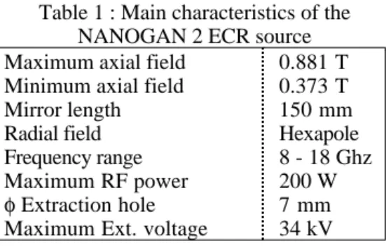
It consists of a graphite target, a compact ECR source (NANOGAN 2) [4] where the magnetic fields are produced by FeNdB permanent magnets and two front ends : high and low energy. All of these elements are installed in an heavily shielded casemate built at the underground level.
The primary beam hits a conical graphite target which is machined with slices 0.7 mm thick.
The target is designed such that its temperature increases up to nearly 2300°C when receiving the full beam power. This high temperature eases the evaporation of the radioactive ions from the graphite structure. The shape and dimensions of the target is designed in such a way that the temperature is as uniform as possible while the primary beam rotates at low frequency for a uniform distribution of the thermal power.
If the primary beam power decreases, an auxiliary ohmic heating allows to maintain the temperature of the target. The source itself is as simple as possible. It was already described many time (1). It consists principally in a cylindrical tube, 36 mm internal diameter, surrounded by the FeNdB permanent magnets.
Table 1 : Main characteristics of the NANOGAN 2 ECR source Maximum axial field
Minimum axial field Mirror length Radial field Frequency range Maximum RF power φ Extraction hole Maximum Ext. voltage
0.881 T 0.373 T 150 mm Hexapole 8 - 18 Ghz 200 W 7 mm 34 kV
The table 1 gives the most important characteristics of the source and the table 2 gives some intensities produced at the test bench with Argon.
Table 2 : Beam currents produced on test bench Ion Extracted beam (eµa) Ar8+ 143 Ar9+ 60 Ar11+ 10 Ar12+ 4 Ar13+ 1
An important feature of the production system is that, due to the rather high radiation level (several Sv) at the end of a production period (2 weeks at full power of the primary beam), the target and source assembly must be removed in a remote-controlled way.
Once the assembly is disconnected, a robot takes and put it in a 100mm thick lead container. A new assembly, previously carefully tested on a test bench is positioned in the same way.
As there could be a risk of contamination by radioactive dusts or gases, the primary beam input and the radioactive beam output are closed by double vacuum valves thus keeping the assembly under static vacuum during the transfer and storage.
The two front-ends cannot be disconnected remotely, but their disconnection was studied to be simple and rapid. They can be removed by the same robot. Fig. 1 shows a global view of the production casemate.
4 THE CYCLOTRON CIME
[
5
]
CIME is a room temperature, compact, medium energy cyclotron. The table 3 gives its main characteristics.
Table 3 : CIME overall characteristics
Min Max
Extraction energy (Mev/A) Injection energy (KeV/A) q/A RF frequency (Mhz) Harmonics Average B (T) 1.7 1.5 0.1 9.6 2 0.75 25 13 0.5 14.5 5 1.56
A first stable beam was injected in CIME on the last days of 1997 while the commissioning started really in last April.
4.1 The magnetic system
CIME is a compact cyclotron with two circular poles 3.5 m in diameter. Nevertheless, the magnet has a relatively original structure with 4 return yokes made of thick slabs. The magnetic circuit was built by CREUSOT LOIRE and SFAR and the coils were manufactured by SIGMAPHI (main coils) and SEF (correcting coils). The table 4 gives some characteristics of the magnet.
Table 4 : the CIME magnet Pole diameter
Extraction radius Average magnetic field Total steel weight Overall dimensions Max. excitation Turns/coil Pancakes/coil Trim coils
Number turns/Trim coil Max. total excitation
3.5 m 1.5 m 0.75 - 1.56 T 550 T 6.4 x 6.4 x 3.2 m 272000 At 168 7 11 sets 8 and 10 75600 At
The correcting coils are made of circular pancakes closed in a stainless steel, vacuum tight box. They are located between the pole face and the sectors.
All the magnetic calculations were made in 3D with TOSCA. The magnetic measurements took place in the spring 1997. They were done using a rotating arm with 93 hall probes 20 mm spaced in the acceleration zone and 10 mm in the extraction region. Measurements were firstly done without the extraction elements and later-on with the extraction channels installed. The results of the measurements were very near the calculations.
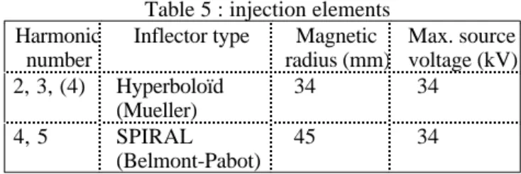
4.2 Injection
Injection of the beam is done axially, through the lower yoke and pole. Two different geometries are used depending on the harmonic number (table 5).
Table 5 : injection elements Harmonic
number
Inflector type Magnetic radius (mm) Max. source voltage (kV) 2, 3, (4) Hyperboloïd (Mueller) 34 34 4, 5 SPIRAL (Belmont-Pabot) 45 34
The geometry of the central region was studied with special care. The electromagnetic fields were calculated in the whole injection space and multiparticle programs allowed to simulate the behaviour of bunches of particles. The injection line allows to perfectly match the injected beam to the cyclotron acceptance. An injection efficiency higher than 50% (with buncher) is expected.
4.3 Acceleration
The beam is accelerated by two λ/4, cantilever dees with a maximum peak voltage of 80/100 kV. The main characteristics of the CIME RF system are given in table 6. Table 6 : RF characteristics Dee number Dee angle (°) Frequency range (Mhz) Accelerating gap (mm) Vertical dee aperture (mm) Max. peak voltage (kV) Max. surtension coefficient Q Coupling system 2 40 9.6-14.5 15 to 30 30 100 913 Adjustable loop The dee tips were carefully studied for injection. The angle is 60° for the first turns and 40° further. Posts help to get a better definition of the electric field in the first gaps.
4.4 Extraction
The beam is extracted at a mean radius of 1500 mm. Extraction is complete in less than half a turn. It is performed by one electrostatic deflector (splitted into two
parts) and two magneto-static channels. Position and electric field of the electrostatic channel can be adjusted while only the positions of the magnetic channels are adjustable. The table 7 gives some details on these elements.
Table 7 : Extraction elements
Electrostatic Magnetostatic Azimuthal extension Maximum field/gradient Free aperture 2 x 17° 70 kV/mm 14 mm 2 x 16° 5.5 and 13.3 T/m 32 mm
The magnetostatic channels were designed in order to minimize the perturbation of the field in the acceleration region. Nevertheless, in addition, image channels were added at 180° to suppress any possible first harmonic.
4.5 Vacuum system
Pumping in the vacuum chamber is mainly done by two cryopannels installed in one valley. A temperature of 20 °K is obtained in the inner panel by circulation of liquid hydrogen. The hydrogen is liquefied in heat exchangers feeded by 4 cryo-generators.
The pumping speed is of the order of 30000 l/s and the residual pressure is less than 5.10-8
mbar after half a day of pumping.
4.6 Diagnostics
Due to the very large intensity range of the beams which can be accelerated by CIME (103
to 1012
pps), two type of diagnostics are used [6] :
- Classical diagnostics including :
- A main radial, intercepting probe, with several fingers, covering the whole radial range.
- A set of central non intercepting phase probes. - A retractable plate in front of each magnetic channel.
- « Nuclear » type diagnostics :
- A plastic scintillator, followed by a photo multiplier is supported by the radial probe. It can be retracted behind the probe when the intensity is large.
- A silicon detector, installed in an other radial probe at 45° from the main one.
These detectors are sensitive to very low intensities (down to a few pps). They give a precise measurement of the phase and also, possibly of the energy.
On the other hand, the life-time of these diagnostics is limited, they are easily destroyed by an excess of beam and their useful range is limited as they do not deliver signal if the energy is too low.
5 PROPOSED METHOD FOR SETTING
THE CYCLOTRON
Adjust the cyclotron parameters directly with the radioactive beam is not suitable because :
- The intensity of the researched beam is usually very low and, most of the time, it is parasitized by beams of very near q/m which can be orders of magnitude more intenses.
- The production time of radioactive ions is limited by the life-time of the target, it is a precious time which cannot be used to set the machine.
The proposed method to set the machine and the beam line is in two steps :
1) Using the recorded data (field maps) and the simulation programs, a first set of parameters is determined.
2) A stable beam of very near q/m value of the radioactive one is produced and accelerated. This will allow to pretune the machine.
Once the radioactive beam will be produced by the source, its presence will firstly be controled by the identification station (mainly by gamma rays detection) then, the fine setting will be performed either by a ∆B or a ∆F variation. by putting ε =δ(q / m) (q / m) One gets : a) ε < few 10-4 δ f = 0 (δB B) CIME = −ε
The magnets of the beam lines have to be detuned by the same amount.
b) ε ≥ few 10-4
and < 10-2 δ
B= 0 δf= ε γmax
The settings of the beam line are not changed, the source voltage as well as the buncher must be returned
(δVs Vs = ε)
Whichever method will be used, we must always remember that the probably tiny radioactive beam will most of the time be accelerated simultaneously with much more intense parasitic beams, at least up to a certain radius.
6 PRESENT STATUS,
COMMISSIONING
Nearly all the items of SPIRAL are now installed and operational with the exception of the beam line at the output of the cyclotron which must be installed in the next summer.
Some auxiliary equipment to carry-off the used targets and sources and to store them have still to be built in the course of this year The air conditioning system including high efficiency filtering and the storage of the radioactive gases produced by the target are also designed and ready to be ordered.
The development and commissioning of the target and source assembly started a long time ago in a GANIL station specially devoted to these studies (SIRa). The GANIL beam power being limited at 400 W for these tests, complementary tests of the target were made at Louvain-la-Neuve with a 6 kW proton beam of 30 MeV.
These tests have allowed to predict the future production of radioactive ions by the source, at GANIL. The table 8 gives some typical values.
The commissioning of the low energy beam line and of CIME started in December 1997 with stable beam. Commissioning of the line was obvious and without any difficulty. A first beam (18
O4+
) was injected and accelerated in CIME up to nearly 10 MeV/u before Christmas 1997.
The tests restarted in April, after the GANIL winter shutdown. Two beams (18
O4+
, 16
O5+
) were tested at the same frequency and energy (10.4 Mhz, 10MeV/u) but at very
Table 8 : Typical production of radioactive beams Beam Source production (pps)
6 He 8 He 17 Ne 27 Ne 32 Ar 46 Ar 72 Kr 77 Kr 6.108 2.106 5.105 5.103 1.103 6.106 4.103 9.107
different magnetic fields (1T and 1.44T) with the same type of results :
. Very low energy beam line transmission : 80% for the nominal emittance (80πmm.mrad) in the first, analysing section and 92% in the rest of the line.
. Injection transmission into CIME 10% without bunching and 53% with the buncher « on », but still to be improved.
. Acceleration up to r = 1426 without losses and in good accordance with calculations.
. Complete and unexpected loss of beam at this radius, a few centimeters before the electrostatic deflector.
This unexpected difficulty is not yet clearly understood. Some localized magnetic perturbation (which could be caused by the structures added after the magnetic measurements) is suspected and several hypothesis are presently investigated (resonance, isochronism, median plane displacement ...)
7 CONCLUSIONS AND FUTURE
PLANS
As already said, SPIRAL Phase 1 will be completed at the end of the year and the first beams are expected in 1999.
In parallel, two important detectors for physics were approved : VAMOS : a large acceptance magnetic spectrometer and EXOGAM : a very efficient 4π gamma detector. These programs are supported by several European countries.
The demand for exotic beams being very large, we have already plans for future developments of SPIRAL.
The first step will certainly be the replacement of the ECR, multicharged ion source NANOGAN 2 by a much simpler source for one charge-state, followed by the capture
of the 1+ beam in a very efficient ECR source to get the necessary multicharged beam.
This process which was studied at the Institut des Sciences Nucléaires de Grenoble [7] for the PIAFE project would have several advantages.
a) Immediate access to the alcalin ions.
b) The 1+ source, can be smaller and less expensive than the NANOGAN 2 source, thus reducing the running costs.
This 1+→ n+ process is presently being studied in collaboration with Grenoble and a decision will be taken soon.
A second step will be the production of atoms by fission of heavy material like uranium. This process gives access to neutron rich isotopes, far from stability, which are very demanded. An European R and D program is already approved to explore this way. The proposed production method uses a deuteron primary beam stopped in a beryllium converter, the target itself follows the converter and receive the high neutron flux emitted. Experiments are already started in several places in Europe to determine the optimal parameters for this production.
8 ACKNOWLEDGMENTS
SPIRAL is funded by the region de Basse Normandie and by the French research agencies : CEA/DSM and
CNRS/IN2P3. In addition to the limited SPIRAL group many other colleagues from GANIL have contributed. The external French laboratories who are engaged in a collaboration work with SPIRAL (IPN Orsay, LNS Saclay, LPC Caen, SUBATECH Nantes, CEA/DAM Bruyères, ISN Grenoble ...) and the international scientific and technical committees are also important actors for the success of SPIRAL.
REFERENCES
[1] A. Joubert et al. « SPIRAL, a radioactive ion beam facility at GANIL » P.A.C. Washington, 1993 [2] M. Lieuvin et al. « Status of SPIRAL, the radioactive
ion beam project at GANIL » 14th Int. Cyclotron conf. Capetown, 1995
[3] A.C.C. Villari et al. « News from the SPIRAL project at GANIL » R.I.B. conf. Omiya, Japan, 1996
[4] L. Maunoury et al. « Nanogan II 14.5 Ghz... » Workshop on ECR ion sources, College Station, 1997 [5] M. Duval et al. « SPIRAL project : Status of the
cyclotron » Magnet technology, Pekin, 1997
[6] B. Laune et al. « The diagnostic system for the SPIRAL R.I.B. facility » 14th Int. Cyclotron conf. Capetown, 1995