Rb-stabilized laser at 1572 nm for CO
2monitoring
R Matthey, W Moreno, F Gruet, P Brochard, S Schilt and G Mileti Laboratoire Temps-Fréquence, Institut de Physique,Université de Neuchâtel, Neuchâtel, Switzerland E-mail: renaud.matthey-de-lendroit@unine.ch
Abstract. We have developed a compact rubidium-stabilized laser system to serve as optical
frequency reference in the 1.55-m wavelength region, in particular for CO2 monitoring at
1572 nm. The light of a fiber-pigtailed distributed feedback (DFB) laser emitting at 1560 nm is frequency-doubled and locked to a sub-Doppler rubidium transition at 780 nm using a 2-cm long vapor glass cell. Part of the DFB laser light is modulated with an electro-optical modula-tor enclosed in a Fabry-Perot cavity, generating an optical frequency comb with spectral cover-age extending from 1540 nm to 1580 nm. A second slave DFB laser emitting at 1572 nm and offset-locked to one line of the frequency comb shows a relative frequency stability of 1·10-11
at 1 s averaging time and <4·10-12 from 1 hour up to 3 days. 1. Introduction
Some applications require a frequency-stable laser source operating at a precise wavelength where no direct suitable molecular or atomic reference transition exists. A reason may be the weakness of the considered transition line-strength that would require long optical interaction length to ensure a suffi-cient absorption signal for laser stabilization. In other cases, the laser must precisely emit at a frequen-cy lying on the wing of an absorption line, at a detuning of up to several GHz from the line center, or even out of any absorption line. An example of such application is the measurement of the concentra-tion of carbon dioxide (CO2) in the atmosphere based on the integrated-path differential-absorption
lidar (IPDA) technique [1], as envisaged by space agencies [2] to identify on a global scale and more precisely the CO2 exchanges between the atmosphere and the Earth’s lands and oceans [3]. The
con-straints imposed on the lidar instrument for a CO2 mission were defined by feasibility studies [3, 4].
For a transmitter laser emitting at 1572 nm, on the slope of a CO2 absorption line, a frequency stability
– in terms of Allan deviation – below 20 kHz (<10-10 fractional frequency stability) is requested for
integration times from 700 s up to 3 years of mission operation time [5].
A relative frequency stability of about 3·10-11 was demonstrated by Numata et al. for integration
time up to 1,000 s at a wavelength of 1572.34 nm [6]. In this case, a distributed feedback (DFB) laser diode was frequency-stabilized at the center of a Doppler-broadened CO2 line using a multipass cell
with a path-length of 17 m combined with a laser frequency modulation technique. In the implemented approach, additional lasers could be offset-locked up to ± 7 GHz away from the master laser. Besides, compact 780-nm Rb-based frequency-stabilized laser heads were previously developed in our premis-es for atomic clocks, using DFB lasers and evacuated Rb cells with an optical path-length of a few centimeters only. These laser heads show a relative frequency stability better than 1·10-11 at all
time-scales between 1 s and 1 day [7]. The main goal of the present work consisted in transferring the high frequency stability achievable with an Rb cell to an arbitrary wavelength in the 1.55-m wavelength region, in particular around 1572 nm, for CO2 monitoring purpose.
8th Symposium on Frequency Standards and Metrology 2015 IOP Publishing
Journal of Physics: Conference Series 723 (2016) 012034 doi:10.1088/1742-6596/723/1/012034
Published in Journal of physics : Conference series 723, conf.1, 012034, 2016 which should be used for any reference to this work
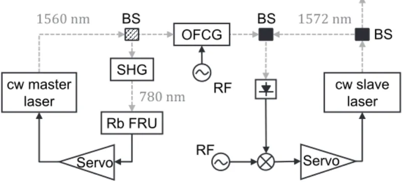
The laser system is illustrated in Figure 1. A fiber-pigtailed DFB laser emitting at 1560 nm (master laser) is frequency-doubled and stabilized to the D2 line of 87Rb at 780 nm. A part of the master laser
light is injected into an electro-optical modulator (EOM) enclosed in a Fabry-Perot cavity to generate an optical frequency comb (OFC). A second DFB laser emitting at 1572 nm (slave laser) is offset-locked to one line of the generated comb. The output of the system consists of a fraction of the stabi-lized slave laser light. The optical system is fully fibered.
Figure 1. Schematics of the laser system. Dashed grey lines and black lines correspond to optical fibers and electrical links, respectively. BS: beam splitter (hatched one: see text); OFCG: optical frequency comb generator; Rb FRU: rubidium frequency reference unit; RF: radio frequency oscillator; SHG: second harmonic generator. 2. Experimental Setup
2.1. Frequency Doubling for Stabilization at 1560 nm
The master laser is a fiber-pigtailed DFB laser (Emcore) emitting up to 80 mW of optical power at 1560 nm. The laser has a full width at half-maximum (FWHM) linewidth of 1-2 MHz (at 4-ms obser-vation time), determined using the concept of the β-separation line [8] from its measured frequency noise spectrum and also from the recorded beat note with two independent lasers. A fibered optical isolator is disposed at the output of the master laser to prevent unwanted feedback. A 50/50 polariza-tion-maintaining fiber beam splitter (PM-BS) splits the light into two outputs; the first one is used for frequency stabilization and the second to generate the OFC.
The first output of the PM-BS is frequency-doubled using a second harmonic generator (SHG) module made of a fiber-pigtailed 5-cm-long periodically-poled lithium niobate (PPLN) waveguide. The optimal operation temperature and the efficiency of the module were determined to be 50°C and 300 %/W (including the fiber coupling losses), respectively [9]. The frequency-doubled light is then injected into a frequency reference unit (FRU) that has a similar design as the one integrated in the laser heads described by Gruet et al. [7]. There, it optically pumps the 87Rb atoms (D
2 line, 780.24 nm)
contained in a home-built evacuated cylindrical cell (10-mm diameter by 19-mm length). The cell is thermalized and mounted in a magnetically-shielded package. The light is retro-reflected in order to probe the Rb vapor in a sub-Doppler absorption scheme that provides narrow resonances (~15 MHz FWHM) for frequency-locking.
Frequency-stabilization of the master laser is achieved by modulating its injection current with a 50-kHz sinusoidal signal and applying synchronous demodulation of the detected light intensity at the first harmonic of the modulation frequency. The correction signal obtained after a proportional-integrator servo-controller is applied to the laser current in a feedback loop.
2.2. Optical Frequency Comb Generation
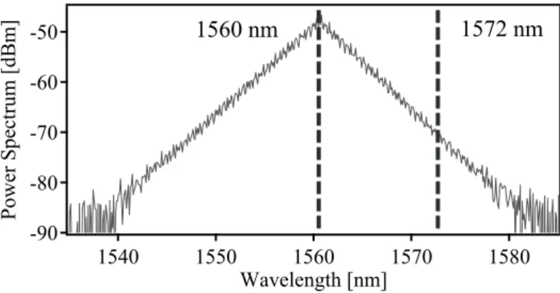
The frequency-stabilized master laser is used to seed an OFC generator (OptoComb). The injected light is phase-modulated by an EOM enclosed in a waveguide Fabry-Perot cavity with a finesse of 60 and a free spectral range of 2.5 GHz. The EOM is driven by a radio-frequency (RF) signal in reso-nance with the cavity at the forth harmonic of its free-spectral range, i.e., 10 GHz, to enhance the effi-ciency of the sideband generation process. Hence, a widely-spanning frequency comb is generated with a spectral coverage of 40 nm centred at the master laser frequency (Figure 2). The synthesizer generating the RF signal applied to the EOM is referenced to a hydrogen maser for long-term stability.
RF RF Rb FRU SHG cw slave laser cw master laser OFCG Servo Servo BS BS BS
8th Symposium on Frequency Standards and Metrology 2015 IOP Publishing
By denoting fm and M the RF and master laser frequency, respectively, the frequency of the nth-order
optical comb line, n , is given by n = M + n·fm , where n can take a positive or negative integer value.
As the frequency stability of the RF signal considerably exceeds that of the master laser,the frequency of all comb modes follows the fluctuations of the master laser. The frequency dithering applied to stabilize the master laser is thus also transferred to each mode of the frequency comb, which gives the possibility to offset-lock a slave laser to one mode of the comb without requiring any further frequen-cy modulation, e.g., of the slave laser.
Figure 2. Spectral envelope of the optical frequency comb cov-ering a span larger than 40 nm around the seed central line of 1560.48 nm, as obtained when driving the EOM at 10 GHz.
2.3. Offset-Locking for Stabilization at 1572 nm
For the slave laser, a linewidth of 1-2 MHz (FWHM) was determined in the same way as for the mas-ter laser. An optical isolator is disposed at the laser output and a 50/50 PM-BS divides the optical power into two parts. One part constitutes the optical output of the system, while the other is used to offset-lock the slave laser to one mode of the optical frequency comb using a similar method as pro-posed by Schilt et al. [10]. For this purpose, a fast photodiode detects the beat note between the slave laser and the nearest comb mode. After amplification, the beat signal is frequency down-converted by mixing with a local oscillator of frequency fLO referenced to the same hydrogen maser. The resulting
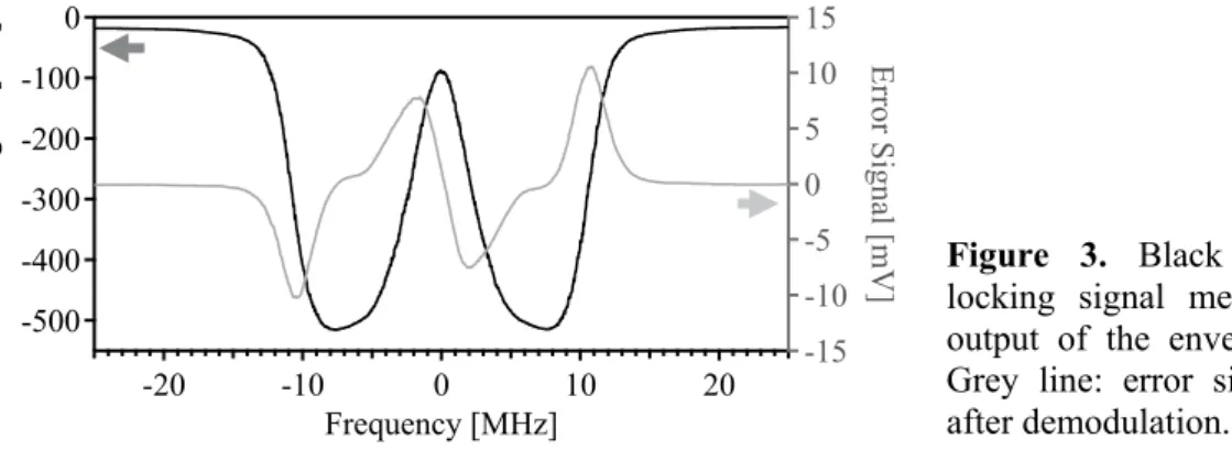
intermediate frequency signal is further filtered using the combination of a 1-MHz high-pass filter and an 11-MHz low-pass filter. Finally, an envelope detector measures the power of the transmitted RF signal, which, after demodulation at the master laser modulation frequency, provides a voltage error signal for an offset-locking stabilization loop [10]. The combination of the filters and envelope detec-tor acts as a frequency discriminadetec-tor and creates an absorption-like feature in the low-frequency elec-trical domain (see Figure 3). The frequency down-converted beat note between the slave laser and the comb line can thus be locked to the centre of this feature by generating a derivative-like signal using the dithering of the beat signal that results from the modulation of the master laser. The absence of dithering of the slave laser frequency is beneficial for the injection seeding process of the power oscil-lator of a lidar transmitter or to serve as an unmodulated optical frequency reference.
The comb line and the offset frequency are selected so that the slave laser emits at the desired fre-quency S = M + n·fm ± fLO. The sign of the offset frequency is determined from the observed change
in the injection current of the locked slave laser in response to a variation of the offset frequency fLO.
The mode number n can be determined when varying the EOM drive frequency fm or using an optical
spectrum analyser.
3. Frequency Stability Results
The frequency stability of the laser system was evaluated at the main stages of the setup, correspond-ing to different wavelengths, uscorrespond-ing heterodyne detection with external optical frequency references. Hence, we were able to follow how the stability of the Rb reference is transferred to the slave laser by successively evaluating the master laser before (1560 nm) and after (780 nm) the frequency-doubling process, an optical comb mode (1557 nm) and at last the slave laser (1572 nm).
-90 -80 -70 -60 -50 Power Spectrum [dBm] 1580 1570 1560 1550 1540 Wavelength [nm] 1572 nm 1560 nm
8th Symposium on Frequency Standards and Metrology 2015 IOP Publishing
Figure 3. Black line: offset-locking signal measured at the output of the envelope detector. Grey line: error signal obtained after demodulation.
3.1. Master Laser
The frequency stability of the master laser was measured at 1560 nm and 780 nm. At 1560 nm, a beat note was performed between the master laser locked onto the Rb direct F2→F’3 transition (which is the most stable at long term due to its lower temperature sensitivity [8]) and a self-referenced com-mercial Er-fiber comb fully stabilized to an H-maser. At 780 nm, the frequency-doubled master laser was heterodyned with an external Rb-stabilized reference laser head locked onto the cross-over CO22/23 transition, which demonstrated relative frequency stability better than 1·10−11 at all
time-scales from 1 s up to 1 day [7]. The measurements of the master laser at 780 nm and 1560 nm were carried out simultaneously – although they did not always have the same overall duration – and for two different types of fiber splitters at the laser output (hatched splitter in Figure 1).
Figure 4. Fractional frequency stability of the beat note between the master laser (1560 nm) and the self-referenced comb (■, ▲), and between the frequency-doubled master laser (780 nm) and an external Rb-stabilized reference laser head (●, ▼).
(■, ●), (▲, ▼): simultaneous measurement done with the first and second type of PM-BS, re-spectively.
As presented in Figure 4, a fractional frequency stability of 5.2·10-12 at 1-s averaging time
(corre-sponding to <1 kHz absolute instability at 1560 nm) is reached with the second type of fiber splitter. This value matches the estimated signal-to-noise limit at 1 s. Above 4,000 s, the long-term relative instability is always lower than 1·10-11 (2 kHz absolute frequency at 1560 nm). All stability measure-ments performed at 780 nm were limited by the resolution of the frequency counter, which type and settings differed from the ones used at 1560 nm. This effect is responsible for the difference observed at short term between the results at 780 nm and 1560 nm. The long-term fractional frequency stability at 780 nm is also further limited slightly below 1·10-11 by the reference laser head for integration times longer than 104 s.
The first type of fiber splitter induced spurious reflections and associated etalon fringes that de-graded the short-term stability at the level of 1·10-10 at 5 s. The replacement of this low-performing splitter with a better one (type 2 in Figure 4) drastically improved the short-term stability by more than an order of magnitude. With the second type of splitter a previously hidden instability bump reaching 3·10-11 at around 100-s integration time is observed. It is caused by the presence of a fiber splice at the
output of the frequency-doubling module that induces etalon interferences. -500 -400 -300 -200 -100 0
Offset Lock Signal [mV]
-20 -10 0 10 20 Frequency [MHz] -15 -10 -5 0 5 10 15 E rro r S ig nal [ m V ] 10-12 10-11 10-10 10-9 10-8
Overlapping Allan Deviation 100
101 102 103 104 105 Integration Time [s] 780 nm - PM-BS type 1 1560 nm - PM-BS type 1 780 nm - PM-BS type 2 1560 nm - PM-BS type 2 Target for CO2 detection
S/N limit
8th Symposium on Frequency Standards and Metrology 2015 IOP Publishing
3.2. Optical Frequency Comb
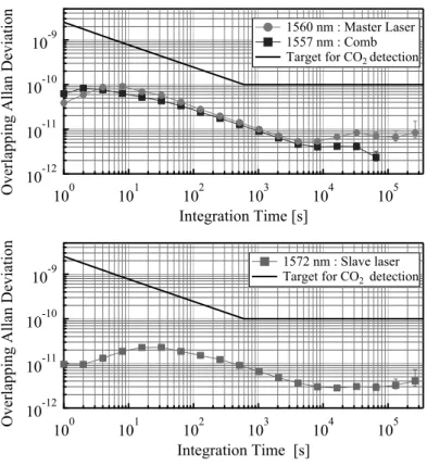
When the first type of splitter was installed to split the emission of the master laser, the frequency stability of the generated OFC was retrieved from the beat-note frequency measured between one line of the comb and a narrow-linewidth (<10 kHz) auxiliary semiconductor laser operating at 1557 nm. The laser was phase-locked to the self-referenced comb to ensure its long-term frequency stability. The low optical power per mode in the two combs prevented the direct beating of the generated OFC against the self-referenced comb. As shown in Figure 5, the stability of the OFC line at 1557 nm faith-fully reproduces the master laser stability at 1560 nm – already presented in Figure 4 but replicated for comparison purpose. The non-concomitance of both measurements results in slight short- and mid-term differences due to modified temperature-induced etalon fringes in the master laser locking loop, and in variations in the long term due to the slowly fluctuating laboratory background temperature.
Figure 5. Fractional frequency stability of the beat note between one line of the OFC and a 1557-nm auxiliary laser, phase-locked to a self-referenced comb (■), and between the master laser and the self-referenced comb (●). Meas-urements were not carried out simultaneously.
Figure 6. Fractional frequency stability of the beat note between the slave laser at 1572 nm and the self-referenced comb (■).
3.3. Slave Laser
In the same manner as applied to the master laser, the frequency stability of the slave laser was deter-mined from the beat note with the self-referenced comb fully-stabilized to the H-maser. The offset frequency fLO in the slave laser stabilization loop was set to 50 MHz and the drive frequency of the
OFC generator was chosen so that the slave laser was lying at the center of the CO2 R20 absorption
line (190,743,066.5 MHz). To properly stabilize the slave laser, the modulation amplitude of the mas-ter laser, still locked to the direct transition F2→F’3 with the fiber splitmas-ter of the second type, was increased, implying a degradation of the short-term stability of the slave laser with respect to the mas-ter laser stability previously reported in Figure 4.
The obtained fractional frequency stability of the slave laser is displayed in Figure 6. It amounts to 1·10-11 at 1 s and stays below 2.5·10-11 for all timescales up to the maximum assessed integration time of 3 days, reaching 4·10-12 on the long term. The target stability for atmospheric CO2 monitoring is by
far fulfilled. The measurement was performed under environmental temperature conditions that were different from those prevailing for the evaluation of the master laser stability (see Figure 4). The setup was less protected against rapid temperature changes, which made the temporal frequency fluctuations linked to etalon-like cavity more severe. This resulted in a shift of the instability bump in the Allan deviation towards shorter integration times (~30 s).
10-12
10-11
10-10
10-9
Overlapping Allan Deviation 100
101 102 103 104 105
Integration Time [s]
1560 nm : Master Laser 1557 nm : Comb
Target for CO2 detection
10-12
10-11
10-10
10-9
Overlapping Allan Deviation 100
101 102 103 104 105
Integration Time [s]
1572 nm : Slave laser
Target for CO2 detection
8th Symposium on Frequency Standards and Metrology 2015 IOP Publishing
4. Discussion and Perspective
For the demonstration of the developed scheme, an H-maser was employed as a frequency reference for the OFC generator driving signal as well as for the offset-locking frequency. Both RFs can be ref-erenced to a more compact and transportable frequency reference such as a commercially-available GPS-referenced Rb atomic clock that offers a sufficient stability compatible with the RF requirements of the system (fractional frequency stability of 1·10-9). Depending on the desired output wavelength,
the mixer and RF oscillator of the offset-locking loop might be omitted, locking the slave laser directly to the optical comb and fine-tuning its frequency with the OFC generator modulation frequency.
The accuracy and stability of the output frequency at 1572 nm are most of all dictated by the per-formance of the master laser as the RF sources used in the setup are much more stable. The accuracy and reproducibility of the master laser frequency, which depend on the selected reference sub-Doppler Rb line and on the frequency stabilization method, are presently being investigated. Our preliminary results suggest that for the direct F2→F’3 transition an accuracy below 100 kHz and a reproducibility of 20 kHz could be reached with a relatively simple and compact rubidium cell setup, in accordance with the results of Ye et al. [11].
At present, an imperfection in the fiber at the frequency-doubling module output that induces eta-lon-like cavities limits the frequency stability of our system between 10-s and 100-s integration time. The reduction of these etalon-like effects should decrease the short-term instability down to the esti-mated signal-to-noise limit of the master laser (5.2·10-12 τ-1/2).
5. Conclusion
We have demonstrated that the stability of a DFB laser emitting at 1560 nm, stabilized to rubidium using frequency-doubling and sub-Doppler spectroscopy, can be transferred through the generation of an optical frequency comb and a frequency offset-locking scheme to a second DFB laser emitting at 1572 nm. The relative frequency stability of the master laser is 5.2·10-12 at 1 s, at the limit of the
sig-nal-to-noise. At 1572 nm, a relative frequency stability of 1·10-11 at 1 s has been obtained, and lower
than 2.5·10-11 for all assessed timescales (1 s to 3 days), reaching 4·10-12 above 3,000 s. Such result
fulfils the requirements for a CO2 satellite lidar mission. The applied method is not restricted to
1572 nm and can be implemented for any wavelength located within the comb span. 6. Acknowledgement
This work was supported by the European Space Agency and the Swiss National Science Foundation (project number 156621). We thank our colleague Dr. Christoph Affolderbach and Dr. Andreas Fix (DLR, Germany) for helpful discussions.
References
[1] Ehret G, Kiemle C, Wirth M, Amediek A, Fix A and Houweling S 2008 Appl. Phys. B 90, 593 [2] ESA 2008 Report for Assessment, SP-1313/1
[3] Bréon F M and Ciais P 2009 Comput. Geosci. 342 412
[4] Caron J, Durand Y, Bezy J L and Meynart R 2009 Proc. Lidar Technologies Techniques and
Measurements for Atmospheric Remote Sensing V (SPIE, 2009), paper 74790E
[5] Fix A, Matthey R, Amediek A, Ehret G, Gruet F, Kiemle C, Klein V, Mileti G, Pereira do Carmo J and Quatrevalet M 2014 Proc. Int. Conf. on Space Optics (Tenerife), session 2C [6] Numata K, Chen J, Wu S, Abshire J and Krainak M 2011 Appl. Opt. 50 1047
[7] Gruet F, Pellaton M, Affolderbach C, Bandi T, Matthey R and Mileti G 2012 Proc. of the Int.
Conf. in Space Optics (Ajaccio), paper 048
[8] Di Domenico G, Schilt S and Thomann P 2010 Appl. Opt. 49 4801 [9] Matthey R, Gruet F, Schilt S and Mileti G 2015 Opt. Lett. 40 2576
[10] Schilt S, Matthey R, Kauffmann D, Affolderbach C, Mileti G and Thévenaz L 2008 Appl. Opt. 47, 4336
[11] Ye J, Swartz S, Jungner P and Hall J 1996 Opt. Lett. 21 1280
8th Symposium on Frequency Standards and Metrology 2015 IOP Publishing