HAL Id: tel-03205970
https://tel.archives-ouvertes.fr/tel-03205970
Submitted on 22 Apr 2021
HAL is a multi-disciplinary open access
archive for the deposit and dissemination of sci-entific research documents, whether they are pub-lished or not. The documents may come from teaching and research institutions in France or abroad, or from public or private research centers.
L’archive ouverte pluridisciplinaire HAL, est destinée au dépôt et à la diffusion de documents scientifiques de niveau recherche, publiés ou non, émanant des établissements d’enseignement et de recherche français ou étrangers, des laboratoires publics ou privés.
UWB based Secure Ranging and Localization
Baptiste Pestourie
To cite this version:
Baptiste Pestourie. UWB based Secure Ranging and Localization. Micro and nanotechnolo-gies/Microelectronics. Université Grenoble Alpes [2020-..], 2020. English. �NNT : 2020GRALT067�. �tel-03205970�
THÈSE
Pour obtenir le grade de
DOCTEUR DE L’UNIVERSITE GRENOBLE ALPES
Spécialité : NENT
Arrêté ministériel : 25 mai 2016
Présentée par
Baptiste Pestourie
Thèse dirigée par Vincent BEROULLE, Professeur des
Universités, LCIS
Co-encadrée par Nicolas FOURTY, Maître de Conférence,
LCIS
préparée au sein du Laboratoire LCIS dans l'École Doctoral EEATS
UWB Secure Ranging and
Localization
Thèse soutenue publiquement le 04.12.2020, devant le jury composé de :
François Spies
PR Université de Franche-Comté, Président Adrien Van den Bossche
MCF HDR Université Toulouse 2, Rapporteur Aurélien Francillon
PR Eurecom, Rapporteur Assia Tria
Ingénieur HDR CEA Grenoble, Examinatrice Vincent Beroulle
Introduction
__________________________________________________________________________________
2
Abstract
Location services are foreseen as one of the major IoT features in the next years, and have gained a lot of interest over the last decade from the literature of Wireless Sensors Networks, (WSN) and Vehicular Ad Hoc Networks (VANet). Impulse-Radio Ultra-Wideband (UWB), standardized in IEEE 802.15.4-2003, is currently the most performant radio positioning technology with centimeter-level accuracy and is used widely in industrial applications. It has been proven in the literature that UWB positioning is not completely tamper-proof, as various physical and link layers vulnerabilities have been identified in 802.15.4. Most of the major attacks against IR-UWB are physical-level attacks, such as Early-Detection/Late-Commit (ED/LC). Considering their cost, complexity, and sometimes lack of maturity, they are not necessarily the most realistic attacks against cheap IoT systems. On the other hand, protocol-level flaws expose IR-UWB positioning against attacks that can be mounted with limited expertise and cheap hardware. Hence, the aim of this work is to identify the most critical vulnerabilities of 802.15.4 IR-UWB, evaluate real-world attacks against UWB IPS and propose low-cost countermeasures suitable for IoT applications. An open platform for IR-UWB positioning security evaluation, SecureLoc, is part of the contributions. We propose and evaluate various spoofed acknowledgment-based attack schemes against IR-UWB. Several countermeasures, at the physical, medium access control and system level, are proposed, including notably a novel weak PUF-based authentication protocol, a spoofing resilient acknowledgment scheme, a tamper-proof ranging approach, and a cooperative verification protocol for rogue node detection. All the proposed attacks and countermeasures have been implemented and evaluated on SecureLoc.
Introduction
__________________________________________________________________________________
3
Résumé
Les services de localisation sont considérés comme une des fonctionnalités majeures de l’IoT dans les prochaines années, et font l’objet d’un intérêt croissant dans la littérature des réseaux de capteurs sans fil (Wireless Sensors Network (WSN)). La technologie IR-UWB (Impulse-Radio Ultra-Wideband), standardisée dans IEEE 802.15.4, est actuellement la technologie de localisation la plus performante avec une précision de l’ordre du centimètre et est largement déployée dans des applications industrielles. Il a été démontré dans la littérature que la localisation UWB n’est pas immunisée contre la falsification (tampering) ; plusieurs vulnérabilités au niveau des couches physiques et liaison de données ont été identifiées dans des travaux précédents. La plupart des attaques majeures contre l’UWB sont des attaques physiques, telles que les attaques Early-Detection/Late-commit (ED-LC). Du fait de leur coût et complexité, parfois doublé par un manque de maturité technologique, elles ne sont pas nécessairement les menaces les plus réalistes dans un contexte IoT. En revanche, des failles protocolaires au niveau de la couche liaison de données exposent l’IR-UWB à des attaques nécessitant peu d’expertise et de matériel. Par conséquent, les travaux introduits dans ce manuscrit sont consacrés à l’identification des menaces les plus critiques contre la technologie 802.15.4 IR-UWB, à évaluer des attaques contre cette technologie en conditions réelles, et à proposer des contremesures à bas coût appropriées à des applications IoT. Une plateforme dédiée à la localisation IR-UWB, SecureLoc, fait partie des contributions. Plusieurs attaques à base d’acquittements frauduleux sont proposées et évaluées. Diverses contremesures sont proposées, au niveau des couches physiques, liaison de données et système, incluant notamment un protocole d’authentification physique basé sur un weak
PUF, une technique d’acquittement résistante contre les usurpations d’identité, un protocole
d’estimation de distance (ranging) immune contre la falsification de position et un protocole coopératif de détection des nœuds malicieux. Toutes les attaques et contre-mesures proposées ont été implémentées et évaluées sur la plateforme SecureLoc.
Introduction
__________________________________________________________________________________
4
Acknowledgment
I am grateful to Vincent and Nicolas for their supervision throughout my PhD. Our collaboration was very enjoyable thanks to their advices and guidance. I would also like to thank Cyril for his long-standing friendship and his comments on the manuscript, Louise and my family for their continuous support, and my LCIS colleagues for the good moments spent together.
This work has been supported by the grants provided by IDEX IRS (Initiatives de
Introduction
__________________________________________________________________________________
5
Chapter I
Introduction
The need for spatial tracking in industrial environments or public facilities has been leading the growth of indoor positioning solutions for over two decades. Manufacturing and supply chain supervision, indoor drone navigation or goods tracking in warehouse are part of the non-exhaustive list of applications benefiting from indoor positioning solutions. Historically, the Global Positioning System (GPS) is the most widely known positioning technology and is now used by the general public on a weekly basis. However, GPS does not deal with Line-of-Sight obstruction, which automatically occurs in indoor environments, and lacks robustness against multipath effects. Considering that, new solutions had to emerge regarding indoor localization, as GPS does not provide satisfying enough performances and reliability when it comes to the aforementioned applications. Positioning technologies have existed for about a century, with the introduction of the Sound Navigation Ranging (Sonar) [1] and RAdio Detection And Ranging (Radar) [2], but their cost and limitations have prevented them from being implemented in public facilities or factories until recently. Among the various technological solutions developed for indoor positioning, radio-based solutions have gained a lot of interest from the literature in the early 2000s, considering their low cost and relatively easy integration in buildings. Electromagnetic signals can be exploited for positioning, as their attenuation, phase or time-of-flight convey information about the distance traveled by the signal or its angle of arrival. This principle was already used for the first Radar prototypes in the 1930s, but the recent growth of the Internet of Thing (IoT) is leading the expansion of cheap radio transceivers in all sorts of applications, enabling low-cost integration of tracking features [3]. Many research works have been conducted on developing indoor positioning systems based on the most popular radio standards; the challenge was to reach sufficient accuracy and reliability to be functional. Solutions based on Bluetooth or WiFi can typically reach meter-level accuracy and a localization rate up to 10 Hz [4], but this is not enough for some applications, such as drone navigation. The release of the 3.1 ~ 10.6 GHz bands by the Federal Communications Commission (FCC) in 2002 was a game changer, leading to the introduction of Ultra-wideband (UWB) technologies. Two different standards have defined UWB specifications; IEEE 802.15.3 [5], designed for high-throughput, and IEEE 802.15.4 [6], designed for accurate ranging and positioning. 802.15.3 UWB was primarily intended for wireless USB and wireless HDMI, which used to be considered as very promising back in 2010, but ended up falling apart in favor of USB-C and are now very marginal technologies. On the other hand, Impulse Radio Ultra-wideband (IR-UWB), defined in IEEE 802.15.4, is based on very short pulses (2 ns width) allowing accurate time of flight ranging with an typical accuracy of about 10 cm and localization rates going up to 1000 Hz. Due to the large bandwidth used (at least 500 MHz), 802.15.4 IR-UWB is robust against multipath effects and provides an accurate and reliable solution for indoor positioning applications. An amendment for additional physical layer specifications, IEEE 802.15.4a, has been defined in 2007, and merged into 802.15.4 in
Introduction
__________________________________________________________________________________
6
2011. Further enhancements have been brought in 2015 in IEEE 802.15.4f. Currently, the leading manufacturer on the market is Decawave, and their popular IR-UWB transceiver, the DW1000 [7], is based on 802.15.4a. Hence, the majority of UWB IPS is currently based on implementations of 802.15.4a and actual implementations of 802.15.4f are not widespread on the market as far as we are aware.
IR-UWB did not really reach a broad success until very recently. Although it is used in specific and exigent positioning applications, the fact that IR-UWB, contrary to its competitors, was not already integrated in popular IoT products was a hindrance to its growth. One of the motivations for the interest towards radio-based is indeed that the positioning features can be integrated into existing radio devices, which are primarily used for communication purposes. Despite featuring low power consumption and high throughput, IR-UWB has never been broadly integrated in general public IoT products, partially due to the cost of IR-UWB transceivers being 3 to 5 times higher than Bluetooth or WiFi transceivers. However, IR-UWB remains the leading radio solution for demanding industrial applications or indoor navigation, considering that it largely outperforms its radio competitors. Moreover, one of the powerful assets provided by IR-UWB is its inherent security when it comes to the integrity of the positions measured.
The physical layer defined for UWB-IR in IEEE 802.15.4 has indeed the particularity to support time-of-flight ranging, which is typically not possible on other radio standards due to the extremely small time granularity required. Electromagnetic signals travel nearly at the speed of light, which means that typical times-of-flight in indoor environments lie in the order of magnitude of a few nanoseconds. The modulation techniques used by most radio standards, along with other factors, do typically not allow reaching such granularity, whereas the impulse-based nature of IR-UWB leads to sub-nanosecond accuracy [6]. Due to that limitation, conventional radio positioning approaches use either the phase or the attenuation of a signal as their indicator for distance estimation, but these parameters can be potentially replicated and tampered by an attacker, by simply repeating or relaying a frame with specific physical parameters. On the other hand, considering that it is not possible to exceed the speed-of-light, reducing the time-of-flight of a signal in order to appear closer is not physically possible. As a consequence, the inherent principle of time-of-flight ranging mitigates attacks against proximity-based systems, and can easily unveil attempts to replay or relay attacks as these attacks typically induce delays much higher than the time-of-flight itself. These considerations concern the physical layer, and integrity protection can only be granted if proper security mechanisms are implemented at higher levels as well.
The potential of IR-UWB for secure positioning has recently attracted interest from several manufacturers, leading to the creation of the IEEE 4z group task in January 2019 and the Fine Ranging (FiRa) consortium in July of the same year. The 4z amendment [8] aims to improve even further the ranging performances of IR-UWB and the security of the physical layer, with companies such as Apple, NXP or Decawave involved. The FiRa consortium is “dedicated to the development and widespread adoption of seamless user experiences using the secured fine ranging and positioning capabilities of interoperable Ultra-Wideband
Introduction
__________________________________________________________________________________
7
(UWB) technologies” [9]. IR-UWB meets a growing success and is now starting to reach the general public market; the iPhone 11 Pro, launched by Apple in August 2019, was the first smartphone to embed a UWB chip. The pandemic situation created by Covid-19 has considerably highlighted the need for more accurate ranging and positioning features on smartphones, as the development of social distancing applications has suffered from the limited performances of Bluetooth-based ranging. Major actors of the Information Technology (IT) industry have expressed their interest in IR-UWB in the first semester of 2020, and the technology is expected to be widely integrated in consumer electronics products and notably smartphones by the next two or three years [10].
As of July 2020, the transition to 4z is still on-going. The very first 4z IR-UWB transceivers have recently started to get released, and the 4z group task is still working on the amendment specifications. The majority of IR-UWB IPS are currently based on 802.15.4a, and given that the 4z guarantees retro-compliance, 4a and 4z devices will most likely have to interoperate in the next years. The work introduced in the manuscript is mostly based on the 802.15.4a standard; the impact of the transition to 4z on the presented results will be discussed in the conclusion.
The security assets brought by the time-of-flight approach on 802.15.4a IR-UWB are not vulnerability-free. Considering that IR-UWB IPS are often tracking expensive equipment (e.g., drones, forklifts), security flaws can lead to significant damages and even sometimes to human harm. Previous works have contributed to identifying the security flaws of 802.15.4a UWB, and in some cases proposed actual attacks based on these vulnerabilities. The major attacks proposed in the literature are physical attacks, which typically allow to fool a receiver into measuring an incorrect timestamp. Early-Detection/Late-Commit attacks (ED-LC) [11] in particular, which can be described briefly as a “relay backward in time” type of attack, are currently considered as one of the most significant attacks against this technology1. While
being technically advanced and able to bypass all the security mechanisms defined in 802.15.4, ED-LC and other physical attacks proposed in the literature have been demonstrated, as far as we are aware, only in simulation environments. Also, their impact has been evaluated mostly from a peer-to-peer ranging perspective. Indoor Positioning Systems require multiple reference stations to work properly, which means that a malicious node has to be able to tamper not one but all the reference stations when mounting an attack. To remain stealthy when doing so, the malicious node must preserve the cohesiveness between the responses of the different reference stations, which is a challenging task. This induces an extra layer of complexity for an attacker compared to tampering the ranging protocols of a single station. Although countermeasures have been proposed for most of the identified vulnerabilities, these countermeasures are often only functional against the specific flaw they aim to address, are not costless in terms of hardware and computational load, and often involve link or physical layer modifications to the standard. They aim to secure the ranging protocol, i.e., the distance estimation in a peer-to-peer protocol. Yet, IPS
Introduction
__________________________________________________________________________________
8
always involve multiple stations, and the redundancy and cohesiveness between the reference stations can be exploited to build high-level countermeasures even if the integrity of ranging protocols cannot be guaranteed.
Based on this consideration, a fair amount of research works based on system-level approaches [4] for secure positioning has emerged in the literature of Wireless Sensors Networks (WSN) in the last fifteen years. Although some of these approaches are specific to a given technology, a significant effort has been made to propose high-level countermeasures regardless of the particular radio technology used on the IPS. One of the interesting properties of some of these approaches is that they are not only effective against attacks held by a third-party (external attack), but also against nodes that are legitimately part of the network and lie on their position (internal attacks). Indeed, 802.15.4 IR-UWB positioning is based on the assumption of honest participation of the nodes in ranging protocols, and is not more immune than other technologies against internal attacks, which are challenging to detect. Existing countermeasures against internal attacks, including system-level countermeasures, require often specific hardware to be functional (e.g., directive antennas or specific transceiver designs) and are not costless.
One of the main issues regarding the current state-of-the-art of secure positioning on IR-UWB is the lack of real-world experimentations and results when it comes to the proposed attacks and countermeasures. We already mentioned that the major physical attacks proposed in the literature have not been demonstrated outside a simulation environment. Their requirements, arguably in terms of cost and notably in terms of technical complexity, are fairly high. Their capability to produce coherent positions against an actual IPS remains to be studied. Regarding countermeasures, system-level approaches are promising in terms of flexibility, cost and portability, yet they are also rarely studied in real-world environments and mostly demonstrated through simulation or strictly analytically.
Ultimately, the goal of any position tampering attack, no matter if it is mounted internally or externally, is to fool the IPS into thinking that the measured position is legit. This mostly depends on the capability to produce tampered distances than are close enough in terms of stability and mutual agreement between the reference stations to distances obtained in non-adversarial conditions. Proper benchmarks are needed to evaluate that, especially considering that any localization algorithm deals with natural inconsistencies due to the measurement noise. Based on that consideration, we have built an open testbed for secure positioning, SecureLoc. Since off-the-shelf IR-UWB positioning systems do not give access to all the layers, SecureLoc provides an open-source testbed for secure positioning experiments. The motivation is to allow the evaluation of attacks and countermeasures in a real-world IR-UWB IPS, with full access to the layers involved in the localization process. Based on the localization experiments on SecureLoc and on an analysis of the security model of a typical UWB IPS, we propose an EBIOS [12]–based vulnerability analysis. We highlight through this vulnerability analysis that the absence of cryptography on the acknowledgment defined in 802.15.4a is currently one of the most critical vulnerabilities of IR-UWB, due to the acknowledgments being used in the ranging protocols recommended in the standard. This
Introduction
__________________________________________________________________________________
9
vulnerability is well-known, and it has been suggested several times in the literature that it could be simply addressed by replacing acknowledgments by other types of frames supporting integrity protection in ranging protocols. Exploiting the acknowledgment vulnerability to build distance tampering attacks has often been considered as trivial, and has never been studied more in-depth to our knowledge. Yet, we demonstrate that due to the very small time granularity involved, the basic forged acknowledgment attacks suggested in the literature are far from trivial and mildly effective. We demonstrate how the effectiveness of these attacks can be enhanced, before proceeding to propose countermeasures that do not involve acknowledgment replacement in the ranging protocols or additional cryptographic operations. Finally, we propose system-level countermeasures that can detect internal attacks without requiring any dedicated hardware, along with contributions at the physical level regarding node authentication and key establishment. A more detailed list of the contributions is given chapter by chapter in the following.
The history of the evolution of positioning technologies is briefly covered in Chapter II, followed by a comparison of the localization performances of the major radio technologies. A particular focus is given on the 802.15.4 IR-UWB specifications, including its built-in security mechanisms. The most significant system-level approaches for secure positioning are introduced and classified.
SecureLoc platform is introduced in Chapter III. We show the benefits of SecureLoc as a testbed for secure positioning experiments on IR-UWB through a description of the platform architecture and functionalities. We evaluate localization performance benchmarks in non-adversarial settings with state-of-the-art localization approaches, to later evaluate the capabilities of attacks to produce tampered positions that are realistic. For that purpose, three detection factors are defined, based on the redundancy, consistency and plausibility of the distances measured. Each of these factors is evaluated in non-adversarial settings, such as defining thresholds for attack detection.
A vulnerability analysis of 802.15.4 IR-UWB indoor positioning is proposed in Chapter IV. We report the vulnerabilities of IR-UWB positioning and related attacks that have been identified in the literature. We evaluate their severity and likelihood based on the guidelines proposed by the French National Agency of Cybersecurity (ANSSI) in the risk manager method EBIOS [12]. Our analysis is held from the perspective of a typical industrial indoor positioning system. We discuss the most critical attacks identified.
The attacks implemented on the platform are presented in Chapter V. We first introduce an internal attack approach. Then, we propose several attack schemes based on spoofed acknowledgments. We demonstrate that the basic exploit of the acknowledgment vulnerability suggested in the literature is only effective when acknowledgments are tightly scheduled by the victim node. When acknowledgments are not scheduled, we demonstrate analytically and experimentally that basic spoofed acknowledgments attacks produce very erratic results due to the variability of the reply time. Two enhanced attack schemes are proposed, which combine forged acknowledgment with targeted jamming attacks and relay attacks. We show that these schemes allow the attacker to get finer control over the distances
Introduction
__________________________________________________________________________________
10
obtained. When acknowledgments are tightly scheduled, we demonstrate that the attack can be extended to the whole positioning system and let the attacker take control over the victim node’s position with high accuracy.
Several countermeasures are proposed in Chapter VI. We first propose to address the acknowledgment vulnerability without any additional cryptographic operation, with an approach based on randomized reply time. Then, we present two system-level countermeasures that aim to prevent from both external and internal attacks. The first one is based on a differential ranging approach, and the second one on a cooperative protocol. Finally, we introduce several interesting results at the physical layer regarding node authentication and key establishment. We demonstrate that clock skew on UWB devices has properties that are unique to each manufactured chip, similarly to a Physically Unclonable Function (PUF) [13], and propose an authentication protocol based on these properties. A Channel-Based Key Extraction (CBKE) approach based on first path power is proposed, which can be integrated within the proposed authentication protocol. By exploiting the randomness and reciprocity of wireless channels, these approaches allows two nodes to establish a secret key without using asymmetric cryptographic primitives.
Lastly, we conclude in the last chapter and discuss the perspectives related to the major contributions in this work. We give some insights on the impact of the transition to 4z on this work.
Introduction __________________________________________________________________________________
11
Contents
Chapter I Introduction ... 5 Chapter II Context ... 12II.1 Radio-based Indoor Positioning ... 13
II.2 Security of radio Indoor Positioning Systems ... 39
Chapter III SecureLoc Platform... 46
III.1 Motivation ... 47
III.2 SecureLoc Architecture ... 48
III.3 Benchmarking the performances at each layer ... 52
III.4 Approach and threat model ... 66
Chapter IV Vulnerability Analysis of 802.15.4 IR-UWB Indoor Positioning Systems .. 72
IV.1 Overview ... 73
IV.2 Attack Vectors ... 84
IV.3 Conclusion: most critical attacks ... 92
Chapter V Attacks against 802.15.4 IR-UWB Indoor Positioning Systems ... 93
V.1 Internal attacks ... 94
V.2 Spoofed acknowledgment attacks ... 95
Chapter VI Countermeasures for IR-UWB Indoor Positioning Systems ... 115
VI.1 Countermeasures against the acknowledgment vulnerability ... 117
VI.2 System-level Countermeasures ... 126
VI.3 A clock-skew based authentication protocol ... 147
VI.4 Channel-based Key Extraction ... 159
Context
__________________________________________________________________________________
12
Chapter II
Context
We introduce in this chapter the state-of-the-art of Indoor Positioning Systems (IPS) and their security. We first go through the history behind the emergence of modern IPS, and show how modern positioning techniques are derived from historical technologies. Radio-based IPSs have demonstrated a promising potential over the last fifteen years for IoT applications; we discuss the core principles of radio positioning techniques and compare several popular radio technologies on their cost and performances. In particular, we introduce in detail 802.15.4 IR-UWB, which is currently by far the most performant radio positioning technology. Finally, we discuss the main aspects of radio IPS security; general attack schemes against these systems are introduced along with the major high-level countermeasures proposed in the literature.
Chapter contents
II.1 Radio-based Indoor Positioning ... 13
II.1.1 General Context ... 13
II.1.2 Ranging principles on radio Indoor Positioning Systems ... 15
II.1.3 Comparison of radio positioning technologies ... 18
II.1.4 Positioning algorithms ... 21
II.1.5 802.15.4 UWB, a technology tailored for Indoor Positioning ... 28
II.2 Security of radio Indoor Positioning Systems ... 39
II.2.1 General attack schemes against Indoor Positioning Systems... 39
Context
__________________________________________________________________________________
13
II.1
Radio-based Indoor Positioning
II.1.1 General Context
Positioning an object in a 2D or 3D space is intrinsically related to the capability of measuring distances between two points. The first instances of technologies able to estimate distances remotely came in the 20th century, with the invention of Sound Navigation Ranging
(Sonar) [1] and RAdio Detection And Ranging (Radar)[2]. With the imminent World War I, these new devices were oriented towards military navigation. These two technologies are both able to estimate the distance to the first obstacle in a straight Line-of-Sight1 by using the
reflection of a signal (or echo) on this obstacle. However, they differ by the nature of the signal used for this purpose: sonar is based on acoustic waves for the sonar whereas radar uses radio waves. Sonar exploits the propagation of sound in water to estimate the distance and is most effective in immersion. Sonar was indeed conceived for submarines and vessels. Radar on the other hand is effective in the atmosphere and has been widely used for vessels and airplanes detection.
Another major difference between these two technologies is how the signal is processed. Sound propagated at a speed of roughly 1500 m/s in water, which is low enough to measure with reasonable accuracy the signal travel time. On the other hand, radio waves travel in the air nearly at the speed of light, i.e., approximately 300 000 km/s, and estimating the time-of-flight of a signal is much more challenging given its order of magnitude. This challenge was overcome a few years before WWII as several countries developed independently their own prototypes. The foundation of the radar is based on a transceiver sending pulses at short intervals, where the received echoes were monitored by an oscilloscope with enough resolution to estimate the accurately the travel time. The first multi-static radars [2] have been developed around 1935; by combining multiple antennas, they were able to provide three-dimensional covering and estimate the direction of the detected objects. Thus, radars were accurate enough during WWII to follow even airplane or vessel displacements in real-time, but the cost and size of these devices were significant. Yet, it was the first step into the technological development of remote wireless positioning. Interestingly enough, despite being more than a century old, the concepts of time-of-flight ranging are still used in modern technologies as we will discuss throughout this manuscript.
Radio-based ranging has been pushed further with the introduction of the Global Positioning System (GPS) in the early 1970s, which is a major milestone in the history of positioning systems [14]. Contrary to the previously developed ranging devices, which were only able to give the position of an object relative to another one in a rather limited range, GPS was the first technology providing an absolute position on Earth [15]. GPS has been made possible by the progress of aerospace sciences and the growing fleet of satellites into space. GPS was indeed the first instance of a Global Navigation Satellites System (GNSS);
1 The first radar prototype invented by Christian Hülsmeyer [139], also called Telemobiloscope, which was first
demonstrated in 1904, could actually only detect the presence of an obstacle and not measure the distance. The first prototypes of radar that were able to estimate the distance came out a few years before World War II.
Context
__________________________________________________________________________________
14
other GNSS have been introduced later, including Galileo, the European GNSS [16], which started its services in 2016. The basic principle of a GNSS is the following; satellites broadcast continuously radio signals that are timestamped locally by the satellite with an embedded high-accuracy [17] atomic clock. A GNSS receiver on Earth can determine its position if it receives at least the signals from four different satellites, by computing the time-of-flight to these four references and extracting geometrically its localization. The accuracy of GNSS has increased over the years; nowadays, civilian GPS can reach accuracy up to 1 m with outside1;
differential GPS [15] and military GPS2, up to 10 cm accuracy.
For more than a decade, smartphones have integrated GPS receivers and the general public has access to real-time localization in most places of Earth. A lot of industrial applications also benefit from the advantages provided by positioning features. A lot of these applications take place in indoor environments, such as factories [18], warehouses [19], or other public utilities like malls, train stations, or airports. The benefits of positioning features have been increasing over the last two decades with the progress of drone and robot technologies, in which navigation typically relies on self-localization. In factories, setting up a positioning system on a manufacturing chain can significantly help to anticipate problems and reduce the paralysis time involved in those. In busy warehouses, localization tags help in finding items faster and more efficiently [19]. Basically, a lot of applications can take benefits from indoor positioning systems (IPS), where the localization is relative to the monitored environment and not to the whole Earth surface.
However, there are some serious drawbacks to GNSS when it comes to this kind of smaller-scale localization systems, especially in indoor environments. The major problem is the lack of resilience of GNSS in indoor environments; GNSS does not deal very well with Non-Line-of-Sight (NLOS), which is automatically the case in any building: the multipath and attenuation effects degrade significantly the accuracy and reliability of the position estimation [20]. Also, a positioning system relying on a GNSS is by nature not self-dependent as it depends on an external entity (in this case, a satellite constellation), which can be a concern (e.g., for military applications). Also, a GNSS transceiver is dedicated mostly to localization and cannot fulfill other communication purposes.
With the advances of the IoT [21], and the development of the various wireless technologies used in IoT products, the idea has risen to extract position information from the radio data at a low, if not non-existing, additional hardware cost. Indeed, wireless communication technologies are based, similarly to radars, on electromagnetic waves. As a consequence, the principle that has been exploited for over a century for ranging can be applied to any modern radio communication system, without having necessarily to integrate specific hardware dedicated to positioning. Multiple solutions based on different radio technologies have been developed over the years and several of them have demonstrated highly superior performances to GNSS in indoor environments.
1 With high-end GPS receiver; smartphone typically reach about 5 m accuracy[140]
Context
__________________________________________________________________________________
15
II.1.2 Ranging principles on radio Indoor Positioning Systems
A typical radio positioning system consists of two types of devices, reference stations and mobile nodes [22]. The position of a mobile node can be determined from the radio communications with several reference stations with known positions, usually at least three. Reference stations are often referred to as anchors and mobile nodes as (mobile) tags; we will use this nomenclature throughout this manuscript. So far, the configuration is similar to a GPS, except that contrary to satellites, which are mobile reference points, anchors are usually still in radio-based IPSs to achieve decent performances.
Different physical parameters can be observed on the individual links between a mobile node and each of the reference stations to extract information on the position. Usually, either a distance or an angle is extracted from a peer anchor-tag. There are three physical characteristics of the radio signals that are usually exploited to extract this information:
▪ Signal attenuation: the attenuation of a signal traveling through the atmosphere is quadratically related to the distance traveled. If the transmission power is known, a receiver can estimate the attenuation from the reception power observed and process the distance traveled. Signal attenuation, or Free-Space Path Loss (FSPL), is usually modeled with the Friis attenuation formula [23].
▪ Time-of-flight: as discussed previously, the speed of a radio signal being known, the distance between two nodes can be extracted from their mutual time-of-flight.
▪ Signal phase: signal phase contains information on the signal angle-of-arrival and time-of-flight. With multiple antennas, the angle-of-arrival of the signal can be computed from the phase difference between the antennas. Phase being a periodic function of of-flight, it can also be exploited to obtain indirectly the signal time-of-flight with channel aggregation techniques that we detail further.
The first two parameters allow extracting a distance, whereas the last one allows extracting an angle-of-arrival. The advantages and drawbacks of these methods are detailed below.
Signal attenuation: This is the most common approach used in radio IPS, mostly because
of the low requirements involved. Any radio device capable of providing an estimation of reception power is a potential candidate for this approach. Also, since the only information needed is the reception and transmission power there is no need for a specific link layer protocol. This last point has a lot of repercussions from a privacy perspective: any radio device is subject to be roughly localized, even it was never intended in the first place, whenever it is actively emitting. This principle has been used for years for smartphones positioning in LTE networks [24]. The implications are huge in terms of privacy protection, considering that communicating directly exposes information on the emitting device position. In most implementations of wireless communication standards, an estimation of the reception power is given by a Reception Signal Strength Indicator (RSSI)1. The distance are
1 The definition of RSSI tends to differ across manufacturers, and the exact calculations often vary from one chip to another
Context
__________________________________________________________________________________
16
usually estimated from the RSSI based on the Friis propagation model [23]; yet, this model is very limited in harsh environments and has limited performances in most real-world indoor environments [25]. As a consequence, a lot of approaches rely rather on profiling, where the RSSI response of each anchor is monitored on a set of reference points on the indoor surface covered by the IPS. After this learning phase, the RSSI responses of a given mobile tag are compared to the profile to provide an estimate of the position [26]. When available, Channel State Information (CSI) gives way more information than RSSI, such as channel scattering, power decay, or fading, and can significantly improve the accuracy compared to methods based on RSSI-only [27]. Profiling approaches do not solve the problem of dynamic environments: if the environment has changed since the learning phase (e.g., furniture being moved around, more personnel than usual in the room), the profile becomes deprecated and performances are degraded [26]. Some approaches reduce the impact of environment changes by updating dynamically their profile, which is monitored by an Artificial Intelligence (AI) [28], but it is typically not stable enough for application with high accuracy and robustness requirements. Given the low requirements of RSSI-based positioning, there have been attempts of RSSI/CSI based positioning systems with most common radio technologies, including notably Bluetooth [29], 802.11n [26], Zigbee [30], RFID [31], LoRa [32], UWB [33] and Sigfox [34].
Time-of-flight: The main challenge with time-of-flight ranging, as for radars, is to get a
high enough time resolution to provide accurate distance estimations. At the speed-of-light, one meter is traveled in 3.3 ns, which is already below the duration of a single clock cycle of a typical microcontroller. This aspect is less of an issue for GNSS receivers, as the atomic clocks of the satellites do provide this high resolution. The bias induced in the distance estimation by the inconsistency of the much cheaper receiver clock is the same for each of the four reference satellites, hence can be easily corrected with a linear search. This is not the case for IoT IPS, as none of the devices performing the ranging process has a highly stable clock. Another crucial aspect is that the time-resolution of a given radio technology is proportional to the bandwidth. The bandwidth and modulation technique used on most modern standardized radio technologies are not suitable for time-of-flight estimation as they do not provide high-enough time resolution. As a consequence, time-of-flight is mostly used on UWB today.
Signal phase: Extracting the angle-of-arrival from the signal phase requires using a
specific receiver design based on an array of antennas. The Angle-of-Arrival (AoA) is then computed from the phase difference within this array of antennas. The distance between each antenna being known, the angle of arrival is determined using algorithms such as Multiple Signal Classification (MUSIC) [35].
Context
__________________________________________________________________________________
17
Fig. 1. Angle-of-arrival calculations from signal phase difference within an antennas array A simplified example is shown in Fig. 1. For a given angle-of-arrival θ, the difference of time-of-flight between two antennas separated by a distance d can be approximated by d.sin(θ) * c. This difference is typically below the equivalent period of the signal, hence can be trivially estimated from the phase difference between the two antennas, allowing the receiver to extract the angle-of-arrival.
AoA-based methods are extremely dependent on Line-of-Sight (LoS): the angle measured is indeed only relevant if the signal followed a straight line from the emitter to the receiver. If the receiver captures a reflection of the signal, the angle measured will be significantly decorrelated from the emitter’s actual position. AoA positioning is typically suited to environments where stations can be placed in spots featuring a clear LoS with the whole covered surface (e.g., on the ceiling). In that case, they typically achieve better performances than RSSI-methods [36]. Nevertheless, this is a less common solution given the additional hardware cost and the LoS constraints.
The process that computes a position from a set containing the distances between a mobile node and the reference stations is called multilateration. When angles are calculated instead of distances, it is defined as multi-angulation.
Signal phase can also be exploited to extract the time-of-flight. The phase shift of a signal between the expedient and recipient gives indeed an estimation of the time-of-flight modulo the signal period. By reproducing the phase measurement on different frequencies, which is a process known as Channel Aggregation, a set of arithmetic equations will be obtained as the signal period will be different for each frequency, and the time-of-flight can be computed as the solutions of this equation set. This approach has been used on WiFi [37] and LoRa 2.4 GHz chips [32, 38]. Since the measured parameter is the signal phase and not the actual time-of-flight, we classify them in this category rather than the previous one: from a security perspective, their robustness rely on the integrity of the phase measurement, which is not the case for a “true” time-of-flight ranging protocol.
Context
__________________________________________________________________________________
18
II.1.3 Comparison of radio positioning technologies
We compared the positioning capabilities of the most prominent radio technologies based on the various research works held on radio IPS in the literature. We conducted this comparison from an IoT perspective, focusing on networks based on small and low-cost chips integrating wireless communication protocols. As a consequence, technologies that provide only localization and not communication are not considered. In the following, Bluetooth, Zigbee, WiFi, and UWB are compared according to the following criteria: localization accuracy, Non-Line-of-Sight (NLoS) environment performances, localization refresh rate, transmission range, communication performances, energy consumption, and cost.
The earliest attempts on implementing an indoor positioning feature in a communication system have been done with 802.15.1 Bluetooth, with RSSI-based ranging.
Bluetooth is still widely used to this day, and several independent research works have reach sub-meter accuracy for static object localization. Due to the RSSI ranging-scheme, the capability of Bluetooth IPS to track moving objects is more limited as the accuracy significantly decreases; in the case of mobile objects, or in dynamic environments, the accuracy typically lies in an interval of 1~3 m [29, 39]. Bluetooth was originally designed for star network topologies; a stack for mesh networking has been released for Bluetooth 5 in July 2017. It still requires specific implementation work for multi-hop networks and is not the most off-the-shelf technology for such networks.
802.15.4 [6] solutions using Zigbee have also been proposed, based on RSSI; the main advantages are their low-cost and low-consumption. Also, unlike Bluetooth, ZigBee networks have mesh topologies (that are more efficient and practical than star topologies for a high number of devices). Besides that, it does not have the same level of accuracy. In [30], a precision of 2.8 meters has been reached.
The most prominent beacon-based technology in indoor environments is probably RFID. RFID tags can be either passive or active. Passive tags are a very efficient solution for unpowered nodes, and previous works have implemented passive UHF (860 ~960 MHz) RFID tags localization systems [40]. Because of the lower frequencies involved compared to Bluetooth and WiFi, which give better penetration, RFID deals better with multi-path environments than Bluetooth does. Nevertheless, passive tags can initiate communications and are at the edges of the scope of this comparison. Regarding active RFID devices, the Landmarc system [41, 42], one of the most prominent works on RFID localization, gets an average precision of about 1 meter with an RSSI-based method with 915 MHz active RFID tags. It suffers mostly from the fact that exact RSSI measurements are not available on RFID tags, as the RSSI levels have only a resolution of 3 bits on the devices used. Thus, a combination of RSSI ranging and K-nearest neighbors [43] methods are used in Landmarc. Because RFID communications are based on Time-Division Multiplexing (TDM), getting reliable position estimations requires around 7.5 seconds for 500 tags, as the number of collisions is high in indoor environment. That shows that the refresh rate of the positions is pretty low. Trying to increase this rate affects the collision robustness of the system and as a
Context
__________________________________________________________________________________
19
consequence, reduces its reliability. Moreover, as the positioning algorithm relies on K-nearest neighbors, the tag density needs to be high enough to make the system functional.
One of the communication technologies that have been the most studied for positioning purposes for the last decade are the Wireless Local Area Network (WLAN) standards, and more specifically Wireless Fidelity (WiFi) [13]. Accessing the users’ positions is indeed extremely useful for a wide variety of applications: statistical analysis of point of interest in public places, e.g., optimization of the emitting antenna orientation to increase the data rates, or location-based access. There are research works on both signal phase-based and signal attenuation-based positioning on WiFi. AoA estimation works great in a Line-of-Sight (LoS) environment and provides not only the position but also the orientation of the localized device, which can be useful for some applications. However, the number of antennas required for each node increases as the topology of the room gets more complex. An alternative is to extract the time-of-flight from the signal phase with the channel aggregation process aforementioned [37]; this is not possible on every commercial WiFi chipset, and it requires the channels in the 5 GHz frequency bands. In [37], an accuracy in tens of centimeters has been obtained on mobile nodes.
RSSI-based WiFi IPS have a typical precision around 2~3 meters[44]; however, later researches using CSI get the same level of precision as AoA, i.e., a few decimeters accuracy, while being able to work in the presence of obstacles. Because of the learning phase, it gets limited in environments with a dynamic topography: humans moving around or furniture displacements will affect the room’s RSSI profile. Moreover, it has been proven in [45] that different WiFi chipsets could provide different RSSI measurements for the same room, which implies that the same device should be used for both the learning process and the localization.
Ultra-Wideband (UWB), which came out in 2002 and has been used in several 802.15.x standards, is a promising technology for localization. The UWB physical layer defined in 802.15.4 [6] is tailored for highly accurate timestamping. UWB is based on the frequency range from 3.1 to 10.6 GHz, with a minimum bandwidth of 500MHz for each channel. Among the different modulation techniques available, Impulse Radio UWB (IR-UWB), based on very short energy pulses, allows reaching very high time resolutions (pulse have a width of 2 ns). Designed for Wireless Sensors Network (WSN), it is intended for cost and low-energy systems. Large bandwidth also means important data rates: UWB throughput can go up to 27 Mbps for 802.15.4 physical layer. Because of its high time resolution, UWB can achieve better precision than regular communication technologies with time-of-flight, even if AoA and RSSI [33] ranging are also possible. Latest works on time-of-flight approaches can provide a sub-decimeter precision even in the presence of obstacles [46]. Moreover, the positions update rate can exceed 1000 Hz, which is far above any other technology as they need between 0.1 and 10 seconds to refresh the positions.
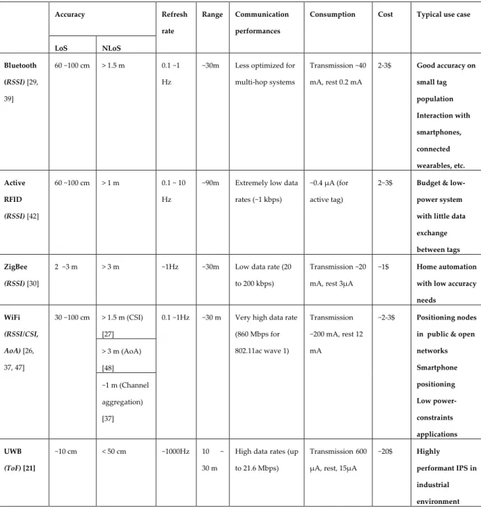
The performances and characteristics of each technology are summarized and compared in Table 1. It is difficult to compare benchmarks that have been evaluated in different environments, considering that indoor positioning is so dependent on the quality of the
Context
__________________________________________________________________________________
20
environment. As a consequence, this comparison aims rather to give an order of magnitude and a qualitative description of the performances obtained in the literature rather than precise benchmarks, which make little sense in this context.
Table 1. Comparison of the positioning performances of various radio technologies Accuracy Refresh
rate
Range Communication performances
Consumption Cost Typical use case
LoS NLoS Bluetooth (RSSI) [29, 39] 60 ~100 cm > 1.5 m 0.1 ~1 Hz
~30m Less optimized for multi-hop systems Transmission ~40 mA, rest 0.2 mA 2-3$ Good accuracy on small tag population Interaction with smartphones, connected wearables, etc. Active RFID (RSSI) [42] 60 ~100 cm > 1 m 0.1 ~ 10 Hz
~90m Extremely low data rates (~1 kbps)
~0.4 μA (for active tag)
2~3$ Budget & low-power system with little data exchange between tags ZigBee
(RSSI) [30]
2 ~3 m > 3 m ~1Hz ~30m Low data rate (20
to 200 kbps)
Transmission ~20 mA, rest 3μA
~1$ Home automation with low accuracy needs WiFi (RSSI/CSI, AoA) [26, 37, 47] 30 ~100 cm > 1.5 m (CSI) [27]
0.1 ~1Hz ~30 m Very high data rate (860 Mbps for 802.11ac wave 1) Transmission ~200 mA, rest 12 mA ~2-3$ Positioning nodes in public & open networks Smartphone positioning Low power-constraints applications > 3 m (AoA) [48] ~1 m (Channel aggregation) [37] UWB (ToF) [21] ~10 cm < 50 cm ~1000Hz 10 ~ 30 m
High data rates (up to 21.6 Mbps)
Transmission 600 μA, rest, 15μA
~20$ Highly
performant IPS in industrial environment
Context
__________________________________________________________________________________
21
II.1.4 Positioning algorithms
II.1.4.1 Definition
There are different approaches to compute a position from a set of distances to reference points. The most intuitive one is to approach this multilateration problem from a purely geometrical perspective. At least two anchors are needed in a 2D space, and at least three in a 3D one. For the sake of clarity, the following figures are always represented in 2D; however, the related discussion can be extended to a 3D problem without loss of generality.
An example of a configuration with two anchors is shown below in Fig. 2. Two anchors A1and A2 are estimating respectively the distances R1 and R2 to a tag T1. Geometrically, there
are two possible trilateration solutions, which are symmetric over the axis (A1, A2). If there
are not any other anchors available, the actual solution will often be extracted from the context. For example, the space below the axis (A1, A2) might not physically accessible, or the
tag could observe environmental information indicating its presence in the upper half. Nevertheless, it is usually recommended to have at least one additional anchor to identify the right solution out of the solution pairs. This same problem also applies in three-dimensions: if only three anchors are available, two solutions, symmetric over the plan formed by the three anchors, will be geometrically possible. Some extra context information will be needed to find out the real position.
Fig. 2. 2D trilateration with two anchors
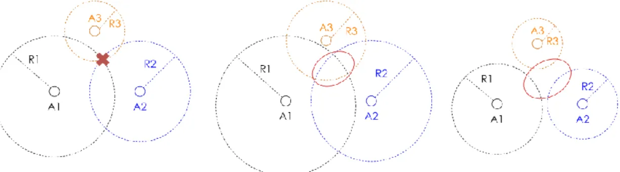
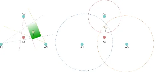
From Fig. 2 above, it seems that the geometrical problem that multilateration has to solve is quite straight-forward. However, we have been ignoring so far the distance measurement bias. In any real-world IPS, ranging are noisy and their accuracy will vary depending on the technology used and the complexity of the environment. As a consequence, the multilateration algorithm has to compensate the individual ranging bias. This problem can be represented by the area of intersection or disjunction of circles, as shown in Fig. 3. In this example, three anchors A1, A2, and A3 estimate their respective distances R1, R2, and R3 to a
mobile tag. The ideal geometrical case is shown on the left: the distances estimated are completely accurate and there is a single solution, which is the intersection of the circles of radius R1, R2, and R3. However, this is not true anymore as long as a bias is introduced on the
ranging outputs. If the anchors are overestimating the distance, as shown in Fig. 3. (middle), the intersection of the ranging circles forms a surface and not a single point. In the opposite
Context
__________________________________________________________________________________
22
case (right), if the distances are underestimated, the ranging circles are disjointed. The area of the tag’s potential position is circled in red. The surface of junction or disjunction will depend on the bias distribution. Considering this issue, the multilateration problem is less trivial than a simple geometrical resolution.
Fig. 3. Multilateration problem with different types of ranging bias: None (left), over-estimation (middle), under-estimation (right)
One parameter that is particularly relevant to solve this problem is the Ranging Deviation (RD). RD is the mean-squared error of a given position relative to the distances observed by the anchors, as detailed in the following definition.
Definition 1: For a set of anchors (A1,…, AN) measuring the distances (R1,…, RN) to a
mobile tag T, let P = (x,y,z) a candidate position for T. With (D1, …, DN) the real distances
from the anchors (A1,…, AN) to P, the ranging deviation RDi of an anchor Aiof a position P is
defined as:
𝑅𝐷
𝑖(𝑃) = (𝐷
𝑖− 𝑅
𝑖)²
The total ranging deviation (TRD) of P is defined as:
Eq. 1
𝑇𝑅𝐷(𝑃) = ∑(𝐷
𝑖− 𝑅
𝑖𝑁
𝑖=1
)²
RD is a good indicator on how coherent a given position is with the observed distances. A position with a low RD is more likely to be the real one. Also, for a given set of rangings, the minimum RD observed on the whole 2D or 3D space is a good indicator of the measurements noise. If even the minimum RD obtained is high, i.e., one cannot obtain a plausible solution, the distances obtained are not matching each other which means that the ranging measurements are being seriously degraded.
The last fundamental concept for multilateration algorithm is the idea of trajectory. The position is not only a spatial function but also a temporal one: two positions for the same
Context
__________________________________________________________________________________
23
node recorded at short intervals are obviously strongly correlated to each other, as there are physical limits to the speed that a node can reach. This aspect is more application-dependent. Some knowledge about the typical speed that a node can reach will tremendously help, as there may be a slight difference between an IPS monitoring a cow breeding farm [49] and a one monitoring a kart fleet [50]. Also, a real-time localization system (RTLS) will typically run continuously and record trajectories, where some IPS might be solicited only occasionally, for example, to find a tagged object in a warehouse. In that last case, nodes are typically still and there are huge time gaps between two localizations, which means that the trajectory cannot be exploited. As a consequence, when the application context allows it, a memory effect can be used for the positioning algorithm, where the position obtained at a given time by multilateration can be filtered based on the previous ones.
II.1.4.2 Multilateration algorithms
Considering all the aspects aforementioned, there are three main types of multilateration algorithms:
▪ Geometrical, where the solution is extracted from a set of trilateration similarly to the case illustrated in Fig. 2.
• Iterative, where a solution minimizing the ranging deviation is obtained heuristically by series of iterations in an optimal direction.
• Stochastic, where the surface covered by the IPS is modeled by a probability distribution of the tag’s potential presence. This probability distribution is usually obtained from the correlation between a position predictor and the ranging outputs. In the following, we give an overview of the major approaches of the state-of-the-art for these three types of approaches.
Geometrical: geometrical approaches are simply based on the trilateration process
illustrated in Fig. 2, where a set of 2 solutions can be obtained for each peer of anchors. In an ideal situation where the measurements are absolutely unbiased, a third anchor is enough to find out which of the two solutions is correct, and the distance information brought by any additional anchors will be completely redundant. In other words, if multiple anchors are available and there is no ranging bias, any triplet of anchors will give the same trilateration result. However, this does not hold true anymore if noise is introduced: the solutions obtained for each couple or triplet of anchors will slightly differ. When multiple anchors are available, there are two main ways to exploit the redundancy: either by using a selection process or by applying a centroid. In the first case, the closest anchors to the target, i.e., the ones that are the most likely to be accurate, are chosen and the other ones are ignored. This approach is used for example in the BAST algorithm [51]. In the second case, all the possible trilateration are computed and the final solution is computed as the centroid of all the trilateration solutions. This approach is used by Lazaro et al. in [52] for breast tumor detection with an UWB radar: a multi-static radar based on multiple UWB antennas is proposed, which estimates the reflection time to the tumor; as the propagation coefficient in
Context
__________________________________________________________________________________
24
the monitored human body varies from one antenna to another, introducing a unknown bias, a weighted centroid approach is proposed to estimate the tumor’s location.
Iterative: The goal behind iterative methods is to find a position minimizing the ranging
deviation with a minimum effort. Bruteforcing the RD optimization problem by computing the RD for every point of the monitored space for a given granularity has a huge computational cost. However, it can be approached with conventional heuristics for least-square optimization problems, notably gradient search and Gauss-Newton algorithm [53]. An intuition for these two approaches is the following: given an arbitrary starting point, they find the direction that optimizes the RD reduction problem, iterate in that direction, and repeat the process until a satisfying solution has been obtained or the maximum number of iterations has been reached. However, the choice of the optimal direction is defined differently for the two methods.
For gradient search, the direction chosen is the opposite direction to the gradient. The iterations are defined as following:
Definition 2: Let P0 an arbitrary starting position. With µ a positive coefficient, a single
iteration of gradient descent is defined by:
∀𝑛 ∈ 𝑁 , 𝑃
𝑛+1= 𝑃
𝑛− 𝜇∇𝑇𝑅𝐷(𝑃
𝑛)
The choice of µ is mostly a matter of compromise. If µ is too high, the gradient descent may tend to go always beyond the targeted minimum which would trigger a “zig-zag” effect. If µ is too low, the algorithm will tend to repeat several iterations in the same direction that could have been done in a single step. There two main things to retain regarding its accuracy and efficiency:
• it is based on the global ranging deviation and not the individual ranging deviation of each anchor
• it is an approximation of first-order
On the other hand, the direction is computed from the Jacobian for the Gauss-Newton method. In that approach, the iteration steps are defined as follows:
Definition 3: Let P0 an arbitrary starting position. A single iteration of the
Gauss-Newton algorithm is defined by:
∀𝑛 ∈ 𝑁 , 𝑃𝑛+1= 𝑃𝑛− (𝐽𝑅𝐷𝑛 𝑇 . 𝐽 𝑅𝐷𝑛) −1 . 𝐽𝑅𝐷𝑛 𝑇 . 𝑇𝑅𝐷(𝑃 𝑛)
Where JRDn is the Jacobian of the ranging deviation:
𝐽𝑅𝐷𝑛= ( 𝜕𝑅𝐷1(𝑃𝑛) 𝜕𝑥 ⋯ 𝜕𝑅𝐷1(𝑃𝑛) 𝜕𝑧 ⋮ ⋱ ⋮ 𝜕𝑅𝐷𝑁(𝑃𝑛) 𝜕𝑥 ⋯ 𝜕𝑅𝐷𝑁(𝑃𝑛) 𝜕𝑧 )
Context
__________________________________________________________________________________
25
Contrary to Gradient descent, Gauss-Newton is based on a second-order approximation. Because of that, it typically converges much faster than gradient descent, but convergence is not guaranteed [53]. Usually, for both gradient descent and Gauss-Newton, it is advisable to use a position extracted from the aforementioned geometrical methods rather than a random point. For an IPS that is running continuously, an alternative is to use the last recorded position as starting point, as the current position might me assumed to be very close from the previous one.
Stochastic: Contrary to the two previous categories, stochastic approaches are based on a
memory effect, which means they take into account not only the current ranging but also the previous positions recorded. The principle is based on visualizing the whole map as a probability distribution of a given tag presence at a given time. Indeed, a given position might be coherent from a ranging perspective (i.e., has a low TRD) but incoherent from a trajectory perspective (i.e., implies an unrealistic speed or acceleration). Stochastic methods aggregate these two aspects by defining the presence probability distribution as a combination of these two factors. Probabilistic positioning methods in the state-of-the-art are mostly variations of particle filters [54, 55].
In the context of localization, the goal of particle filters is to find the position a node by correlating the knowledge that the IPS has of the environment to the current and past observations of the nodes within that environment. A good example is the case of an airplane flying over an environment: the airplane needs to locate itself on a map; the only parameter that it can sense is its altitude, but the relief on the whole map is known. The plane is going in a straight direction at a steady speed. With a single measurement, there are probably multiple points on the map that match its observed height. However, once the altitude measurements start being accumulated, they will form a pattern that can only possibly match a single portion of the map, allowing the airplane to locate itself.
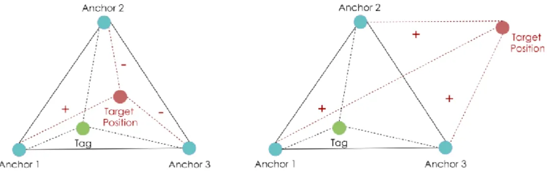
In the case of the discussed IPS, the environment data that are known are the anchors' position, and the parameter observed is the tag-anchor distance. The principle of a particle filter applied to a time-of-flight positioning problem is illustrated below in Fig. 4. The particle filter starts by generating a fleet of N particles with random positions across the map
(Fig. 4., left). Then, it associates likeliness to each of these points, based on their TRD with the
current ranging outputs of the anchors: particles with a low TRD have a high likeliness, and vice-versa. The particles are then resampled: particles with high likeliness are duplicated, and particles with low likeliness are eliminated (middle). Finally, each particle is moved by a vector randomly sampled from the space of realistic displacements (right). This space is determined from the context information, e.g., maximum realistic speed or acceleration. The likeliness is typically estimated from an Extended Kalman Filter [56].