UNIVERSITÉ DE MONTRÉ AL
TUNABLE FERRITE PHASE SHIFTERS USING SUBSTRATE
INTEGRATED WAVEGUIDE TECHNIQUE
YONG JU BAN
DÉ PARTEMENT DE GÉ NIE É LECTRIQUE É COLE POLYTECHNIQUE DE MONTRÉ AL
MÉ MOIRE PRÉ SENTÉ EN VUE DE L‟OBTENTION DU DIPLÔ ME DE MAÎTRISE È S SCIENCES APPLIQUÉ ES
(GÉ NIE É LECTRIQUE) DÉ CEMBRE 2010
UNIVERSITÉ DE MONTRÉ AL
É COLE POLYTECHNIQUE DE MONTRÉ AL
Ce mémoire intitulé:
TUNABLE FERRITE PHASE SHIFTERS USING SUBSTRATE
INTEGRATED WAVEGUIDE TECHNIQUE
présenté par : BAN, YONG JU
en vue de l‟obtention du diplôme de : Maîtrise ès sciences appliquées a été dûment accepté par le jury d‟examen constitué de :
M. CARDINAL, Christian, Ph. D., président
M. WU, Ke, Ph. D., membre et directeur de recherche M. DESLANDES,Dominic, Ph. D., membre
DEDICATION
To my lovely wife Jeong Min And my two sons Jione & Junone
ACKNOWLEDGEMENTS
I would like to express my sincere gratitude to my supervisor, Prof. Ke Wu, for having accepted me and given me the opportunity to pursue my master study in such a challenging and exciting research field, and for his invaluable guidance and encouragement throughout the work involved in this thesis.
I would like to thank Mr. Jules Gauthier, Mr. Jean-Sebastien Décarie and other staffs of Poly-Grames Research Center for their skillful technical supports during my study and experiments. I thank Zhenyu Zhang, Fanfan He and Anthony Ghiotto for their helpful discussions. And many thanks should be extended to Sulav Adhikari for his invaluable supports for my study and thesis.
I also appreciate my colleagues Xiaoma Jiang, Nikolay Volobouev, Adrey Taikov, Marie Chantal, Parmeet Chawala, Jawad Abdulnour and Shyam Gupta in SDP for their understanding and endurance for my study.
Finally my special thanks go to my wife Jeong-Min, my two sons Jione and Junone for their endless love and endurance that encouraged me to the success.
RÉ SUMÉ
Le guide d'ondes intégré au substrat (SIW) est une technique très prometteuse du fait qu‟il permet d‟utiliser des avantages des guides d'ondes et des lignes de transmission
planaires. Comme guide d'ondes, nous pouvons obtenir des avantages tels que de faible pertes, un facteur de qualité élevé, les possibilités de grande puissance et de petit rayonnement. Et comme la ligne de transmission planaire, nous pouvons en faire la fabrication avec une taille compacte et à un faible coût.
Dans ce memoire, des déphaseurs à ferrite sont conçus et expérimentés en utilisant la technique du guide d'ondes intégrée au substrat (SIW) pour profiter des avantages mentionnés ci-dessus. La première tentative de concevoir un déphaseur à ferrite utilisant le SIW a été faite par Wenquan et autres.
Cependant, un résultat expérimental n'a pas été présenté peut-être en raison d'une difficulté de fabrication d‟un toroïde de ferrite qui était censé être utilisé dans la
conception. Une bonne performance de circulateur de ferrite en structure SIW a été obtenue par William et autres. Cependant, la conception a été implantée dans une polarisation fixe.
Dans cette lettre, des déphaseurs réglables à ferrite utilisant la technique SIW sont présentés et expérimentalement démontrés. Des tores de ferrite sont placés où la polarisation circulaire se produit le long du SIW. La polarisation du champ magnétique statique est appliquée pour magnétiser les tores de ferrite dans la direction transversale.
Dans ce memoire, la méthode de polarisation du champ magnétique variable est présentée et mise en application. Des résultats de mesure et de simulation de phase d‟un simple toroïde de ferrite ainsi que celui d‟un double toroïde de ferrite seront présentés
Les résultats de mesures des déphaseurs variables à simple et double toroïde de ferrite utilisant la technique SIW ont été présentés. Environ 160° de déphasage a été réalisé avec un déphaseur à simple toroïde de ferrite et 190° de déphasage a été réalisé avec un déphaseur à double toroïde de ferrite. La figure de mérite à 24 GHz avec un déphaseur a double toroïde de ferrite utilisant la technique SIW réalisée dans cette expérience est de 95°/dB.
ABSTRACT
Substrate Integrated Waveguide (SIW) is a very promising technique in that we can make use of the advantages of both waveguides and planar transmission lines. As a waveguide, we can get such advantages as low loss, high Q factor, high power capability and small radiation. And as a planar transmission line, we can fabricate it in a compact size at a low cost. In this letter, ferrite phase shifters are designed and experimented using substrate integrated waveguide (SIW) technique to take advantages mentioned above. The first attempt to design a ferrite phase shifter using SIW was made by Wenquan et al. However, an experimental result was not presented maybe because of a fabrication difficulty of ferrite toroid which was supposed to be used in the design. A quite good performance of ferrite circulator in SIW structure was obtained by William et al. However, the design was implemented in a fixed bias. In this letter, tunable ferrite phase shifters using SIW technique are presented and experimentally demonstrated. Ferrite slabs are placed where circular polarization occurs along the SIW. Static magnetic field bias is applied to magnetize the ferrite slabs in transverse direction. In this letter, a variable magnetic field biasing method is presented and implemented. Measurement and simulation results of both single ferrite slab and double ferrite slabs phase are presented.
Measurement results of a tunable single and double ferrite slab phase shifters using SIW technique were presented. About 160° of differential phase shift was achieved in the single slab ferrite phase shifter and 190° of differential phase shift was achieved in
the double ferrite slab phase shifter. The achieved figure of merit at 24GHz with the double ferrite slab phase shifter using SIW technique in this experiment is 95°/dB.
CONDENSÉ EN FRANÇ AIS
1. Introduction
Le guide d'ondes intégré au substrat (SIW) est une technique très prometteuse du fait qu‟il permet d‟utiliser des avantages des guides d'ondes et des lignes de transmission
planaires. Comme guide d'ondes, nous pouvons obtenir des avantages tels que de faible pertes, un facteur de qualité élevé, les possibilités de grande puissance et de petit rayonnement. Et comme la ligne de transmission planaire, nous pouvons en faire la fabrication avec une taille compacte et à un faible coût.
Dans ce memoire, des déphaseurs à ferrite sont conçus et expérimentés en utilisant la technique du guide d'ondes intégrée au substrat (SIW) pour profiter des avantages mentionnés ci-dessus. La première tentative de concevoir un déphaseur à ferrite utilisant le SIW a été faite par Wenquan et autres.
Cependant, un résultat expérimental n'a pas été présenté peut-être en raison d'une difficulté de fabrication d‟un toroïde de ferrite qui était censé être utilisé dans la
conception. Une bonne performance de circulateur de ferrite en structure SIW a été obtenue par William et autres. Cependant, la conception a été implantée dans une polarisation fixe.
Dans cette lettre, des déphaseurs réglables à ferrite utilisant la technique SIW sont présentés et expérimentalement démontrés. Des tores de ferrite sont placés où la polarisation circulaire se produit le long du SIW. La polarisation du champ magnétique statique est appliquée pour magnétiser les tores de ferrite dans la direction transversale.
Dans ce memoire, la méthode de polarisation du champ magnétique variable est présentée et mise en application. Des résultats de mesure et de simulation de phase d‟un simple toroïde de ferrite ainsi que celui d‟un double toroïde de ferrite seront présentés
II. CONSIDÉ RATIONS THÉ ORIQUES ET TOPOLOGIQUES
A. Déphaseur à simple toroïde de ferrite
Un guide d'ondes rectangulaire est synthétisé dans un substrat diélectrique au moyen de deux lignes de via métalliques. Une fente ouverte est usinée dans le SIW de sorte qu‟un tore de ferrite soit inséré à la fente ouverte usinée. Puis, chaque ouverture du haut
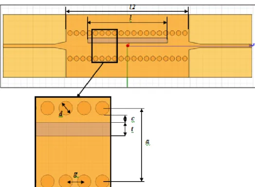
et du bas du mur du SIW est couverte en utilisant une couche mince de cuivre. Afin d'éviter une fuite de micro-onde, les feuilles de cuivre minces sont entièrement soudées au revêtement de cuivre du SIW. La figure 1 montre la géométrie du déphaseur à simple toroïde de ferrite implanté en SIW. Pour les mesures, une transition de SIW au microruban est adoptée. Les détails des paramètres de dimensions utilisés dans la figure 1 sont énumérés dans le tableau 1. Le SIW est fabriqué sur un substrat de RT/duroid 6010.
Fig. 1. La géométrie du déphaseur a simple toroïde de ferrite utilisant la technique SIW
Largeur du SIW a 4.064mm
Diamètre des Via d 0.77mm
Distance entre les Via g 1.016mm Distance de la ferrite au mur c 0.4mm
La longueur du ferrite l 12.7mm La largeur du ferrite t 0.762mm La hauteur du ferrite h 0.762mm
La longueur du SIW l2 20mm
La hauteur du substrat b 0.635mm
Table 1. Les paramètres dimensionnels utilisés dans la figure 1
Il y a des régions naturelles de polarisation circulaire dans des guides d'ondes rectangulaires qui fonctionnent en mode TE10. Quand des tores de ferrite sont placés dans ces régions, des ondes de polarisation circulaire sont excitées dans la ferrite parce
que l'onde circulairement polarisée tournant dans la même direction que le dipôle magnétique de précession a une forte interaction avec la ferrite. Le sens de la polarisation (gauche ou droite) dépend de la direction de propagation des ondes dans le guide d'ondes. Les ondes voyageant dans la direction directe dans un guide d'ondes excitent dans la ferrite les ondes de polarisation circulaire avec un sens de polarisation, et les ondes voyageant dans la direction opposée excitent dans la ferrite les ondes de polarisation inverse.
Comme la constante de propagation de l‟onde voyageant dans une direction devient différente de celle de l‟onde voyageant dans la direction opposée provoquée par une
polarisation circulaire différente, il y a des différences de phases liées à la transmission des deux types d‟ondes dans le guide d'ondes à ferrite. Quand un tore de ferrite est
chargé dans un guide d'ondes, une équation transcendantale pour la constante de propagation β est donnée par
Afin de magnétiser un simple toroïde de ferrite dans un déphaseur SIW, un système de noyau d'électro-aimant est utilisé. Le déphaseur à simple toroïde de ferrite est placé entre deux noyaux d'électro-aimant. Le SIW est fabriqué sur un substrat de RT/duroid 6010 d‟épaisseur de 0.762 millimètres et de constante diélectrique de 10.2. Et un tore de
ferrite est usiné en TCI NF-5000 qui est une ferrite de nickel. Il a 5000G de saturation magnétique, 100 de “linewidth” et une constante diélectrique de 13
B. Déphaseur a double toroïde de ferrite
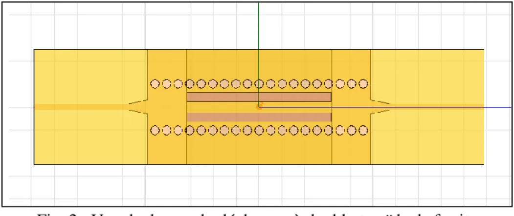
Dans la fabrication d'un déphaseur à double toroïde, la seule différence avec celui à simple toroïde est qu'une fente additionnelle est usinée dans le SIW de sorte que deux tores de ferrite puissent être insérés dans le SIW avec une symétrie dimensionnelle entre eux.
Fig. 2. Vue de dessus du déphaseur à double toroïde de ferrite
L'analyse du déphaseur à double toroïde de ferrite est très semblable à celle de la géométrie à simple toroïde parce que les tores de ferrite des côtés opposés du guide d'ondes sont magnétisés dans la direction opposée, les deux tores de ferrite présentent la même perméabilité à l‟onde dans le guide d'ondes et le champ est symétrique. Une
équation transcendantale de la constante de propagation, β est donnée par
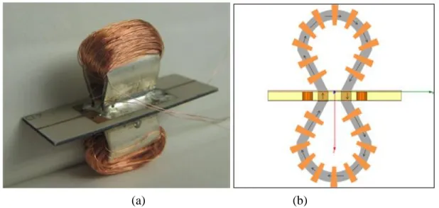
Pour la magnétisation du déphaseur à ferrite, un système de boucle fermé de champ magnétique est conçu comme montré dans la figure 3 (b). Pour les ouvertures de dessus et de bas du SIW, deux longs plats en acier sont préparés et fabriqués en forme d'Omega. La distance entre les deux extrémités du plat en forme d'Omega a été ajustée pour être identique à celle entre les deux tores de ferrite. Et chaque plat en acier est préparé avec un plaquage en argent de sorte qu'il puisse permettre la soudure. Avant que le plat en forme d'Omega soit soudé à chaque ouverture du SIW, une bobine est enroulée autour du plat de sorte qu'une magnétisation des deux tores de ferrite puisse être réalisée par le courant continu appliqué aux bobines enroulées autour des plats d'Omega.
(a) (b)
Fig. 3. (a) Un déphaseur à double toroïde complet utilisant la technique SIW (b) Une vue en coupe transversale illustrant une boucle fermée de champ magnétique statique
La figure 3 (a) montre un déphaseur à double toroïde complet utilisant la technique SIW technique. Un fil très mince, qui a 0.07mm de diamètre, est enroulé autour de chaque plat en forme d'Omega avec 750 tours.
III. RESULTATS DE SIMULATIONS ET DE MESURES A. Déphaseur à simple toroïde de ferrite
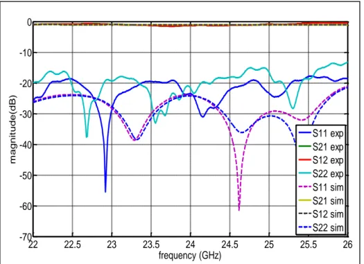
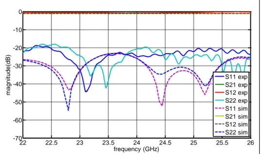
La figure 3 montre les résultats de mesures et de simulations des pertes de retour d‟un déphaseur à simple toroïde de ferrite sans un champ magnétique externe. On
constate que plus de 20 dB de pertes de retour peuvent être obtenues en simulation et 15 dB en mesure. La différence entre les résultats de simulation et de mesure peut venir d'une petite ouverture d‟air entre les tores de ferrite et la fente ouverte dans le SIW ainsi que d‟une armature imparfaite des larges murs faits des bandes de feuilles de cuivre. On constate également que les pertes d‟insertion simulées et mesurées sont plus petites que
1.5dB.
Fig. 4. Les résultats de mesure et simulations d‟un depraver SIW à simple toroïde de ferrite sans champs magnétique externe
22 22.5 23 23.5 24 24.5 25 25.5 26 -70 -60 -50 -40 -30 -20 -10 0 frequency (GHz) m agn it ude (dB) S11 exp S21 exp S12 exp S22 exp S11 sim S21 sim S12 sim S22 sim
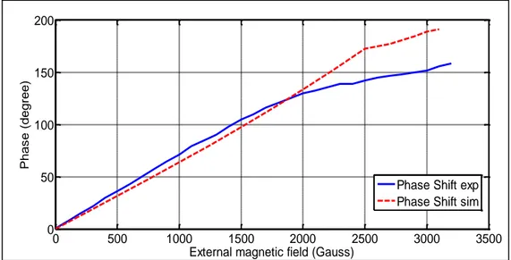
A partir de la variation de phase entre S21 et S12 par le changement de l'intensité du champ magnétique externe, il est possible de calculer le déphasage résultant du déphaseur à simple toroïde conçu. La figure 5 montre les résultats du déphasage simulé et mesuré. Environ 190° de déphasage a été réalisé en simulation avec 3200G de l'intensité du champ magnétique externe et environ 160° de déphasage est obtenu expérimentalement avec la même intensité du champ. Plus de déphasage pourrait être obtenu si plus d'intensité du champ magnétique externe était appliquée au déphaseur conçu. En regardant la courbe du facteur de démagnétisation, seulement la moitié de la magnétisation a été réalisée dans cette expérience.
Fig. 5. Résultats de mesure et de simulation du déphasage différentiel à 24GHz
B. Déphaseur à double toroïde de ferrite
Les résultats de simulations et de test des paramètres S du déphaseur à double toroïde de ferrite sont compares dans la figure 6. . Les pertes de retour dans la bande de
0 500 1000 1500 2000 2500 3000 3500 0 50 100 150 200
External magnetic field (Gauss)
Pha s e (de gre e)
Phase Shift exp Phase Shift sim
fréquences d‟intérêt de 22GHz à 26GHz, sont meilleures que 20 dB dans les
simulations et 18 dB dans les mesures.
Fig. 6. Résultats de simulation et de mesure du déphaseur à simple toroïde de ferrite sans polarisation du champ magnétique externe
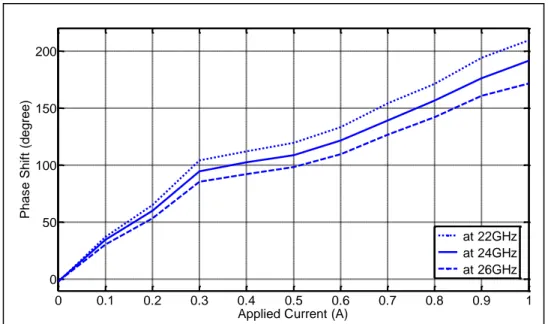
La figure 7 montre le déphasage mesuré du déphaseur à double toroïde. La variation de phase est mesurée en changeant le courant appliqué à la bobine. On peut noter que le déphaseur montre une augmentation linéaire de déphasage en fonction du courant appliqué. Ç a signifie que le déphaseur est opéré en-dessous de la saturation magnétique car la perméabilité a une diminution linéaire jusqu'à la saturation magnétique.
22 22.5 23 23.5 24 24.5 25 25.5 26 -70 -60 -50 -40 -30 -20 -10 0 frequency (GHz) m agn it ude (dB) S11 exp S21 exp S12 exp S22 exp S11 sim S21 sim S12 sim S22 sim
Fig. 7. Résultats de mesures et simulations du déphaseur SIW à simple toroïde de ferrite
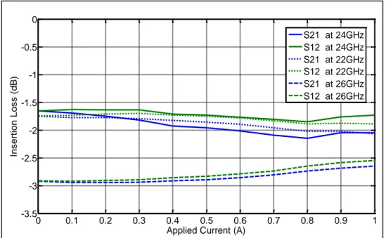
Afin de calculer la “Figure de Mérite” du déphaseur à double toroïde de ferrite, les pertes d‟insertion ont été capturées par le changement du courant appliqué comme montré dans la figure 8. On observe que les pertes d‟insertion de l‟onde se propageant dans la direction directe sont déviées de celle de l‟onde se propageant dans la direction opposée quand le courant appliqué augmente. Dans cette expérience, la figure de mérite réalisée à 24GHz avec le déphaseur à double toroïde de ferrite utilisant la technique de SIW est de 95°/dB. 0 0.1 0.2 0.3 0.4 0.5 0.6 0.7 0.8 0.9 1 0 50 100 150 200
Applied Current (A)
Pha s e Shif t (de gre e) at 22GHz at 24GHz at 26GHz
Fig. 8. Les pertes d‟insertion mesurées du déphaseur à double toroïde de ferrite
IV. CONCLUSION
Les résultats de mesures des déphaseurs variables à simple et double toroïde de ferrite utilisant la technique SIW ont été présentés. Environ 160° de déphasage a été réalisé avec un déphaseur à simple toroïde de ferrite et 190° de déphasage a été réalisé avec un déphaseur à double toroïde de ferrite. La figure de mérite à 24 GHz avec un déphaseur a double toroïde de ferrite utilisant la technique SIW réalisée dans cette expérience est de 95°/dB. 0 0.1 0.2 0.3 0.4 0.5 0.6 0.7 0.8 0.9 1 -3.5 -3 -2.5 -2 -1.5 -1 -0.5 0
Applied Current (A)
Ins ert ion Los s (dB) S21 at 24GHz S12 at 24GHz S21 at 22GHz S12 at 22GHz S21 at 26GHz S12 at 26GHz
TABLE OF CONTENTS
DEDICATION………..iv AKNOWLEDGEMENTS………...v RÉSUMÉ……….…….vi ABSTRACT………....…………...viii CONDENSÉ EN FRANÇAIS………..……….x TABLE OF CONTENTS………..…xxii TABLE OF FIGURES………...….……...xxv TABLE OF TABLES………...xxx CHAPTER 1. INTRODUCTION………..1CHAPTER 2. MICROWAVE FERRITE THEORY………6
2.1. Ferrimagnetism ………6
2.2. Magnetization………8
2.3. Tensor Permeability ………9
2.4. Propagation in Longitudinal Magnetization………13
2.5. Propagation in Transverse Magnetization………21
2.6. Conclusion………...………25
CHAPTER 3.SUBSTRATE INTIGRATE WAVEGUIDE………27
3.1. Introduction ………27
3.3. Wave Propagation in Waveguide ……….….30
3.4. Substrate Integrated Waveguide……….….31
3.5. Substrate Integrated Waveguide……….….33
3.6. Transition of Microstrip to SIW ……….….36
3.7. Conclusion……… ……….….41
CHAPTER 4. SINGLE FERRITE SLAB PHASE SHIFTER USING SIW TECHNIQUE ………..42
4.1. Introduction and Modeling ………..42
4.2. Fabrication and Magnetization ………...49
4.3. Simulated and Measured Results..………...52
4.4. Conclusion………....………...58
CHAPTER 5. DOUBLE FERRITE SLAB PHASE SHIFTER USING SIW TECHNIQUE ………59
5.1. Introduction and Modeling ………..59
5.2. Fabrication and Magnetization ………....64
5.3. Measured Results ………....69
5.4. Conclusion ………....73
CONCLUSIONS and FUTURE WORKS ………75
Thesis Summary ………75
Future Work ………78
TABLE OF FIGURES
Fig.2.1. Normalized effective permeability with change of magnetic field at 25GHz for the ferrite which has 5000G saturation magnetization ………..16
Fig.2.2. Normalized imaginary part of positive permeability with change of magnetic field at 25GHz for NF-5000, LF-4800 and YG-1780 ………...19
Fig.2.3. Normalised effective permeability with change of magnetic field at 25GHz for NF-5000, LF-4800 and YG-1780 ………20
Fig.2.4 Normalised effective permeability of transverse magnetized NF-5000 with change of magnetic field at 25G ………..23
Fig.2.5 Comparison of normalized effective permeability of transverse magnetized ferrites with change of magnetic field at 25GHz ………...24
Fig.2.6 Normalised effective permeability of transverse magnetized ferrites with change of magnetic field at 25GHz ………...…25
Fig.3.1 Geometry of a Rectangular Waveguide ………...29 Fig.3.2 Various modes in rectangular waveguide ………..29 Fig.3.3 Configuration of the SIW synthesized by metallic via-hole arrays ………..33 Fig.3.4 Simulation result of the K band SIW ………..36 Fig.3.5 Transition model of Microstrip to SIW ………..38 Fig.3.6 Simulated result of the optimized transition model ………..39 Fig.3.7 IW with back to back connection ………..40 Fig.3.8 TRL calibration kit ………..40
Fig.3.9 Measured and simulated result of Return Loss and Insertion Loss of SIW back-to-back transition ………..41
Fig.4.1 Magnetic field propagation and the circular polarization at one forth location
in Substrate Integrated Waveguide ……….….43
Fig.4.2 Geometry of a rectangular waveguide loaded with a transversely biased
ferrite slab ………44
Fig.4.3 (a) The magnetic field in forward travelling wave shows a strong excitation in the ferrite which is transversely magnetized to the z direction. (b) The magnetic field in reverse travelling wave shows a weak excitation in the ferrite which is transversely
magnetized to the z direction ………47
Fig.4.4 Single slab ferrite phase shifter using Substrate Integrated Waveguide ……48
Fig.4.5 Single Fabricated SIW and ferrite ………50
Fig.4.6 Experiment setup for characterization of the ferrite phase shifter …………51 Fig.4.7 Ferrite phase sifter located in a electromagnet system ………52 Fig.4.8 Measured and simulated results of SIW single slab ferrite phase shifter without external magnetic field application ………53
Fig.4.9 Measured and simulated results of SIW single slab ferrite phase shifter with fully magnetized ferrite slab ………54
Fig.4.10 Measured and simulated results of phase split between S21 and S12 at 24GHz ………56
Fig. 4.11 Measured and simulated results of differential phase shift at 24GHz ……57 Fig. 4.12 Measured and simulated results of insertion loss at 24GHz ………58
Fig. 5.1 Geometry of a rectangular waveguide loaded with two symmetrical ferrite slabs ………59
Fig. 5.2 Geometry of double ferrite slabs phase shifter using SIW technique …… 60 Fig. 5.3 Simulated results of double ferrite slabs phase shifter using SIW technique in both without external magnetic bias and with external magnetic bias to full saturation magnetization ……… 61
Fig. 5.4 Simulated results of phase split between S21 phase and S12 phase ………62 Fig. 5.5 simulated results of differential phase shift ………63 Fig. 5.6 simulated results of insertion loss at 22GHz, 24GHz and 26GHz …………64 Fig. 5.7 Ferrite phase shifter with magnetic biasing system ………… ………66 Fig. 5.8 Ferrite phase shifter with double magnetic biasing system ………67 Fig. 5.9 Experimental setup of the double ferrite slabs phase shifter … ………68 Fig. 5.10 Measured and simulated results of SIW single slab ferrite phase shifter without external magnetic field bias ………69
Fig. 5.11 Measured phase split results of double ferrite slabs phase shifter ………70 Fig. 5.12 Measured phase shift of double ferrite slabs phase shifter ………71 Fig. 5.13 Measured Insertion Loss of double ferrite slabs phase shifter ………73
TABLE OF TABLES
Table 2.1 Material Data for NF-5000 ………..17 Table 2.2 Material Data for LF-4800………..17 Table 2.3 Material Data for YG-1780 ………..18 Table 3.1 Comparison of Characteristic for the several transmission lines…………32 Table 3.2 Parameters for Substrate Integrated Waveguide used in Fig 3.3 ……….35 Table 3.3 Calculated parameters for Microstrip impedance transition ……….37
CHAPTER 1
INTRODUCTION
Substrate Integrated Waveguide (SIW) is a very promising technique with which we can take the advantages of both waveguides and planar transmission lines. With this scheme, we can envision such advantages as low loss, high Q factor, high power capability, and small radiation or leakage. And also as a planar transmission line, we can fabricate it with compact size at low cost. Therefore, a large number of vigorous research activities have been seen on SIW technique and various microwave components and devices have been designed successfully using SIW technique. However, there were only few works reported in designing microwave ferrite devices based on SIW technique because there are difficulties in grafting conventional microwave ferrite devices onto SIW structure, which can be described as follows.
a. How to shape and integrate microwave ferrite materials into SIW as ferrites are hard-to-process ceramic materials.
b. How to make a good matching between microwave ferrite materials and laminate materials of SIW.
c. How to design an efficient magnetic field bias system to magnetize the ferrite materials in SIW.
In this thesis, tunable ferrite phase shifters are studied, modeled and experimentally demonstrated using Substrate Integrated Waveguide technique with the consideration of the above-mentioned difficulties.
Microwave ferrite phase shifters are widely used especially for military applications in phased array antenna systems for electrical beam steering by providing different phase states to the radiating elements. The use of nonreciprocal phase shifters in phased array antenna systems is widespread. Ince and Temme, describing both ferrite and diode phase shifters, have studied various antenna feeds and the application of phase shifters [1].
Normally, a typical phased array antenna system consists of a good number of radiating elements, the same quantity of phase shifters are also required. As conventional ferrite phase shifters are made of conventional rectangular waveguide, the manufacturing cost is much higher than its competitive phase shifters and the dimension-related volume is also much larger and heavier. Thus, these drawbacks prevent ferrite phase shifters from being used in commercial applications in spite of their many advantages. Therefore, the development of ferrite phase shifters using planar printed circuit board provides a desirable alternative to the conventional rectangular waveguide ferrite phase shifters.
If a slab of ferrite in waveguide is placed at the position of circular polarization and magnetized perpendicular to the plane of the circular polarization, the effective permeability of the ferrite can be changed by varying the strength of the biasing magnetic field and result in phase shifting of the waveguide. Moreover, since the hand of rotation of the circular polarization is opposite on the opposite side of the waveguide, two ferrite slabs magnetized in opposite directions on opposite sides of the waveguide can yield the most efficient phase shifting [2].
There have been several reported works on the design of ferrite phase shifters based on planar structures. Most of such attempts were implemented utilizing microstrip meander structures. Regarding the research work with the SIW technique, the first attempt to integrate a ferrite toroid into a SIW in order to make a ferrite phase shifter was made by Wenquan Che et al [3]. However, there was no experimental result provided in the paper. Probably it was too difficult to insert a toroidal ferrite core into the SIW as the structure required a quite small size of ferrite toroid.
There was another attempt to design a ferrite phase shifter using the SIW technique and ferrite LTCC materials [4].However, the measured “figure of merit” in that paper was quite low as compared with other conventional ferrite phase shifters implemented in rectangular waveguides.
There was also a further attempt to integrate a ferrite disk into an SIW circulator was made by William D‟Orazio and Ke Wu [5].It presented a very successful example of circulator design with a simple and clear method of ferrite integration into SIW. However, the magnetic field bias system was not integrated in the design.
The motivation of this thesis work is to study and demonstrate a possibility of designing ferrite phase shifters using SIW technique so that a ferrite phase shifter is fabricated in planar form and manufactured at low cost. If an SIW ferrite phase shifter can be manufactured at low cost with an equivalent “figure of merit” to a conventional rectangular waveguide ferrite phase shifter, the ferrite phase shifter can be very useful for various commercial applications.
This thesis is organized in 5 chapters.
In Chapter 2, basic ferrite theory is reviewed and verified. And it is presented that how the ferrite is chosen and how the ferrite behaves at K band, especially at 25GHz. The definition of Ferrimagnetism is discussed and magnetization equation is introduced. Then, tensor permeability is derived and ferromagnetic resonance is explained. More importantly, based on the basic ferrite theory, it is also described how ferrite materials react when the ferrite is longitudinally magnetized and transversely magnetized, respectively.
In Chapter 3, Substrate Integrate Waveguide (SIW) is presented. First of all, waveguide theory is provided in a brief term and applied to substrate integrated waveguide. Then, design rules of SIW are discussed. A simple SIW is modeled and simulated for K band. Then, a transition from microstrip to SIW is studied and designed. In Chapter 4, a single ferrite slab phase shifter using SIW technique is designed, fabricated and measured. It is presented that how a ferrite slab is integrated into a simply machined slot in SIW and how an SIW ferrite phase shifter can easily be made. Also, characteristics of finite ferrite materials in practical applications are discussed and applied in the model. To verify the design, nonreciprocal circular polarizations of the single ferrite slab are visualized in 3D model based on HFSS. And then, experimental results are compared with simulation results.
In Chapter 5, a double ferrite slab phase shifter is designed, fabricated and then, measurement results are presented. As a practical design solution of planar ferrite phase shifters, the ferrite phase shifter is devised in a very simple form to be prototyped at low
cost as compared with not only rectangular waveguide devices but also other planar type of ferrite phase shifters. And some design ideas are developed for the ferrite phase shifter in order to reduce the shape demagnetization factor of ferrite slabs such that a more phase shifting can be achieved with lower external magnetic field. At the end of this chapter, the resulting “Figure of Merit” is presented.
CHAPTER 2
MICROWAVE FERRITE THEORY
2.1 Ferrimagnetism
Magnetism is an important part of electrical and electronic circuits and systems. Iron and its alloys are the most abundantly used magnetic materials. However, eddy currents limit the usefulness of iron alloys at high frequencies, whereas ferrites are insulators that are able to provide magnetic cores for high frequency circuits. As magnetic ferrite materials are used in this thesis work, it is necessary to understand the theory behind the magnetic properties of ferrite materials.
Normally microwave ferrite materials can be sorted into three groups, namely spinels, garnets, and hexagonal ferrites.
The ferrimagnetic properties of the spinels (MOFe2O3) result from the orientation of
the net magnetic moments of the metallic ions. The magnetic moments of the ions at the tetrahedral sites cancel the moments of 8 of the ions at octahedral sites. The remaining 8 octahedral ions give the ferrite a net magnetic moment.
Garnets (3M2O35Fe2O3) have crystal structures that are different from those of the
spinels in two respects. First, in the garnet structure there are three types of sites for metallic ions, instead of the two site types in the spinel structure. Second, all the sites in the garnet structure are filled.
Hexagonal ferrites (MO6Fe2O3) have hexagonal crystal structures that make strong
magnetic anisotropic energy. The M in the hexagonal ferrites represents Barium, Strontium or some others.
There are two kinds of magnetic moments existing in ferrite materials. The magnetic moment of an ion is the sum of two different moments: one due to the electron spin, and the other due to the orbital motion of the electrons. The magnetic moments of the ions can be calculated from the quantum numbers. Atoms that have only filled shells have no net magnetic moment, because the electron spins and the electron orbital effects cancel each other. The net magnetic moment due to electron spins depends on the number of spins in each direction. If all the spins are up, the moment is equal to the sum of the moments due to each spin. If all the spins are down, the net moment would be determined in the same manner. If some of the spins are up and others down, the difference in the number of spins in each direction would determine the net magnetic moment. [6]
Ferrimagnetism is a hybrid between ferromagnetism and antiferromagnetism as there is an incomplete cancellation of the atomic magnetic moments. Ferromagnetism is the spontaneous alignment of all the atomic magnetic moments, while antiferromagnetism is the complete cancellation of all the magnetic moment in the solid.
One important property of ferrites is that they have very low electric conductivity. For microwave application, the molecules of ferrites are engineered such that ferrites have less mechanisms of conduction.
2.2 Magnetization
The electron behaves as if it were a negatively charged sphere which is spinning about its own axis with a fixed angular momentum. The rotation of charge gives the electron a magnetic moment which is a function of its charge, angular velocity and size. Because of its angular momentum, the electron behaves as if it were a spinning magnetic top whose magnetic moment lies along its axis of rotation. It behaves like a gyroscope, but, instead of moving under the influence of gravitation, it moves due to the influence of magnetic forces which are those of any internal or applied magnetic field. [7]
A magnetic moment in ferrite material may be considered to be a magnetic top, spinning so that the magnetic moment and the angular momentum are parallel vectors. The ratio between the magnetic moment and the angular momentum is a constant for any material and is called the “gyromagnetic ratio” . It is given by
where and are the magnetic moment and the angular momentum vectors, respectively. Then, the gyromagnetic ratio is given as
where is the Lande spectroscopic splitting factor which is normally close to 2, and is the charge and is mass of the electron. We can calculate the gyroscope ratio as
.
In normal case, each magnetic moment is orientated so that there is no torque on it. However, if it is disturbed, the moment will precess as a gyroscope and the torque will be given by the following gyroscope equation [8].
As a disturbing magnetic field influences a magnetic moment, the disturbing torque on the moment is the cross-product of the magnetic field and the magnetic moment.
As the individual magnetic moments are all aligned within a domain, it can be assumed that the magnetic moment is proportional to the magnetization of ferrite material, . Therefore it gives the magnetisation equation as (2.4).
(2.4) is the classical equation of motion of magnetization which is useful because it gives simple mathematical results which are adequate for analysing many low-loss microwave ferrite applications [9].
2.3 Tensor Permeability
When the ferrite material is magnetized to saturation by a static magnetic field, in
the z-direction, the magnetic permeability of the ferrite due to an a.c magnetic field becomes anisotropic with rotational symmetry about the direction of the d.c magnetizing field. If the material is magnetized to saturation, it is assumed that all the individual
(2.2)
(2.3)
magnetic moments are aligned within the material. Let there also be a time-varying magnetic field, of time dependence, , that is small compared with the saturation
magnetic field. [10]
Then the total direction fields in the material will be Magnetic field intensity:
which gives rise to
Internal magnetization:
If substitution of these field values is made into (2.4) and the second order small term is neglected, we obtain
Taking the separate components of the field in the rectangular co-ordinate system, (2.5) becomes,
The first two equations of 2.6 are simultaneous equations in and , therefore (2.6)
can be reduced where (2.5) (2.6) (2.7)
The total alternating field is and its components are
where
The relationship between and in (2.8) can be written in vector form
where the permeability is the tensor
This tensor form of the permeability was first derived by Polder and is often called the Polder tensor permeability [11]. Provided that no reference is made to a specific physical model of the material, and may be arbitrary quantities which will be constant when
the operating frequency and the applied static magnetic field are constant. The relations are generally applicable to any isotropic substance since the only condition needed to be satisfied by the permeability tensor is the rotational symmetry about the axis of the static magnetic field.
(2.9)
(2.10)
(2.11) (2.8)
If the applied magnetic field is represented by the angular frequency and the internal magnetization is represented by , where
Then and become
is the resonant frequency in the ferrite, which is the frequency at which the components of the tensor permeability become infinite and the frequency at which resonance absorption occurs. In a real ferrite material, there are various magnetic loss mechanisms that damp the amplitude attained by the components of the tensor permeability at ferromagnetic resonance.
If a damping term is added to the magnetization equation, the magnetization equation including a damping term is derived as follows.
where is a dimensionless damping constant.
It is seen that in eqn. 2.5 is replaced by in eqn. 2.15, and the same
substitution may be made in eqn. 2.8 to give the components of the tensor permeability, including losses
(2.12) (2.13)
(2.14)
with
If and are written as complex quantities to give a field representation of the damping
The imaginary components of and give a measure of the power absorbed in the
ferrite due to resonance. The resonant linewidth is the width of the resonance which is obtained by varying either the frequency or the applied magnetic field , so that the resonance linewidth is specified as or .
2.4 Propagation in Longitudinal magnetization
If the wave is propagating in the z-direction with a propagation constant , and angular frequency , following relations between transverse electric fields are obtained,
(2.18) (2.16)
Eliminating the electric field components gives the propagation conditions of a plane wave
There are two solutions for showing that two modes of propagation are possible
which still have all their components of the fields in the transverse plane. The propagation constants are given by,
There are two possible modes of propagation through a magnetized ferrite material. They have been labelled „positive‟ and „negative‟ modes as shown by the notation used in (2.20) and (2.21).
is the propagation constant of a positive circularly polarized wave and is the
propagation constant of a negative circularly polarized wave. It is seen that, for propagation through a magnetically biased ferrite material, circularly polarized modes are the fundamental modes of propagation.
And the constant of proportionality can be shown to be equivalent to an effective free-space impedance of the ferrite material
In the expressions for the phase constant and effective impedance of a circularly polarized wave propagating through a magnetized ferrite material, the same expression
(2.36) (2.19)
(2.20) (2.21)
occurs representing an effective permeability of the ferrite medium to the circularly polarized wave. The effective permeability of the ferrite material is defined by
The effects of damping in the insulating material may be considered by substituting expressions for the components of the susceptibility tensor into (2.23) as follows.
The variation of normalized effective permeability with change of static magnetic field at 25GHz is shown in Fig 2.1. In order to plot normalized effective permeability in Fig 2.1, ferrite information of NF-5000 was used from TCI catalogue as shown in Table 2.1. And 25GHz was selected over K band. It is seen from Fig 2.1 that over a specific static magnetic field range, the effective permeability for the positive circularly polarized wave can have a negative value which makes electromagnetic signal unable to propagate through the medium and becomes cut off. Also from the Fig. 2.1, the ferromagnetic resonance is generated when the static magnetic field reaches to about .
(2.23)
(2.24)
(2.25)
(2.26)
Fig.2.1 Normalized effective permeability with change of magnetic field at 25GHz for the ferrite which has 5000G saturation magnetization.
In order to compare the permeability behavior of various ferrite materials, YG-1780 and LF-4800 were selected from TCI and their permeabilities were compared with that of NF-5000. Therein, YG stands for Yttrium Garnet Ferrite and LF stands for Lithium Ferrite and NF stands for Nickel Ferrite. In general, Yttrium Garnet Ferrite has a low loss characteristic and Nickel Ferrite can be formed with high saturation magnetization. And Lithium Ferrite can retain relatively high residual magnetization for latching ferrite phase shifter applications. In this comparison the specification values of each ferrite material presented in Table 2.1, Table 2.2 and Table 2.3 were used instead of measured values. 0 1 2 3 4 5 6 7 8 9 x 10⁵ -30 -20 -10 0 10 20 30 40 50 60
magnetic field (A/m)
nor m aliz ed ef fec tiv e per m eab ilit y , -,, -, + ,, +
Table 2.1 Material Data for NF-5000
Table 2.3 Material Data for YG-1780
Using the specification data from each ferrite material, the imaginary part of positive permeability of each ferrite material is compared so to describe the ferromagnetic resonance and the linewidth. Fig.2.2 illustrates that YG-1780 makes the narrowest and sharpest resonance trace whereas LF-4800 makes the widest linewidth at the ferromagnetic resonance, and these comply with the material data in Table 2.1 to Table 2.3 in that YG-1780 has the narrowest 3dB linewidth. It is also observed that the resonance of each ferrite material is generated at the same static magnetic field strength as about regardless the magnetization value of each ferrite material.
Fig. 2.2 Normalized imaginary part of positive permeability with change of magnetic field at 25GHz for NF-5000, LF-4800 and YG-1780.
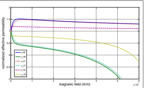
In most cases, ferrite phase shifters are operated at a relatively low magnetic field range. Therefore,it is necessary that the effective permeability behavior is carefully investigated by the change of magnetic field until the positive effective permeability of each material reaches to zero value as shown in Fig. 2.3. In order to describe accurately effective permeability at low static magnetic field region, it is also important to understand the permeability behavior in below saturation magnetization region because the most phase shifting can be achieved with below saturation magnetization. However, to our knowledge, there are few papers in the literature that provide a relationship between the permeability of the ferrite material and the applied magnetic field below saturation magnetization. Moreover, ferrite suppliers do not provide permeability
0 1 2 3 4 5 6 7 8 9 x 10⁵ 0 10 20 30 40 50 60 70 80 90 100
magnetic field (A/m)
nor m aliz ed ef fec tiv e per m eab ilit y ,, +NF ,, +LF ,, +YG
hysteresis traces of their products under a static magnetic field which is necessary to describe effective permeability traces at microwave frequencies.
From the ferrite supplier, it is possible for us to get only an initial permeability value of NF-5000 and YG-1780 as 317 and 134 respectively instead of full permeability traces through B-H tracer. Based on those permeabilities at static magnetic field, the initial permeability of Lithium Ferrite is assumed to be 200 for convenience of calculation. And then the initial permeability values are set under the static magnetic field as constant values until the ferrites are saturated so that we could describe the effective permeability of each ferrite at a given applied magnetic field.
Fig. 2.3 Normalised effective permeability with change of magnetic field at 25GHz for NF-5000, LF-4800 and YG-1780.
0 1 2 3 4 5 6 x 10⁵ -1 -0.5 0 0.5 1 1.5 2
magnetic field (A/m)
nor m aliz ed ef fec tiv e per m eab ilit y , -NF , +NF , -LF , +LF , -YG , +YG
According to Fig.2.3, it is observed that a more permeability split can be achieved with Nickel Ferrite (NF) at static magnetic field below 100,000A/m as this ferrite has a higher saturation magnetization than that of Lithium Ferrite (LF) and Yttrium Ferrite (YG).
2.5 Propagation in transverse magnetization
In rectangular waveguides, a common case is that the ferrite is magnetized in a direction perpendicular to the direction of propagation. When the z-direction is used as the propagation direction of the plane wave and the y-direction is used for the static magnetization, the tensor permeability becomes,
Applying the conditions of a plane wave to the two Maxwell curl equations gives
These results show that two different modes of propagation are separated, one involving magnetic field component and the other involving magnetic components
and although is zero because it is a plane wave. The plane wave described by
eqn. 2.30 is a normal linearly polarized plane wave having the propagation constant. (2.29) (2.30) (2.31) (2.32) (2.28)
It is the mode where the magnetic field component is parallel to the direction of the applied static magnetic field. The other mode is also a plane wave described by (2.29) and (2.31). Eliminating the magnetic field components from those equations gives the propagation constant
Therefore the effective permeabilities for the linear polarized plane waves in transverse magnetization are
As the + and – no longer apply, parallel and perpendicular as superscripts describe better for directions of linear polarization.
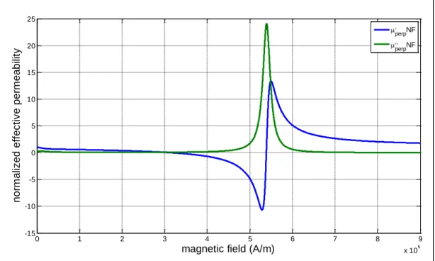
Fig.2.4 shows the normalized effective permeability of transverse magnetized NF- 5000 ferrite material at 25GHz. As compared with Fig.2.2, it is seen that the static magnetic field required for ferromagnetic resonance is decreased by the factor of the saturation magnetization of the ferrite material used.
(2.33)
(2.34)
Fig. 2.4 Normalised effective permeability of transverse magnetized NF-5000 with change of magnetic field at 25GHz
In Fig.2.5, the three ferrites, which have different saturation magnetizations and linewidths, are compared together. It is observed that the ferrite material having higher saturation magnetization requires lower static magnetic field to reach ferromagnetic resonance compared with other ferrite materials that have less saturation magnetization. As explained in the longitudinal magnetization case, it is also observed that the Yttrium ferrite (YF) presents the narrowest linewidth.
0 1 2 3 4 5 6 7 8 9 x 10⁵ -15 -10 -5 0 5 10 15 20 25
magnetic field (A/m)
nor m aliz ed ef fec tiv e per m eab ilit y , perpNF ,, perpNF
Fig. 2.5 Comparison of normalized effective permeability of transverse magnetized ferrites with change of magnetic field at 25GHz
As the phase shifting in ferrite materials is proportional to the change of the effective permeability, Fig. 2.6 illustrates that a ferrite, which has a higher saturation magnetization, can make more permeability change in perpendicular permeability at low static magnetic field at 25GHz. Therefore, it is also expected that more phase shift can be achieved from ferrite materials that have higher saturation magnetization than that of lower saturation magnetization materials in below saturation magnetization region. However, it should be noted from Fig 2.6 that if the saturation magnetization is increased much high, a specific magnetic field value, which brings the effective
0 1 2 3 4 5 6 7 8 9 x 10⁵ 0 20 40 60 80 100 120
magnetic field (A/m)
nor m aliz ed ef fec tiv e per m eab ilit y ,, perpNF ,, perpLF ,, perpYG
permeability to zero, could be too small such that the phase shift cannot be controlled by the static magnetic field intensity.
Fig. 2.6 Normalised effective permeability of transverse magnetized ferrites with change of magnetic field at 25GHz
2.6 Conclusion
In this chapter, the microwave ferrite theory was briefly reviewed and tensor permeability was derived. Both longitudinally magnetized ferrite and transversely magnetized ferrite at microwave frequencies were described and explained in term of loss, magnetization and effective permeability. By solving Maxwell equation, we can get
0 1 2 3 4 5 6 x 10⁵ -0.5 0 0.5 1 1.5
magnetic field (A/m)
nor m aliz ed ef fec tiv e per m eab ilit y , perpNF , perpLF , perpYG
two hands of circular polarized permeabilities. From Fig. 2.3 and Fig. 2.6, it is understood that we can get a more split of circular polarizations at a low static magnetic field if the saturation magnetization value is higher. It is also found that a magnetic field strength of the ferromagnetic resonance of a ferrite is changed by its saturation magnetization value when the ferrite is transversely magnetized whereas that of the ferromagnetic resonance is not affected when the ferrite is longitudinally magnetized.
CHAPTER 3
SUBSTRATE INTEGRATED WAVEGUIDE (SIW)
3.1 Introduction
Waveguide is a traditional transmission line for microwave signal guidance and processing and it is still widely used today for many applications. Various waveguide microwave components such as couplers, detectors, isolators, phase shifters and slotted lines are commercially available for various standard waveguide bands. It is also known that these matured waveguide components present properties of low loss and high power handling. Because of their bulky size, their use is however limited in some of practical applications and it is also difficult to manufacture them in mass production. With trends toward miniaturization and integration, planar transmission line structures such as microstrip and stripline rather than waveguide have been used in many commercial applications. There is, however, still a huge demand for waveguides in loss- and/or power-sensitive applications. Therefore, , it would be much meaningful for microwave applications if we can combine the advantages of planar transmission lines with those of waveguides.
There have been many research activities to develop new platforms of transmission lines to reduce circuit size, simplify manufacture process, lower production cost and maintain high performance. Substrate Integrated Waveguide (SIW) technology is one of
the most popular and the most developed platforms so far as it is quite easy to integrate conventional rectangular waveguide into standard PCB or LTCC [12].
3.2 Rectangular Waveguide
Rectangular waveguide consists of a hollow metal tube of rectangular cross-section which is a closed metal rectangle to transport electromagnetic wave over distances as illustrated in Fig.3.1. The dimensions are a in the direction and b in the direction, with the convention that is [13]. The boundary conditions are that the tangential
component of the electric field must be zero at the four walls of the waveguide: At : and
At : and
At : and At : and
Fig.3.1 Geometry of a Rectangular Waveguide
Due to the single connected conductor geometry, rectangular waveguide does not support the propagation of TEM mode. TE and TM are the modes of propagation in a rectangular waveguide. While, in an SIW only the propagation of TE modes is possible.
Fig.3.2 Various modes in rectangular waveguide [14]
X Y
,
a b Z3.3 Wave Propagation in Waveguide
The geometry of an arbitrary waveguide is shown in Fig. 3.1. This structure is assumed to be uniform in the z direction and infinitely long.
The transverse field components of the TEmn modes can be found by assuming
. Once has been found, the transverse
components are given by
2 2
cos
sin
sin
cos
j z x mn c j z y mn cj
n
m x
n y
E
A
e
k b
a
b
j
n
m x
n y
E
A
e
k a
a
b
2 2sin
cos
cos
sin
j z x mn c j z y mn cj m
m x
n y
H
A
e
k a
a
b
j n
m x
n y
H
A
e
k b
a
b
where integer m and n describe the numbers of variation of the fields along the two transverse coordinates. 2 2 2 2 2 c x y
m
n
k
k
k
a
b
When
0
, The TE modes cannot propagate along the Z axis or the modes are cutoff. 2 2 cm
n
k
k
a
b
(3.1) (3.2) (3.3)Then 2 2
m
n
k
a
b
Equation (3.9) implies that each TE mode has associated with a characteristic cutoff
frequency
f
c m n. . , below which the mode does not propagate. Therefore, the cutoff frequency of each mode is2 2 . .
1
2
2
c c m nk
m
n
f
a
b
The cutoff frequency
f
c m n. . is a geometrical parameter dependent on the waveguide cross section dimensions.3.4 Substrate Integrated Waveguide
Rectangular waveguide is known for its feature properties of low loss and high power handling. However, its bulky structure makes it difficult to fabricate it at low cost and integrate it into planar structure. Table 3-1 shows the comparison of characteristics for several transmission lines [15].
(3.4)
Table 3-1. Comparison of Characteristic for several transmission lines Transmission Line Frequency Range (GHz) Q-factor Power Handling Integration with other components Potential for low cost
production Rectangular
Waveguide <300 High High Poor Poor
Coaxial Line <50 Moderate Moderate Poor Poor
Microstrip
line <100 Low Low Good Good
Slot-line <60 Low Low Good Good
Coplanar
Waveguide <100 Low Low Good Good
Typical integrations from rectangular waveguide to planar structure are bulky and usually require a precise matching process. Furthermore, the planar substrate has to be cut into a specific shape for matching. These constraints make the integration difficult and costly.
A straightforward solution is to integrate the rectangular waveguide into the microstrip substrate. The will surely reduce the Q factor of the waveguide because of dielectric filling and volume reduction. However, the entire circuit including planar circuit, transition and waveguide can be constructed using standard PCB or other planar processing techniques [16].
In general, Substrate Integrated Waveguide (SIW) is the synthesized rectangular waveguide built in the standard PCB or dielectric substrate by placing two discrete metallic via-hole arrays [17] .
A typical geometry is shown in Fig. 3.3 where metallic via-hole arrays work as side walls of the waveguide while the substrate‟s metal cover and ground plane form the
waveguide broad walls. From microwave point of view, the wave propagation is well confined between two arrays of the metallic via holes which can be considered as non-radiating electric walls from the microwave point of view. Each gap between two via holes can be viewed as a holder to support and prevent the waveguide from falling down from the substrate. An appreciative gap size is critical to minimize lateral radiation loss or wave leakage [18].
Fig. 3.3 Configuration of the SIW synthesized by metallic via-hole arrays
3.5 Characterization of Substrate Integrated Waveguide
As mentioned earlier, SIW is composed of two parallel arrays of via holes delimiting the TE10 wave propagation area, as its cutoff frequency is only related to the width a of the waveguide as long as the substrate thickness or waveguide height b is smaller than a.
a g
Parameter a between the two arrays determines the propagation constant of the fundamental mode, and parameters of via holes d and g are set to minimize the radiation loss as well as the return loss.
Though SIW can be characterized by propagation constant, waveguide mode, cutoff frequency and guided wavelength like a conventional rectangular waveguide, it should be noted that SIW has some peculiar physical characteristics as compared with conventional rectangular waveguides.
First, the SIW‟s geometrical parameter a is much larger than b because there is a physical limitation to increase the substrate thickness b. Second, the equivalent waveguide width of SIW, aeff is not the same as a. Therefore, many experiments and
simulations have been conducted to verify value of aeff. One empirical equation to
calculate aeff is given by (3.6) [18].
2 2 1.08 0.1 eff d d a a g a when
1
3
d g
and da
15.SIW can be modeled by rectangular waveguide with an equivalent width and maintains radiation loss at a negligible level, when its geometry parameters meet
5 2 g d g d
where gis the guide wavelength related to aeff .
(3.6)
In order to make an SIW working for K-band applications in this thesis, the cutoff frequency of TE10 mode in SIW is selected about 13.5GHz with the following considerations.
a. TE20 mode should not be excited in SIW.
b. The physical width should be as wide as possible so that ferrite slabs can be inserted.
Figure 3.4 shows the simulation results of SIW designed with the following parameters on Rogers RT/Duroid 6010 with dielectric constant of 10.2. Normally, the dielectric constant of a ferrite material is around 13 ~ 15 and the highest dielectric constant of commercial high frequency laminate materials we can get is 10.2. Therefore, This laminate material can minimize the expected mismatching problem between the dielectric laminate material and the ferrite. In order to avoid any difficulty in inserting ferrite slabs into the SIW, a relatively thick laminate material was chosen so as to make the machining of ferrite materials easier.
Table 3.1 Parameters for Substrate Integrated Waveguide used in Fig 3.3
Width a 4.064mm
Effective width aeff 3.448mm
Via hole diameter d 0.77mm
Gap between vias g 1.016mm
Substrate thickness b 0.635mm
Table 3.1 shows the calculated parameters based on (3.5), (3.6) and (3.7) with the consideration of SIW machining and ferrite slabs. From the calculated effective width of
broad wall, the cutoff frequency of TE10 mode in SIW is about 13.5GHz. This frequency is the optimal frequency that can satisfy both of the above considerations.
Using the parameters in Table 3.1, Fig. 3.4 shows a simulated result of the SIW in Fig 3.3. The simulation result agrees well with the calculated cutoff frequency of 13.5GHz.
Fig. 3.4 Simulation results of the K band SIW
3.6 Transition from Microstrip to SIW
In order to make a good transition from the microstrip to the SIW, first of all, it is necessary to calculate the guide impedance of the SIW which is given by (3.8)
For the calculation of the guide impedance, it is also necessary to calculate the wave
impedance of TE mode which is given by
10 12 14 16 18 20 22 24 26 28 30 -80 -70 -60 -50 -40 -30 -20 -10 0 10 frequency (GHz) m agn it ude (dB) S11 S21 S12 S22 (3.8)
From (3.8) and (3.14), the guide impedance of TE mode of the SIW in Fig 3.3 at
25GHz is calculated to be 38 Ω. Based on the calculated guide impedance, the transition
from 50 ohm microstrip line to 38 ohm microstrip line can be optimized by both
calculation and simulation. Table 3.2 shows the calculated line widths of a 50 ohm
microstrip line and a 38 ohm microstrip line and a quarter wavelength transition length
at 25GHz.
Table 3.2 Calculated parameters for microstrip impedance transition
50 ohm Microstrip Line width w1 0.55mm 38 ohm Microstrip Line width w2 1.25mm
Transition length L 1.8mm
Based on the calculated parameters in Table 3.2, the transition model of 50 ohm
microstrip to the designed SIW is drawn in Fig. 3.5
Fig. 3.5 Transition model of Microstrip to SIW
Figure 3.6 presents the simulated result of the transition model. Therein, more than
20dB return loss over the frequency band of 22GHz to 26GHz has been achieved. From
the simulation, though a better result can be achieved when the first via is located right
on the edge of upper ground edge, the first via hole is placed at 10mil away from the
upper ground edge limited by our PCB fabrication.
w2
w1
Fig. 3.6 Simulated result of the optimized transition model
As the next step, as SIW back to back model, which will be used as the base for the
design of Ferrite phase shifters in this thesis, has been designed and fabricated. Figure
3.7 shows the simulation model and the fabricated model of the SIW with the back to
back transition.
(a) Simulation model
22 22.5 23 23.5 24 24.5 25 25.5 26 -35 -30 -25 -20 -15 -10 -5 0 frequency (GHz) m agn it ude (dB) S11 S21 S12 S22