HAL Id: hal-02526114
https://hal.archives-ouvertes.fr/hal-02526114
Submitted on 8 Dec 2020HAL is a multi-disciplinary open access archive for the deposit and dissemination of sci-entific research documents, whether they are pub-lished or not. The documents may come from teaching and research institutions in France or abroad, or from public or private research centers.
L’archive ouverte pluridisciplinaire HAL, est destinée au dépôt et à la diffusion de documents scientifiques de niveau recherche, publiés ou non, émanant des établissements d’enseignement et de recherche français ou étrangers, des laboratoires publics ou privés.
Distributed under a Creative Commons Attribution - NoDerivatives| 4.0 International License
Carrier Envelope Phase Control of Ultra Short Laser
Pulses
Olivier Gobert, Daniele Rovera, Gabriel Mennerat, Michel Comte
To cite this version:
Olivier Gobert, Daniele Rovera, Gabriel Mennerat, Michel Comte. Linear Electro Optic Effect for High Repetition Rate Carrier Envelope Phase Control of Ultra Short Laser Pulses. Applied Sciences, MDPI, 2013, 3 (1), pp.168-188. �10.3390/app3010168�. �hal-02526114�
applied sciences
ISSN 2076-3417
www.mdpi.com/journal/applsci
Article
Linear Electro Optic Effect for High Repetition Rate Carrier
Envelope Phase Control of Ultra Short Laser Pulses
Olivier Gobert 1, Daniele Rovera 2, Gabriel Mennerat 1 and Michel Comte 1,*
1 CEA-Saclay, IRAMIS, Service des Photons, Atomes et Molécules, 91191 Gif-sur-Yvette, France;
E-Mails: [email protected] (O.G.); [email protected] (G.M.)
2 LNE-SYRTE, Observatoire de Paris-LNE-CNRS-UPMC, 61 avenue de l’Observatoire, 75014 Paris,
France; E-Mail: [email protected]
* Author to whom correspondence should be addressed; E-Mail: [email protected];
Tel.: +33-1-69-08-59-37; Fax: +33-1-69-08-12-13.
Received: 3 December 2012; in revised form: 28 January 2013 / Accepted: 19 February 2013 / Published: 26 February 2013
Abstract: This paper is devoted to analyzing the principle and applications of the linear
electro-optic (EO) effect for the control of the carrier-envelope-phase (CEP). We introduce and detail here an original method, which relies on the use of an EO dispersive prism pair in a compressor-like configuration. We show that, by choosing an adequate geometry, it is possible to shift the CEP without changing the group delay (isochronous carrier-envelope-phase shifter) or change the induced group delay without varying the CEP. According to our calculations, when applying an electric field around 400 V/cm to the rubidium titanyle phosphate (RTP) prisms in a double pass configuration (2 × 40 mm total length), one obtains a CEP shift of π rad at 800 nm without inducing a group delay. In contrast, this CEP shift is obtained for an electric field around 1.4 kV/cm in a RTP rectangular slab of the same total length and, in this case, the group delay is of the order of a few fs.
Keywords: electro-optic; carrier-envelope-phase; ultrafast optics; prism compressor; group
delay; dispersion
1. Introduction
The electric field of a laser pulse is generally described by the product of a wave envelope and a carrier wave. In a dispersive medium, phase and group velocities are different, inducing a slippage of the carrier frequency wave inside the envelope. For ultra-short pulses containing only a few optical cycles, laser-matter interactions can drastically depend on the electric field and not only on its envelope. In this case, controlling the carrier-envelope-phase (CEP) is of prime importance [1–3].
Because of the difference between effective group and phase velocities in laser cavities and of environmental effects, such as vibrations and thermal drift, the generated pulses from ultra-short chirped pulse amplification (CPA) lasers do not have the same CEP. Various methods have been developed in order to obtain, through the use of a fast control loop, a train of CEP stabilized pulses from mode-locked oscillators [4–6]. Different ways also exist to stabilize the CEP of the amplified pulses of a (CPA) laser system seeded by a CEP stabilized mode-locked oscillator. They are mainly based on a slow feedback loop containing a f-2f interferometer [7], a proportional-integral-derivative controller (PID) and a specific CEP correction technique [8].
Examples of those techniques are the use of a pair of wedges to modify the optical path in the dispersive element composing these wedges [9,10], the modification of one parameter of the compressor or of the stretcher (this parameter can be the distance between the gratings) [11,12], the use of an Acousto-Optic Programmable Dispersive Filter (AOPDF) [13–15] or of a 4f system with an adaptive phase modulator device [16].
We recently proposed an original method based on the linear electro-optic (EO) effect in a bulk material (LiNbO3—lithium niobate) [17,18] and successfully applied it to the CEP control of a
titanium-sapphire CPA laser [19] with stabilization performances of the order of those obtained with classical methods. Compared to the main equivalent CEP shifters (as will be detailed at the end of this paper), the major advantages of EO CEP shifters are related to the fact that they do not need mechanical displacements and especially to their high correction bandwidth (>10 kHz). In this paper, we introduce another original method, still based on the use of the EO effect, but in a more complex optical scheme and which relies on the use of an EO dispersive prism pair. While experimental demonstration of CEP shifts and CEP control [17–19] of CPA amplified pulses with a “longitudinal” shifter (simple rubidium titanyle phosphate (RTP) or LiNbO3 rectangular slab) has been proven, no
experimental results will be given here concerning the prism pair EO shifter, which will be the topic of a future paper.
The structure of the paper is the following. We first recall analytical results explaining how a CEP shift can be induced in an EO crystal, the former being linked to the static electric field dependence of the difference between the induced group and phase delays in the crystal. We then give briefly the main experimental results already obtained with CEP shifters consisting of an EO material rectangular slab (that will be called the “longitudinal configuration” of the CEP shifter in the rest of the paper) on which a transverse electric field is applied. The new prism pair configuration is then theoretically detailed, and it is shown that it has many advantages compared to the first set-up, as, in particular, making it possible to shift the CEP without changing the group delay. This may be essential (typically in high resolution pump-probe experiments and especially in experiments making use of attosecond laser pulses) when any
change in timing between pulses is to be avoided. In the last part of the paper, we provide some elements to compare the different solutions for CEP stabilization.
2. EO CEP Shifter
2.1. Theory
Due to the wavelength dispersion of the refractive index in dispersive media, phase and group velocities have, in general, different values. In a crystal with a non-vanishing EO effect, the refractive index can be linearly modulated by an external electric field, E, leading to a variation of the CEP. We consider a laser pulse whose carrier angular frequency is ω0, propagating in a homogeneous dispersive
medium of length, L, which is non-centrosymmetric and exhibits a Pockels effect. This is, for example, the case [17,20] in LiNbO3—uniaxial crystal, crystalline class 3 m or RTP-biaxial crystal orthorhombic
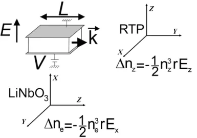
crystalline class mm2—when choosing appropriate directions for the linearly polarized laser field and the applied static electric field. Figure 1 illustrates how the direction of propagation and the polarization of light are to be chosen in practice and how the voltage is to be applied on the crystal in two interesting cases, LiNbO3 and RTP. X, Y and Z are the principal dielectric axes, which are parallel to the
crystallographic axes. With these choices, the variation of the corresponding electric field-dependant refractive index, Δn, is given as a linear function of the EO coefficient, r, and of the electric field, E. We only consider here the case where one can neglect the change in the crystal length, ΔL, due to the inverse piezoelectric effect, as is the case in LiNbO3 and RTP [20–22].
Figure 1. Geometry of the interaction for LiNbO3 and simple rubidium titanyle phosphate
(RTP). X, Y and Z are the principal dielectric axes (parallel to the crystallographic axes).
The CEP shift, CEP, after propagation in the EO crystal when applying the electric field is defined by:
2 ( ) ( ) 0 CEP g E g (1)For the sake of simplicity, we only consider the case when the change of the refractive index due to the linear EO effect depends on a unique r(λ0) coefficient (unclamped EO coefficient at wavelength λ0)
3
0 0 0 0 0 0 1 ( , ) 2 n E n n r E (2)where n0
0 n E0,0
is the refractive index without applied field.Neglecting the inverse piezoelectric effect, one obtains:
0 0 3 2 0 0 0 0 0 0 ( ) 3 2 ( ) ( ) 2 2 CEP n n r n r LE (3)
This phase change is proportional to the length, L, of the crystal and to the electric field, E, applied. It can be used to make an active correction of the CEP and maintain its value constant with a control loop, despite environmental fluctuations.
2.2. Experiments
This section presents previously published results demonstrating the validity of our model and giving an example of the performances obtained with the EO shifter. Equation 3 was checked in [17] for LiNbO3 using a femtosecond 800 nm Ti:S laser source and an f-2f interferometer. The results show a
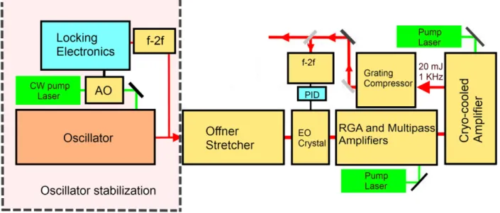
good agreement between theory and experiments. Another approach using spectral interferometry with a broadband laser source [18] was applied to measure CEP shifts and confirmed again, with a better accuracy, the above theory. Stabilization of the CEP (slow loop) of a Ti:S femtosecond laser source was finally demonstrated in [19] with very promising results. The CEP-stable 20W range kHz laser and the EO device for CEP control arrangement is given in Figure 2. In this case, a LiNbO3 crystal longitudinal
EO shifter was used.
Figure 2. Carrier-envelope-phase (CEP)-stable 20 W range kHz laser and LiNbO3
electro-optic (EO) CEP shifter.
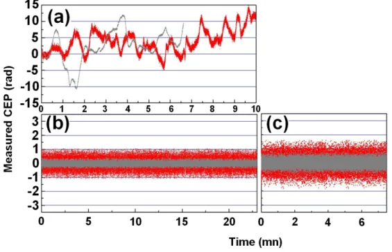
Shot to shot and 10 ms averaged measurement of stabilized CEP drift over 10 min of amplified pulses at 3 W output are compared in Figure 3, with and without slow feedback control.
Figure 3. Shot to shot (red dots) and 10 ms averaged (grey dots) measurement of stabilized
CEP drift over 10 min of amplified pulses at 3 W output (a) without slow feedback control, (b) with EO feedback loop over 25 min leading to RMS CEP noise of, respectively, 320 and 130 mrad and (c) over 7 min of amplified pulses at 20 W output leading to RMS CEP noise of respectively 440 and 250 mrad.
3. Prism Pair CEP Shifter
3.1. Introduction
The EO CEP shifter discussed in the previous part of the document is well-suited to stabilize a high repetition rate CPA Ti:S CEP stabilized mode-locked oscillator system. Nevertheless, for some applications, the CEP shift is not the only relevant parameter. In particular, the electric field-induced group delay Δτg (Δτg = 0 for an isochronous system) and the electric field-induced dispersion ΔФ2 (ΔФ2 = 0 for an iso-dispersive system) may play a role. Furthermore, lowering the applied voltage necessary to obtain the same CEP shift is also clearly of practical interest. Equation 3 shows that the two ways to lower the electric field are to increase the (effective) crystal length or to find a material with optimized characteristics (for example, with a higher EO coefficient).
As can be seen from the theoretical analysis given in paragraph 2.1, the previously described EO CEP shifter configuration is neither rigorously isochronous, nor iso-dispersive, when using LiNbO3 or RTP
crystals. We investigated a combination of two CEP shifters with different crystals, but this set-up proved to be ineffective, as it led to very low CEP shifts when a constant group delay (isochronous system) or a constant dispersion condition (iso-dispersive system) were sought.
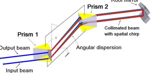
The idea we propose here is to combine material dispersion with angular dispersion, as in the case of a prism compressor [23], and to study the characteristics of an “EO prism compressor”. The prisms are EO crystals (RTP or LiNbO3 for example) on which an electric field is applied (see Figure 4). In this
leads to an S polarization on the prism surfaces and, thus, requires an anti-reflection coating in order to reduce optical losses. The other point, which will be clarified hereafter, concerns the homogeneity of the “static” field in the prisms.
Figure 4. EO prism pair CEP shifter. Yellow parts correspond to gold coating.
3.2. Theory
The induced spectral phase can be written as:
opc
(4)
where Λop is the optical path for a ray of angular frequency, ω, and c is the speed of light in vacuum.
3.2.1. General Configuration
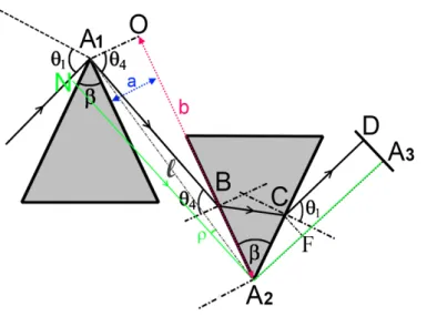
We first consider the general case where the angle of incidence can take any value. As the optical path is obviously invariant for parallel incident rays, we calculate the path of a ray going through the apex of the first prism (Figure 5). For a single pass in the system, it can be written as:
1
op A B BC CD
(5)
Surprisingly, following the method given in [24], a rather simple calculation shows that it can be written in an elegant mathematical form. We consider (Figure 5) a ray NA2 parallel to A1B (NA1 normal
to A1B) intercepting the apex A2 of prism 2. This ray is deviated by prism 2 along the path, A2A3. As A1B
and NA2 are parallel incident rays, the light paths, Λopt = A1BCD and NA2A3, are identical. Let l be the
distance between the apices of the two prisms and ρ the angle, (NA2A1) (Figure 5), the optical pass, Λopt, can be written as:
2 3
cos
op l A A
(6)
If
4
is the angle, (A1A2O), between A1A2 and A1O, one obtains the following relation:
4
2 3 4 4 2 3cos cos cos sin sin
op l A A l l A A
This last equation leads finally to the result:
4 4 2 3
cos sin
op a b A A
(8)
where (Figure 5) θ4 is the external refraction angle at the exit of prism 1 in air, a the slant distance, A1O,
between the output face of prism 1 and input face of prism 2, b the distance, OA2, and A2A3 the distance
between the apex of the second prism and a reflecting mirror (used in a two pass configuration to remove spatial chirp). A2A3 being a constant, we can remove it, and the spectral phase can thus be written:
acos 4 bsin 4
c (9)
This expression is equivalent to that given in [24]. An analogous calculation was also done in [25], but the above expression was not given.
Figure 5. Geometrical arrangement of the EO prism pair.
The group delay, τg, the CEP shift, CEP, and second order dispersion, , have, respectively, the (2) following expression:
2
(2) 2 10a 10b 10 g CEP c (10)Because only the variation of these parameters with the applied static electric field, E, is relevant, we define:
(2) (2) (2) , , ,0 (11a) , , ,0 (11b) , , ,0 (11c) g g gCEP CEP CEP
E E E E E E (11)
The isochronous CEP shifter condition at carrier angular frequency, ω0 (CEP shift without induced
0,
0,
0,0
( , )0 ( ,0) 00 g E g E g E (12)This is to be fulfilled for any value of E. In order to obtain analytical results, we rewrite Equation 2 as:
0 0
( , ) (1 )
n n E n E (13)
By derivation with respect to ω, one gets:
0
dn dn
E
d d (14)
with the following relations:
0 0 2 0 33 ' 0 0 ' 3 33 , 0 (15a) (15b) 2 (15c) n n E n r dn n d dr r
3 2 0 0 ' ' 33 0 0 33 (15d) 3 (15e) 2 d d n n r n n r d (15)Using for the refractive index, a first order Taylor expansion as a function of the static electric field,
E, the isochronous condition leads to the following relation (Appendix I) between a and b:
' 0 0 0 40 ' 2 3 0 0 20 0 0 20 40 sin , cos cos n n b tg a n tg n (16)where θ20 and θ40 are respectively the values of θ2 (internal refraction angle in first prism) and θ4
(external refraction angle in air at the exit of first prism) for E = 0 (Figure 5) and β is the apex angle of the prisms. Similarly, generation of a group delay without variation of the CEP leads to the condition:
0
0
0 0 0 , ,0 , , ,0 0 CEP E E E (17)This situation, that will be called “Pure Group Delay” (PGD) generation in the rest of this paper, implies that a and b are such that (Appendix II):
' 0 0 40 ' 2 3 0 20 20 40 sin cos cos n n b tg a n tg (18)Finally, the iso-dispersive condition being:
0 0 2 2 (2) (2) (2) 0 0 0 2 2 , , 0 ,E , 0 E 0 (19)This leads again to a similar relation. In this case, however, the analytical result is more complex and is not given here for conciseness.
As a first conclusion, we see that for a particular set of the ratio, b/a, that is to say, a specific geometry, it is possible to make the system behave like an isochronous CEP shifter, a PGD generator or an iso-dispersive CEP shifter.
3.2.2. Minimal Deviation Configuration
We now suppose that the incident angle corresponds to the prism minimal deviation at the carrier frequency, ω0. This condition, which gives the highest angular dispersion, can be written as:
1 Arcsin n0sin 2
(20)
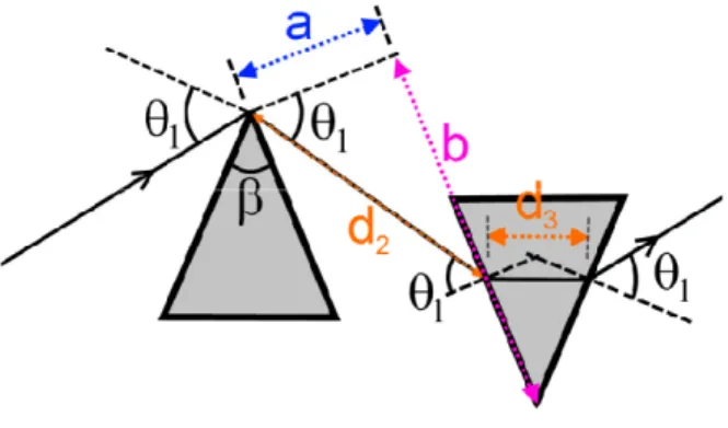
As these parameters are more relevant from an experimental point of view, instead of using the parameters, a and b, we now switch to the parameters, d2 and d3, corresponding, respectively, to the
distances covered between prism 1 and 2 in air and to the total path inside the prisms for the ray at the carrier frequency (Figure 6). The spectral phase takes the form (Appendix III):
4
2 1 4 3 sin , , cos , 2sin / 2 E E d E d c (21)We will now express the results in the particular case of central wavelength, λ0, corresponding to the
central angular frequency,0 2 c 0, and using λ instead of ω. Equation 21 becomes (Appendix IV):
3 0 0 0 2 ,E d n E (22)This shows that, at central wavelength, λ0 the variation of the spectral phase with respect to the
applied electric field does not depend on the distance, d2, nor on the apex angle, β.
Figure 6. Geometrical arrangement of the EO prism pair CEP shifter at prism minimal deviation.
The group delay variation with respect to the applied electric field is written:
2 0 0 0 2 2 1 0 2 0 0 3 0 3 0 0 sin / 2 4 cos ( ) tan 2 g dn n d d E c dn d n d d n d d (23)where λ is the wavelength corresponding to the angular frequency, ω, and where we use the derivatives taken with respect to the wavelength, λ, instead of ω.
Contrary to the case of the variation of the spectral phase with the electric field, the variation of the group delay with the field depends on d3 and d2. Analytical expression of the group dispersion with
respect to the electric field can also be derived, but, as in the general configuration, is not given here for conciseness.
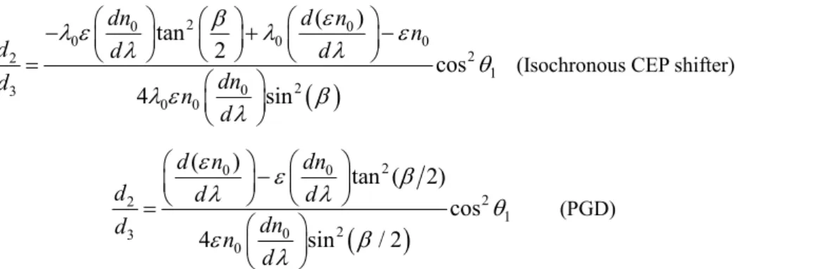
Analytical expressions of the ratio, d2/d3, at 0 for isochronous CEP shifter and PGD generator
configuration are, respectively, given below:
2 0 0 0 0 0 2 2 1 2 0 3 0 0(Isochronous CEP shifter)
( ) tan 2 cos 4 sin dn d n n d d d dn d n d (24)
2 0 0 2 2 1 2 0 3 0 (PGD) ( ) tan ( 2) cos 4 sin / 2 d n dn d d d dn d n d (25)When the isochronous CEP shifter configuration is chosen, the variation of the CEP is equal to the variation of the spectral phase with the electric field, which is given by Equation 22.
Another interesting parameter to evaluate is the group-delay dispersion (GDD) induced on the beam by the two prism compressor for E = 0 at 0. It can be written in our notations as:
2 2
2 2 2 0 0 2 2 0 0 2 3 (2) 0 0 2 2 2 3 2 1 0sin 2 sin 2 cos 2
sin 2 2 cos sin dn d n dn n d d d d d c n (26)
From this expression, we deduce the ratio, d2/d3, for which the system introduces no dispersion
(i.e., (2)0) at 0 :
2 2 2 0 2 0 2 1 0 2 2 2 3 2 0 0cos sin 2 cos 2
sin dn d n n d d d d dn n d (27)
Analytical results were checked numerically with a ray tracing program.
3.3. RTP Prism Pair CEP Shifter
This paragraph presents numerical results obtained in RTP crystals. The geometry corresponds to Figure 7, with the path length of the ray at the carrier frequency chosen equal in the two crystals.
This geometry is in practice to be preferred in order to obtain an homogeneous “static” electric field in the crystal (which would not be the case at the tip of a prism). The RTP Sellmeier formula for the refractive index is taken from [26] and the wavelength dispersion of the EO coefficients from [20].
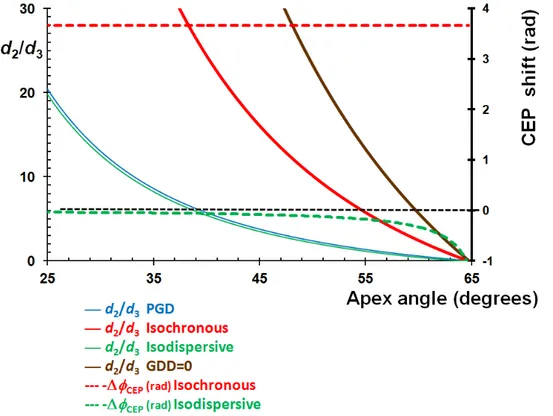
Figure 8 plots the ratio, d2/d3, versus the apex angle, β, of the prisms when the isochronous
blue) and the iso-dispersive conditions ( (2)
(2)
(2)
0 0,E 0,0 0
, thin green) are imposed. This gives a means of comparing the performances of each configuration. The thick brown line corresponds to a zero dispersion condition when no electric field is applied ( (2)
0,E 0 0
) to the set-up.
Figure 7. Proposed practical geometry for the prism pair CEP shifter set-up.
Figure 8. Ratio, d2/d3, versus apex angle for different configurations and corresponding CEP shift.
It appears that it is not possible to obtain simultaneously an isochronous and iso-dispersive system, nor an isochronous system without dispersion. In the isochronous configuration, the set-up introduces a positive dispersion (as the red curve is on the left of the brown curve, which corresponds to a zero dispersive system at zero electric field). Figure 8 also shows that the PGD configuration (no CEP shift) is very close to the iso-dispersive configuration. This implies that the iso-dispersive configuration should be generally inefficient as a CEP shifter (i.e., will require a far higher voltage to generate the same CEP shift than the isochronous configuration). This is confirmed bylooking at the CEP shift, which is plotted (for d3 = 40 mm and E = 1 kV/cm) on the same graph in the iso-dispersive configuration (dotted green
line). Finally, the dotted red line curve (which corresponds to the isochronous CEP shift as a function of β) illustrates the fact that, in the isochronous configuration, the CEP shift (at central frequency ω0 is
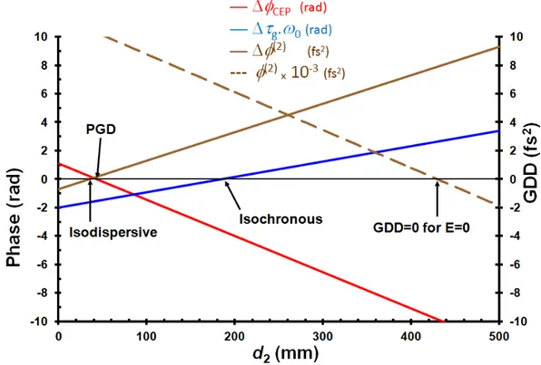
In order to have an idea of the practical values of d2 corresponding to each configuration, Figure 9
plots the induced CEP shift (red line), the induced group delay (i.e., 0 g—blue line) and the induced GDD (brown line) at central frequency, ω0, as a function of d2. The group delay dispersion, (GDD) (2)
for E = 0 is also plotted (dotted brown line). These results are obtained in the case of an apex angle of the prisms, 56.5, a total path length, d
3 = 40 mm, at 800 nm and a static electric field, E = 1 kV/cm.
Figure 9. CEP shift, Δg ω0 phase, (2) and introduced by a RTP prism pair CEP (2)
shifter versus d2 for the following parameters (apex angle 56.5 , d3= 40 mm,
E = 1 kV/cm; a value E = 0 kV/cm is assumed for the calculation). (2)
This graph shows again that PGD and iso-dispersive configurations correspond to nearly the same value of d2 and that the CEP phase shifter is not efficient in the iso-dispersive configuration. One can also
conclude that at fixed CEP shift and, for a given pair of prisms, increasing d2 (i.e., the distance between
the prisms) can increase the CEP shift range or reduce the electric field. This, however, cannot be done while maintaining the isochronous condition. In any case, d2 is limited by the size of the beam on the
second crystal, which depends on its spectral extent.
3.4. Comparison between Different CEP Shifters
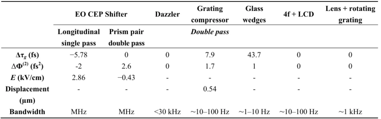
As different CEP shifters based on various physical phenomena can be found in the literature, it is interesting to compare their performances with the EO CEP shifters. In order to do so, we have restricted ourselves to five systems. These are the AOPDF [4,15], the grating compressor [11,12], the glass wedges system [9,10], the 4f + LCD system [16] and the lens/rotating grating system [27]. Mainly, we chose to compare the induced group delay, Δτg, and the induced GDD of each system and added, when significant, specific data, such as the mechanical displacement for the grating compressor and the
electric field for the EO devices. Table 1 gives these parameters, when required, for all the systems, for a CEP phase shift of π radians at a wavelength of 800 nm. In the case of the EO CEP shifters, the single pass configuration and the double pass two-wedged crystal isochronous configuration are selected for comparison and a single pass propagation length, L = 40mm, chosen in RTP for the central wavelength rays. This corresponds to RTP crystal lengths, which are commercially available and that lead to relevant CEP shift at moderate values of the electric field. 1,200 grooves/mm gratings were considered at 37° incidence for the grating compressor. Concerning the glass wedge system, the basic configuration described in [10] is considered, with a displacement of two silica wedges perpendicular to the beam axis to vary the thickness of silica. We also give an estimate of the correction bandwidth, defined as the inverse of the time needed to change from one CEP value to another.
Table 1. Comparison between different CEP shifters.
EO CEP Shifter Dazzler Grating
compressor Glass wedges 4f + LCD Lens + rotating grating Longitudinal single pass Prism pair double pass Double pass Δτg (fs) −5.78 0 0 7.9 43.7 0 0 ΔФ(2) (fs2) -2 2.6 0 1.7 1 0 0 E (kV/cm) 2.86 −0.43 - - - - - Displacement (µm) - - - 0.54 - - - Bandwidth MHz MHz <30 kHz ~10–100 Hz ~1–10 Hz ~10–100 Hz ~1 kHz
It is to be noted that the above bandwidths concerning the grating compressor, the glass wedges and the 4f+LCD systems are only to be considered as “typical values”. In practice, the effective bandwidth depends on the specific configuration, and the main result to be kept in mind is that their response time is considerably lower than those of the Dazzler or the EO CEP shifter, for example.
4. Conclusions
Compared to the longitudinal EO CEP shifter, the major advantages of the new configuration described here are the possibility to work without induced group delay and the lower static electric field needed for a given CEP shift. In addition, the system can also be used to control a group delay without shifting the CEP (PGD generator). The combination of two such systems should allow us to control separately the CEP and the group delay at a very high speed. The induced GDD can be estimated from table 1 and can be neglected, provided that the condition, 2 2 / 10
p
, is verified. This shows that corrections can be made, even on very short pulses, the most important point being the ability of the system to correct the CEP at a very high speed, which can very probably be extended to the 100 kHz range.
The EO phase shifter cannot be used to stabilize the CEP of the optical pulse train outside the mode-locked (ML) oscillator (see Appendix V). This new set-up should be well suited to stabilizing the CEP of the amplified pulses of a chirped pulse amplification (CPA) laser system seeded by a CEP
stabilized mode locked oscillator (slow feedback loop), as was demonstrated in the case of the longitudinal EO shifter [19].
The authors strongly believe that this type of system could be of interest for different applications, like coherent control, polarization shaping, stabilization of interferometric systems, coherent combination of fiber amplifiers and frequency synthesizers.
Acknowledgments
This work was done within the framework of the IMPULSE laboratory, which is a joint R & D laboratory associating CEA Saclay and Amplitude Technologies.
Conflict of Interest
The authors declare no conflict of interest.
Appendix 1: Derivation of the Isochronous Condition (General Case)—Equation 16
As it is obvious that the path length is the same for any ray having the same incident angle, θ1, on the
first prism, calculations are done in the particular case of a ray intercepting the apex, A1, of prism 1, as
shown on Figure 5.
Figure 10. Incident and refracted angles of the prism pair set-up in the general case.
However, as it is easier to understand the significance of each angle in the general case, we add Figure 10, where the following angles appear:
‐ β apex angle of the prisms; ‐ θ1 incident angle on prism 1;
‐ θ2 refracted angle in prism 1;
‐ θ3 incident angle on the output face of prism 1;
‐ θ4 refracted angle after prism 1 (in air);
‐ θ5 incident angle on prism 2;
‐ θ6 refracted angle in prism 2;
Clearly, the same angles can be defined in Figure 5. Using Snell’s law at each interface with elementary geometrics, the following relations are obtained:
(A.1)
Equation 9 gives the spectral phase, , as a function of geometrical parameters, a,b, and the angle, θ4 (Figure 5). The variation of the group delay, Δτg, when applying the electric field, E, is given by:
(A.2) This equation can be rewritten as:
(A.3) where:
(A.4)
In these equations, θ4 and θ40 are, respectively, the output angle of prism 1, as defined in Figure 5,
when an electric field is applied and when it is not. The isochronous condition corresponds to Δτg = 0
(no group delay variation due to the application of the electric field).
1.1. Calculation of A
Approximate expressions as a function of E are now to be used. Elementary mathematics show that to the first order of the electric field E:
(A.5)
where we used the following definitions:
(A.6)
Parameter A can be calculated to the first order of E using the set of Equation A.1:
1 2 4 2 3 2 6 3 7 1 sin sin sin sin n n
, ,0
g E g c A B
40 4 40 4 40 4 40 4sin sin cos cos
sin sin cos cos
A b a B b a
4 40 0 20 40 4 40 0 20 40 2 20 2 2 20 20 sin sin sin cos sin sin cos cos cos cos sin sin 1cos cos 1 tan
n E n E E E
0 2 0 1 with 2 n n E n r (A.7)
This can be rewritten as:
(A.8) It is easy to show that (See Figure 5), the light pass in prism 2 without electric field applied, has the following form:
(A.9)
1.2. Calculation of B
Using Snell’s law in prism 1, one has:
(A.10) Differentiation of Equation A.10 leads to:
(A.11)
This gives an expression for B:
(A.12)
where x3 is the light pass in prism 2 when the electric field is applied:
(A.13)
1.3. Group Delay
Equation A.3, A.8 and A.12 lead to the group delay variation:
(A.14) We now use the first order expression of n, Equation A.6, as a function of E to write:
40 4 40 4 40 0 0 20 20 40 0 0 40 20sin sin cos cos
sin sin sin
cos cos cos
sin tan cos A b a bn E an E n an b E 0 30 A n x E 30 x BC
30 40 20 sin tan cos x b a 4 2 sin nsin( ) 4 4 2 40 0 40 20 sin cos cos sin cos cos n n
0 4 40 2 20 0 30 3 sin sin tan tan cos cos n n B a b a b n n x x
3 4 2 sin tan cos x b a
' '
30 0 2 0 30 1 g c x n x n n x E (A.15)
We then need an approximate expression of x3 to the first order in E as a function of x30. This is
obtained using Equation A.13 and the set of Equation A.5. One obtains:
(A.16)
Γ and γ are defined by:
(A.17)
Inserting Equation A.17 in Equation A.14 and using Equation A.16, one obtains the first order in E: (A.18) where ε and η are given by Equation 15.
The isochronous condition leads to a relation between x30 and a, which does not depend
on E. Using Equation A.9 and Equation A.18, one obtains Equation 16.
Appendix 2: Derivation of the Pure Group Delay Condition (General Case)—Equation (18)
The “pure group delay” condition, as defined in section 3.2.1, corresponds to the situation where there is no CEP shift induced by the prisms (and, thus, only a group delay). This condition can be written using the spectral phase as:
(A.19) Using Equation 9, one obtains:
(A.20) This equation can be rewritten using Equation A.8 and A.18 as:
(A.21) This leads to:
(A.22) Again, using Equation A.9, Equation 18 is obtained.
0 2 0 0 ' ' 0 0 (A.15.a) with 3 see equation (15.e) (A.15.b)2 n n E d n n rn n r d
2 2 0 3 30 2 3 30 20 20 40 30 30 sin tan cos cos an x x x E x x E 2 0 2 3 20 40 2 20 sin cos cos tan an
' ' 0 0 0 30 g c n n n x E
g 0
0
0
0 0 0 , ,0 , , ,0 0 CEP E E E
0,
sin 40 sin 4
cos 40 cos 4
0CEP E b a c g A c g
' '
0 30 0 0 0 30 0 n x E n n n x E ' 0 30 ' 0 n x n Appendix 3: Derivation of Equation 21
We first need to consider Figure 6 in order to obtain a and b as a function of d1 and d2. We immediately see that:
(A.23)
Replacing these expressions in Equation 9, one obtains:
(A.24)
This last equation is equivalent to Equation 21
Appendix 4: Derivation of the Equation 22
Equation 22 gives the spectral phase in the case of minimum deviation and at central frequency, . This relation is obtained using Equation 21, which is valid for any frequency. At central frequency, as represented on Figure 6, the following relations take place:
(A.25) Taking into account Equation A.25 in Equation 21 at and using the central wavelength, , instead of the central frequency, ω0, one obtains immediately Equation 22.
Appendix 5: Discussion on the Possibility to Stabilize the CEP of a ML Laser Oscillator with an EO System, Outside the Oscillator Cavity
We discuss here the ability of an EO prism pair system to stabilize the CEP of a mode-locked (ML) laser oscillator. The electric field at the output of a mode locked system can be written:
(A.26) In this formula, is the period between two pulses, ω0 is the circular carrier wave frequency
and ΔCE is the phase slippage (modulo 2 between two pulses. Applying Fourier transform and Fourier series theory, one obtains the following expression [28]:
(A.27) where δ is the Dirac function. This corresponds, as is well known, to a frequency comb, with frequencies given by: (A.28) 2 1 3 2 1 cos sin 2sin( / 2) a d d b d
3 2 1 4 2 1 4 3 2 1 4 4cos cos sin sin
2sin( / 2) cos sin 2sin( / 2) d c d d d c d 0
4 0 1 0 2 0 / 2 0 0
0 0 0 ( ) i t n n ce p n E t
E t n e 1/ frep
i 0
2
p c ce m E e E
m 0 e 2 m ce m f mfr p A method was recently proposed and demonstrated to stabilize the CEP of the optical pulse outside the oscillator cavity [29].
Figure 11. Application of sinusoidal phase modulation at frep.
This method is based on an acousto-optic device in order to shift the frequency comb. As EO systems are currently used in the ns domain as frequency shifters through a linear temporal phase sweep, it is natural to wonder whether an EO phase CEP shifter could be used to stabilize the CEP of the pulse train outside the ML oscillator by shifting the comb frequencies. To our knowledge, the only way to apply a linear temporal phase shift on every pulse is to use a sinusoidal phase modulator at frequency frep (or an
integer multiple of frep), as shown on Figure 11. The electric field at the output of the modulator can then
be written:
(A.29) where Γ is the amplitude modulation index, which depends linearly on the radio frequency (RF) electric field applied to the crystal, and ωrep is the angular frequency corresponding to frep. Applying the Anger-Jacobi development [30] to the last term of Equation A.29 leads to:
(A.30)
In the spectral domain, the electric field has the following form:
(A.31) where the symbol * stands for the convolution product and Jk are Bessel functions. This last expression can be written as:
(A.32)
This shows that the EO device shifts the spectral envelope, but not the frequencies of the comb, as is the case with the acousto-optic device. This can be easily understood if one considers, on one side, a single pulse on which a linear temporal phase is applied and whose spectrum is shifted by Γωrep, and, on
0 0 0 sin ( ) i t n n ce i rept p n E t E t n e e
0 0 0
( ) i t n n ce ik rept p k n E t E t n e J e
0
0 0 * i p rep k rep m E e E m J k
k
p
0 rep
rep 0
k m E J E k m
the other side, a single mode of the comb, whose temporal extension is infinite and which experiences a sinusoidal phase modulation, giving rise to adjacent modes separated by a multiple of ωrep. This shows that it is not possible to stabilize in this way the CEP of the optical pulse train outside the ML oscillator with our EO device.
References
1. Goulielmakis, E.; Schultze, M.; Hofstetter, M.; Yakovlev, V.S.; Gagnon, J.; Uiberacker, M.; Aquila, A.L.; Gullikson, E.M.; Attwood, D.T.; Kienberger, R.; et al. Single-cycle nonlinear optics.
Science 2008, 320, 1614–1617.
2. Krausz, F.; Ivanov, M. Attosecond physics. Rev. Mod. Phys. 2009, 81, 163–234.
3. Nisoli, M.; Sansone, S. New frontiers in attosecond science. Prog. Quantum Electron. 2009, 33, 17. 4. Reichert, J.; Holzwarth, R.; Udem, T.; Hänsch, T.W. Measuring the frequency of light with
mode-locked lasers. Opt. Commun. 1999, 172, 59–68.
5. Telle, H.R.; Steinmeyer, G.; Dunlop, A.E.; Stenger, J.; Sutter, D.H.; Keller, U. Carrier-envelope offset phase control: A novel concept for absolute optical frequency measurement and ultrashort pulse generation. Appl. Phys. B 1999, 69, 327–332.
6. Jones, D.J.; Diddams, S.A.; Ranka, J.K.; Stentz, A.; Windeler, R.S.; Hall, J.L.; Cundiff, S.T. Carrier-envelope phase control of femtosecond mode-locked lasers and direct optical frequency synthesis. Science 2000, 288, 635–639.
7. Kakehata, M.; Takada, H.; Kobayashi, Y.; Torizuka, K.; Fujihira, Y.; Homma, T.; Takahashi, H. Measurements of carrier-envelope phase changes of 100-Hz amplified laser pulses. Appl. Phys. B
2002, 74, S43–S50.
8. Baltuška, A.; Paulus, G.G.; Lindner, F.; Kienberger, R.; Krausz, F. Femtosecond Optical
Frequency Comb Technology. Principles, Operation and Application; Ye, J., Cundiff, S., Eds.;
Springer Science+Business Media: New York, NY, USA, 2005; Chapter 10, pp. 263–307.
9. Apolonski, A.; Poppe, A.; Tempea, G.; Spielmann, C.; Udem, T.; Holzwarth, R.; Hänsch, T.W.; Krausz, F. Controlling the phase evolution of few-cycle light pulses. Phys. Rev. Lett. 2000, 85, 740–743.
10. Grebing, C.; Görbe, M.; Osvay, K.; Steinmeyer, G. Isochronic and isodispersive carrier-envelope phase-shift compensators. Appl. Phys. B 2009, 97, 575–581.
11. Treacy, E.B. Optical pulse compression with diffraction gratings. IEEE JQE 1969, QE-5, 454–458. 12. Chang, Z. Carrier-envelope phase shift caused by grating-based stretchers and compressors. Appl.
Opt. 2006, 45, 8350–8353.
13. Tournois, P. Acousto-optic programmable dispersive filter for adaptive compensation of group delay time dispersion in laser systems. Opt. Commun. 1997, 140, 245–249.
14. Crozatier, V.; Forget, N.; Oksenhendler, T. Toward Single Shot Carrier-Envelope Phase Stabilization for Multi kHz Ultrafast Amplifiers. In Proceedings of the Lasers and Electro-Optics
Europe (CLEO EUROPE/EQEC), 2011 Conference on and 12th European Quantum Electronics Conference, Munich, Germany, 22–26 May 2011.
15. Canova, L.; Chen, X.; Trisorio, A.; Jullien, A.; Assion, A.; Tempea, G.; Forget, N.; Oksenhendler, T.; Lopez-Martens, R. Carrier-envelope phase stabilization and control using a transmission grating compressor and an AOPDF. Opt. Lett. 2009, 34, 1333–1335.
16. Kakehata, M.; Takada, H.; Kobayashi, Y.; Torizuka, K. Generation of optical-field controlled high-intensity laser pulses. J. Photochem. Photobiol. A 2006, 182, 220–224.
17. Gobert, O.; Paul, P.M.; Hergott, J.F.; Tcherbakoff, O.; Lepetit, F.; D'Oliveira, P.; Viala, F.; Comte, M. Carrier-envelope phase control using linear electro-optic effect. Opt. Express 2011, 19, 5410–5418. 18. Gobert, O.; Fedorov, N.; Tcherbakoff, O.; Hergott, J.F.; Perdrix, M.; Lepetit, F.; Guillaumet, D.; Comte, M. Measurement of Carrier-Envelope-Phase shifts using spectral interferometry with a broad frequency laser source. Opt. Commun. 2012, 285, 322–327.
19. Hergott, J.-F.; Tcherbakoff, O.; Paul, P.-M.; Demengeot, Ph.; Perdrix, M.; Lepetit, F.; Garzella, D.; Guillaumet, D.; Comte, M.; D’Oliveira, P.; et al. Grating based, chirped-pulse amplified laser, using Electro-Optic effect in a LiNbO3 crystal. Opt. Express 2011, 19, 19935–19941.
20. Gobert, O.; Fedorov, N.; Mennerat, G.; Lupinski, D.; Guillaumet, D.; Perdrix, M.; Bourgeade, A.; Comte, M. Wavelength dispersion measurement of electro-optic coefficients in the range of 520 to 930 nm in rubidium titanyl phosphate using spectral interferometry. Appl. Opt. 2012, 51, 594–599. 21. Weis, R.S.; Gaylord, T.K. Lithium niobate: Summary of physical properties and crystal structure.
Appl. Phys. A 1985, 37, 191–203.
22. Andrushchak, A.S.; Mytsyk, B.G.; Demyanyshyn, N.M.; Kaidan, M.V.; Yurkevych, O.V.; Solskii, I.M.; Kityk, A.V.; Schranz, W. Spatial anisotropy of linear electro-optic effect in crystal materials: I Experimental determination of electro-optic tensor in LiNbO3 by means of
interferometric technique. Opt. Lasers Eng. 2009, 47, 31–38.
23. Martinez, O.E.; Gordon, J.P.; Fork, R.L. Negative group-velocity dispersion using refraction.
JOSA A 1984, 1, 1003–1006.
24. Fork, R.L.; Martinez, O.E.; Gordon, J.P. Negative dispersion using pairs of prisms. Opt. Lett. 1984,
9, 150–152.
25. Arissian, L.; Diels, J.C. Carrier to envelope and dispersion control in a cavity with prism pairs. PRA
2007, 75, 1–10.
26. Mikami, T.; Okamoto, T.; Kato, K. Sellmeier and thermo-optic dispersion formulas for RbTiOPO4.
Opt. Mater. 2009, 31, 1628–1630.
27. Zvyagin, A.V.; Sampson, D.D. Achromatic optical phase shifter-modulator. Opt. Lett. 2001, 26, 187–189.
28. Cundiff, S.T. Phase stabilization of ultrashort optical pulses. J. Phys. D 2002, 35, R43–R59. 29. Koke, S.; Grebing, C.; Frei, H.; Anderson, A.; Assion, A.; Steinmeyer, G. Direct frequency comb
synthesis with arbitrary offset and shot-noise-limited phase noise Nat. Photonics 2010, 4, 462–465. 30. Arfken, G.B.; Weber, H.J. Mathematical Methods for Physicists, 6th ed.; Elsevier Academic Press:
Burlington, MA, USA, 2005; p. 687.
© 2013 by the authors; licensee MDPI, Basel, Switzerland. This article is an open access article distributed under the terms and conditions of the Creative Commons Attribution license (http://creativecommons.org/licenses/by/3.0/).