Creatr: A Generic Graphical Distributed Debugger with
Language Support for Application Interfacing
by
Shakil A. Chunawala
Submitted to the Department of Electrical Engineering and Computer Science in partial fulfillment of the requirements for the degrees of
Master of Science
and
Bachelor of Science in Computer Science and Engineering
at the
MASSACHUSETTS INSTITUTE OF TECHNOLOGY September 1994
( Shakil A. Chunawala, MCMXCIV. All rights reserved.
The author hereby grants to MIT permission to reproduce and to distribute publicly paper and electronic copies of this thesis document in whole or in part.
Author ... ... . .- ...-.
-.
...-.
.. . . . . .- . ..
.
.
Department of Electrical Engineering and Computer Science
June 10, 1994
Certified by (I/ ... ....
.
... ..
..
...
.
...
Certifiedby..(
.
John
Wroclawski
Research Scientist, MIT Department of EECS
Certified
by
....
.,.
-...
.
Jay Thomas
Hardware Toolsrnd CBX Hardware/Firmware Manager, ROLM
Accepted by...
_p .Tf7E
'
sFtom
Chair,
Dp
e C oFrederic
R.
Morgenthaler
Creatr: A Generic Graphical Distributed Debugger with
Language Support for Application Interfacing
by
Shakil A. Chunawala
Submitted to the Department of Electrical Engineering and Computer Science
on June 10, 1994, in partial fulfillment of the requirements for the degrees of
Master of Science
and
Bachelor of Science in Computer Science and Engineering
Abstract
High level debugging tools which can model system-level views of programs have proven very useful to developers of distributed systems. Unlike source-level debug-gers, system-level debugger allow programmers to quickly gain an understanding of how the various parts of a system are interacting by displaying information at a higher granularity. Traditionally, such tools have received limited use due to target depen-dencies. When the application changed, existing tools were unable to handle the new context, thus requiring the development of new tools, or major rewrites of existing tools.
This thesis introduces Creatr, a tool for debugging EventFlow systems. Creatr targets a specific programming model, EventFlow, but makes limited assumptions about how various systems make use of this model. Instead, Creatr provides
linguis-tic support to allow the user to define how a given target application maps to the
general model. By providing a hook library, users can quickly interface Creatr to a wide range of applications. Creatr also provides support for user-defined data
visu-alization and information filtering. By abstracting out target dependencies, Creatr
provides a more flexible and reusable solution to system-level debugging than has been previously available.
Thesis Supervisor: John Wroclawski
Title: Research Scientist, MIT Department of EECS
Thesis Supervisor: Jay Thomas
Acknowledgments
Many people have been instrumental in the development of this thesis. Foremost, I would like to thank Ken Duda. He provided interesting insight which helped guide the development of the ideas presented in this thesis and assisted in resolving various implementation problems. Kevin Raper, Mark Clark, and Monica Seles also deserve
thanks. Creatr's success is attributable to the valuable end-user input they provided.
I would also like to thank my advisor, John Wroclawski for his unbelievable patience with me. Credit goes to Jerry Saltzer and Jay Thomas for acting as go-betweens when company policies were in conflict with MIT requirements.
Finally, I need to thank my family. My education would not have been possible
without the moral and financial support of my parents, Jamil and Shaista. Every day, I read the paper or look at the job market and realize that they knew what they
were talking about: education does what no other investment can - it reduces risk while increasing expected returns.
Contents
1 Introduction 2 Background 2.1 Related Work . . . . 2.1.1 Behavioral Abstraction 2.1.2 Interactive Debugging 2.2 Common Problems ... 2.3 Differences in Creatr ...3 Goals and Overview
3.1 Goals. ...
3.1.1 System-Level Debugger ...
3.1.2 User-Defined Event Granularity/Target Independence. 3.1.3 Portability/Reuseability ...
3.1.4 Graphical and Textual Display ... 3.1.5 Customization. ... 3.2 Overview . ... 3.2.1 EventFlow Modeling . . . . 3.2.2 Customization Facilities ... 4 Design 4.1 High-Level View ... 4.2 Back-End ... 4.2.1 Event Mappings . . . 8 11 11 11 12 13 14 15 15 15 16 17 18 19 20 21 23 26 26 28 28 . .. . . . . . . .
...
...
. . . . . . . . . . . . ....
...
4.2.2 Event Delivery ... 4.2.3 Time Sequencing of Events. 4.3 Engine ...
4.3.1 Object Database ...
4.3.2 Graphical User Interface . .
4.4 Front-End ... 4.4.1 Visualization. 4.4.2 Filtering ... 4.4.3 Message Formatting .... 5 Languages 5.1 Linguistic Style ...
5.2 Event Definition Language(EDL) ....
5.2.1 Timeline-Events . ... 5.2.2 Message-Events ... 5.2.3 Static Events ... 5.3 Visualization Language(VL) ... 5.3.1 Control Flow. 5.3.2 Drawing Primitives ...
5.3.3 Event Referencing and Extensions 5.3.4 Example Routines ...
5.4 Message Formatting Language(MFL) . .
5.4.1 Control Flow.
5.4.2 Regular Expression Matching . .
5.4.3 Report Generation ... 5.5 Filtering Language(FL) ... 5.5.1 Filter Primitives ... 6 Usage 6.1 Target Model ... 6.2 Event Definitions ... 29 31 32 33 34 34 36 38 40 42 42 43 44 45 46 47 47 47 50 52 52
...
52
53 54 55 55 57 57 58...
...
...
...
...
...
...
...
...
. . . . . . . . . . . . . . . . . . . . . . . . . . . . . . . . . . . . . . . . . . . . . . . .6.3 Customizations ... 6.3.1 Visualization .... 6.3.2 Message Formatting 6.3.3 Filtering ... 6.4 Comments ... 7 Evaluation 7.1 Linguistic Support ... 7.1.1 Performance Constraints on VL
7.1.2 Overall Linguistic Style . . . .
7.1.3 Expressiveness vs. Ease of Use .
7.2 Portability. ... 7.3 Application Domain ... 7.4 Other Issues . . . . 8 Conclusion 8.1 Future Work . . . . A Visualization Code 60 60 61 64 66 67 67 67 69 69 70 71 73 75 75 77 . . . . . .
...
. . . . . ....
. .. . . ....
List of Figures
3-1 Graphical vs. Textual Display ... ... 19
3-2 System Level Views ... ... 21
3-3 The EventFlow Model ... 22
4-1 Creatr Toolkit . . . ... 27
4-2 Creatr Graphical User Interface ... 35
4-3 Basic Timeline and Message Visualization ... 37
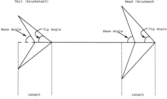
5-1 Properties of Line End-Points ... 49
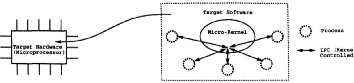
6-1 Target vs. Simulated Environment ... 58
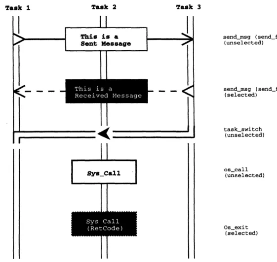
6-2 Graphical Realization of Events ... .. 61
Chapter 1
Introduction
The basis of this thesis is that good debugging tools are critical to reducing software development cycles. Increasing program complexities and performance demands have forced developers to adopt new languages and programming methodologies. However, debuggers have not kept pace with this migration. This thesis studies the problem of extending debugging capabilities to meet the demands of the latest development pro-cesses. In particular, a generic debugger is introduced. This debugger addresses some of the problems associated with a recent class of debuggers: system level debuggers.
Currently there are three general classes of software debugging tools: object-level, source-level, and system-level. Object-level debuggers are used to debug programs written in a machine's native language. They have an instruction-set level control granularity. They allow users to view and/or modify the stack, registers, and memory. While a native language is useful and often required to write programs such as device drivers or to make performance optimizations specific to a given machine, it is very difficult to develop software of any complexity at this level.
High-level languages mask machine-specific dependencies and allow programmers
to deal with computation issues instead. Such issues include control flow and data ma-nipulation. Furthermore, such languages provide a barrier between the programmer
and the machine, allowing for portable code development. Debuggers which provide control granularity consistent with high-level languages are often called source-level debuggers. They allow developers to single-step through source code (code written
in the high level language), view/modify variables (instead of specific memory lo-cations), set source-level breakpoints, etc. User control of programs shifts from an object-level to a source-level viewpoint.
High-level languages increase the application domain by abstracting out certain object-level complexities. However, large software systems continue to be unmanage-able when written in such languages. Recently, various programming methodologies have gained acceptance as a way to further reduce complexity and increase software manageability. Instead of developing even higher level languages (which are being ex-plored as well), program complexities can be contained by structuring programs to fol-low some well understood paradigm. Examples of such methodologies include layered development, object-oriented programming, and distributed programming. While source-level debuggers remain useful in the context of such programming methodolo-gies, tools which allow users to visualize the system-level behavior of programs have become important. Such system-level debuggers have only recently received atten-tion in the research community and have not adequately addressed issues such as portability/reuseability and visualization.
This thesis describes a debugging tool called Creatr. Creatr allows users to debug programs which conform to the EventFlow system model. EventFlow is a high-level abstraction used to characterize systems which communicate through message-passing'. Creatr makes limited assumptions about how a target conforms to the
EventFlow model. Thus, Creatr is more target-independent than past debuggers.
Linguistic support for target interfacing and an API library make Creatr reusable, while user defined data visualization and filtering provide a powerful framework for
customization.
The remainder of this thesis is structured as follows. In Chapter 2 I examine other existing system-level debuggers. Chapter 3 develops an overview of the Creatr model for system debugging and presents the goals of Creatr. Chapter 4 outlines the design of Creatr while Chapter 5 details the capabilities and syntax of Creatr's languages. In Chapter 6 I describe a particular usage scenario. Evaluation of the Creatr system is
covered in Chapter 7 and Chapter 8 concludes this thesis with a discussion of possible
Chapter 2
Background
This chapter elaborates on previous work in level debugging. While system-level debugging is a relatively new field, a significant amount of groundwork has been laid. Important instances of such debuggers are described in the first half of this chapter. The second half discusses common problems associated with these tools. This chapter concludes by outlining the differences between Creatr and existing system-level debuggers.
2.1 Related Work
2.1.1 Behavioral Abstraction
System-level debugging was first explored by Peter Bates, who developed an approach called behavioral modeling[2]. Behavioral modeling is built on an event driven pro-gramming model - events define the computational behavior of a program. Bates' approach assumes a base class of events, and allows developers to define higher level abstractions based on these primitive events. Linguistic support for abstraction def-initions is provided through a language called EDL (Event Definition Language). During run-time monitoring of a system, Bates' tool will receive primitive events from the target. Based on the abstractions provided in an EDL configuration, the tool will then synthesize new events. Users can view both primitive and synthesized
events. Although this debugging system provides a powerful construct for viewing system-level events, it does not provide an interactive mechanism through which user can affect the state of the target application. Furthermore, the notion of primitive events is embedded into the tool. This requires recoding and rebuilding the tool when interfacing to different systems. Migration requires users to be intimately fa-miliar with the tool's implementation and the target environment. Finally, viewing of events is textual.
2.1.2
Interactive Debugging
Examples of interactive system-level debuggers include IDD, Instant Replay, and DPD[9, 11, 15]. Unlike Bates' tool, these debuggers allow users to view and modify the state of software at run-time. However, flexibility in defining the event structure has been lost in such tools. Each tool has a predefined set of system events. Only the contents of these events can be modified at run-time. Generally, such tools have been targeted for distributed systems, and thus interprocess communications (IPC) have been the events of choice.
While IDD, Instant Replay, and DPD have limited target domains, they are im-portant in other aspects. Foremost, they are interactive. IDD was also one of the first such debuggers to introduce a graphical front-end. Different processes are rep-resented as vertically-stacked horizontal lines in a time-process graph space. IPCs are represented as connecting lines between processes, from "send" to "receive" time. IDD also allows users to intercept IPCs and modify them before completing deliv-ery. Instant Replay allows users to record histories of events (IPC flow), and then re-execute parts of a program against the saved history. Finally, DPD incorporates the graphical capabilities of IDD and the functionality of Instant Replay.
While IDD, Instant Replay, and DPD represent three different approaches to interactive debugging, there have also been a number of other debuggers built on the
2.2 Common Problems
Problems associated with past system-level debuggers can be classified into two main categories: target scope and visualization.
Most past debuggers have been developed as part of a larger system. Once a system is in place, an appropriate debugger is needed to make software development easier. As a result, past debuggers have often been limited in their scope. Bates' behavioral abstraction paradigm has been built into a specific distributed system sim-ulation. The system, called VMT, is being used to address cooperative distributed problem solving[2]. Bates' tool can only accept a certain class of primitive events and the event injection mechanism is directly embedded into the simulation. IDD, while not embedded into any operating system, is intended to monitor process level commu-nications. It provides a specialized library for standard Unix IPC functionality such as forking, sockets, pipes, etc.[9]. Instant Replay is built for the BBN Butterfly Paral-lel Processor project and has IPC monitoring embedded into the Chrysalis operating system[11]. Likewise, DPD is built for, and embedded into, the REM environment[15]. Because of the reduced target scope of these debuggers, usage within other systems entails high migration costs. The tools must be modified at a source level to commu-nicate with the new system and then rebuilt. Hooks must be added to the new target
as well.
Existing debuggers' visualization facilities have commonly been text based. Those which do provide graphical front-ends hardcode the display of information. Debuggers intended for IPC monitoring assume that messages are single-sender/single-receiver and visualize accordingly. With new communication protocols opening possibilities for other types of IPCs (such as broadcast messages and messages destined for a subset of the active processes), such debuggers cannot be used to capture and display all message flow without significant changes made to the infrastructure of the tools themselves. Furthermore, past visualization of system events has been homogeneous, regardless of the type or content of a given event. In such systems, users cannot passively distinguish events based on graphical visualization alone. To realize the
significance of an event, users need to actively view event content.
2.3 Differences in Creatr
There are several features which distinguish Creatr from other system-level debuggers.
* System-level debugging is accomplished via EventFlow modeling. The type of debugging information which is desired within a given target application must map to this model.
* Creatr does not have a predefined set of events. of events that conforms to the EventFlow model. defined and facilities provided for mapping them event granularity is not an embedded feature.
It will work with any set Primitive events are
user-into Creatr. Consequently,
* Graphical and textual presentation of events are available. Creatr allows users to customize both presentational forms.
* Filtering capabilities are provided at the event level. Users can filter events
Chapter 3
Goals and Overview
Creatr is a software debugging tool intended to aid programmers during code devel-opment and reduce develdevel-opment costs. Currently, many such tools exist. Creatr is designed to perform a specific task while addressing problems associated with exist-ing debuggers of its class. The first half of this chapter details the high level goals of
Creatr and explains why they are important. The latter half presents a system-level
overview of the tool and provides context to how the goals are addressed.
3.1
Goals
Creatr has five main goals. The first goal is intended to classify the debugging func-tionality of Creatr, while the remaining four address common problems associated with existing debuggers.
3.1.1
System-Level Debugger
Most debuggers are event driven. Events happening in a target environment are made available to the debugging tool, which can then manage and present the in-formation to the user. Object-level debuggers have an event granularity defined by machine instructions, while each line of source code comprises an event in source-level debuggers.
is assumed by the tool. Examples of system models include structured programming, object-oriented programming, and distributed programming. A tool which assumes a structured model may have an event granularity of procedure calls. Such a tool could allow users to visualize the run-time call graph of a program and ensure that the cor-rect procedures are being called at the right time. An object-oriented debugger may allow users to view the creation/destruction of objects, composition of objects, and method calls. Finally, a distributed debugger assumes multiple, co-existing processes. In this model, users are interested in seeing the interactions between the different pro-cesses. Is the message flow among processes happening in the correct time sequence? Is the information contained in such messages correct?
Creatr should be a system-level debugger. While object-level and source-level debuggers are important, they are quite prolific and well understood. System-level debugging is a relatively new field and issues associated with them need to be better explored. As mentioned above, system-level debuggers need to model a computational environment. Creatr should models the EventFlow environment. EventFlow will be explained in more detail in the second half of this chapter. The major difference between the models described above and the EventFlow model is that the EventFlow model is less restrictive and can be used to model a larger class of programs.
3.1.2
User-Defined Event Granularity/Target Independence
Past system-level debuggers have had a limited target domain because they predefined the events they understood. For example, consider the DPD distributed debugger[15]. This tool models a distributed environment but is limited to use in the REM environ-ment because the event types and composition are hardcoded into the tool. In par-ticular, REM provides point-to-point message delivery between processes. While it is not known exactly how REM implements this, assume that this is an unreliable data-gram protocol in which processes are identified by process identifiers (PIDs) that are globally unique integers. A message is composed of two such PIDs (sender/receiver) and a variable amount of data. In this situation, the event which REM delivers to DPD is a packet which consists of two integers followed by some data. DPD is thus
built to receive data packets of this format only. Now consider the following three
situations. First, another environment models point-to-point messages using string
based process identifiers. Because DPD has hardcoded its packet protocol, it cannot be used to debug in such an environment without changing the tool itself. Second, a new point-to-point delivery mechanism, reliable datagrams, is defined on top of the existing delivery mechanism. Event injection of such a message must be done is ex-actly the same way as it was done previously. Unfortunately, the debugger will have no way of distinguishing between an event which signifies an unreliable datagram and one which signifies a reliable datagram. Finally, suppose new functionality is added to REM which allows for messages to be delivered to multiple receivers (broadcast messages). An event signifying such a message cannot be injected into DPD because
DPD's packet protocol cannot adequately transmit information about multiple
re-ceivers. In all three situations, the fundamental event which DPD understands must
be modified.
To deal with situations where event protocols will change, Creatr should place a premium on target independence. Instead of making assumptions about events that may come from a target and what those events are composed of, Creatr must allow users to specify the type and makeup of events. In other words, Creatr should let users define the meaning of "system-level events" in the context of the target.
3.1.3 Portability/Reuseability
As mentioned in the previous chapter, most existing system-level debuggers are tightly
coupled to the target environment. Event injection is embedded within the target environment and the tool is built to only deal with those events and entry points. To migrate existing debuggers to other targets requires two steps. First, hooks must be
added to the target. This requires the user to be familiar with the system model the debugger is built for. The user must also know where and how to add the hooks to the target such that it can communicate with the debugger. Second, the Jebugger needs to be modified to deal with the new event definitions. Debugger sources must be
workings of the tool, as he/she will need to modify the code to deal with the events
defined by the new target. The tool must then be rebuilt and tested.
The first assumption about the user is reasonable. Any user who wants to inter-face the debugger to a target will probably be familiar with the target. Knowledge
about the system model is necessary to guarantee target conformity. However, the
second assumption is unreasonable. The debugger may have been built by a third party. The tool developer may not want to release the sources for proprietary rea-sons. Furthermore, if the person who is interfacing the tool to the target did not write the tool, learning the internal workings of the tool can have extremely high start-up costs. As a result, migration of existing tools to new targets is both difficult and time-consuming.
To encourage reuse, interfacing Creatr to targets should be easy and quick. Users
should not have to know implementation details about the tool itself, but rather the
tool must provide facilities through which users can interface new targets without having to change tool sources.
3.1.4
Graphical and Textual Display
Existing debuggers present information to users in two ways: textually and graph-ically. Both Peter Bates' system and Instant Replay are text based[2, 11]. They
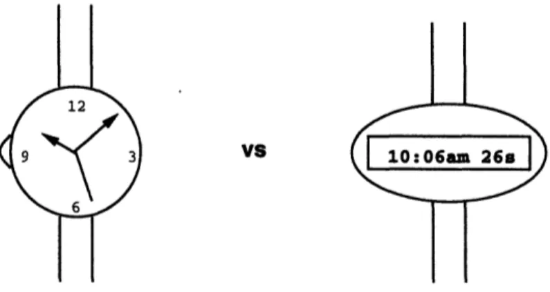
allow users to view events as sequences of text data. Newer systems like DPD have shifted event visualization to a graphical basis[15]. Based on experience with existing debuggers, text is useful for showing the specific value of data associated with any given state during run-time, but graphical display is better suited for showing the dynamic movement of data as the state of the program progresses. For example, consider a source-level debugger. In such a tool, it is appropriate to show the values that variables hold in text form. Trying to convey the value of an integer variable via a bar graph is difficult when the range is large. On the other hand, it makes sense to display how he variable has changed over time in a graphical format. A line graph which maps the values over time is more useful than a spreadsheet listing the values and the times at which they happened. Figure 3-1 shows two different scenarios - the
VS
A Case for Textual Display
Os 2s 5s 7s lOs 12s 15s 17s 20s 22s 25s 27s 30s 32s 35s 37s 40s 502mph 1000mph 512mph 549mph 525mph 516mph 750mph 617mph 749mph VS 779mph 883mph 500mph 912mph 735mph 710mph 690mph 250mph 500mph 493mph 480mph 476mph 0 1 nla 2n 3ns ANq Time
A Case for Graphical Display
Figure 3-1: Graphical vs. Textual Display
first an argument for textual display and the second an argument for graphical dis-play. Based on the philosophy that both graphical and textual display are useful for different classes of visualizations, Creatr should display event-flow graphically while event content should be text based.
3.1.5 Customization
Past debuggers have been very limited in their scope of customization. While Peter Bates' system allows users to define higher level events based on lower ones, during presentation time users cannot selectively filter event content. The same holds for
other existing debuggers. Likewise, most graphical system-level debuggers hardcode the way in which they display event-flow. This limits the usefulness of the graphical
display.
To encourage use, Creatr should export three levels of user-defined customizations. First, users must be allowed to customize the graphical presentation of event-flow. Second, users should be able to filter events and selectively display only the interesting ones. Finally, the textual presentation of event data needs to be user-defined.
3.2
Overview
The design of event driven, system-level debuggers can generally be broken down into three parts: a back-end, an engine, and a front-end. The back-end is responsible for communicating with the target software. This means receiving event packets from
the target and, for interactive debuggers, injecting synthesized events back into the
target. The engine acts as a mapping agent and database for the events. It maps the incoming events into a format consistent with the system model, and then stores the events in an internal database. The engine also services database queries. Some engines are passive - they pass data to the client only when queried. Others are active - information is passed upon availability. Finally, the front-end displays the
system-level view of the target environment to the user. Information about the target
environment is queried from the engine.
The back-end/engine/front-end model can also be thought of as a client-server system. The back-end services the engine by collecting primitive events from the
target and passing them to the engine. The engine provides the front-end with a
high-level view of the target. Finally, the front-end services the user by visualizing the system-level view of the target execution.
In past debuggers, all three sections have been strictly defined. Back-ends received predefined events, engines stored them, and front-ends displayed them.
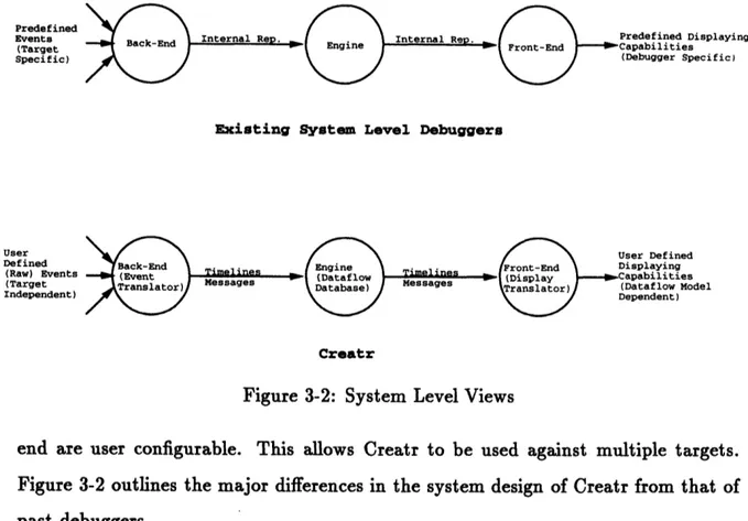
Creatr uses a similar approach with two major differences. First, the engine models a less restrictive environment. Second, both the back-end and the
front-Predefined Events (Target Specific) Predefined Displaying -Capabilities (Debugger Specific)
Existing System Level Debuggers
User Defined (Raw) Events (Target Independent) Creatr
Figure 3-2: System Level Views
end are user configurable. This allows Creatr to be used against multiple targets. Figure 3-2 outlines the major differences in the system design of Creatr from that of past debuggers.
3.2.1
EventFlow Modeling
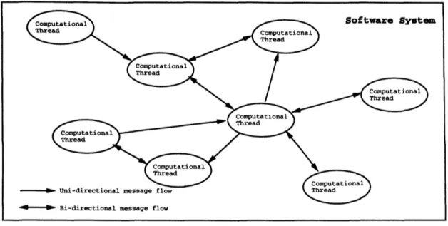
Creatr's engine is based on the EventFlow model. EventFlow is used to model high-level systems in which separate, loosely coupled execution threads have different tasks. System integration is accomplished through message passing. An abstract view of such an environment is shown in Figure 3-3. In this figure, each thread is just some piece of software responsible for a specific subtask. Through communications, the subtasks are combined to build a larger system.
The EventFlow model was chosen as the appropriate model for Creatr's engine because it represents a more flexible model than previous debuggers have used. In fact, some of the models used previously can be viewed as subsets of the more gen-eral EventFlow model. In particular, the distributed programming model can be interpreted as a EventFlow model in which the computing entities are the separate processes and the event-flow is the IPC. However, other programs, which may not
*--) Bi-directional message flow
Figure 3-3: The EventFlow Model
be considered distributed at the process level, can still be modeled using EventFlow. Single process, multi-threaded systems are EventFlow based. Threads are objects and shared memory allows for inter-thread communications. Even sequential pro-grams use the EventFlow construct. Object-based propro-grams have data objects which are responsible for accomplishing a subset of the total work. Multiple data objects
communicate with each other through exported methods. EventFlow could probably
be used to model just about any software system. Arguably, even at the object-level, each instruction represents a separate object. Data is passed from instruction
to instruction using registers and memory. However, the lower the granularity of
the objects, the harder it will be to accurately model the system using EventFlow.
EventFlow is intended to model systems in which the object granularity desired is significantly higher than source-level.
Event Driven Debugging and Terminology
As mentioned earlier, debuggers are event driven systems. Events occurring in the target environment signal actions to the debugger. Creatr is based on this design. Because Creatr models EventFlow, each target event must have some mapping into the EventFlow model.
Creatr internally models the EventFlow environment using two constructs: time-lines and messages. Timetime-lines represent computing objects while messages represent the event-flow items. Computational entities do not need to exist throughout the lifetime of a system. Often, one object will spawn another. When an assigned task is completed, objects may disappear. To model this behavior, timelines are dynamic. They have a starting time and an ending time. Messages are actions occurring at
a specific time. They are commonly associated with timelines since the event-flow happens among objects.
Target events are used to signal timeline and message actions. There are three different classes of events, two for timelines and one for messages. Timeline-events include creation-events and destruction-events. A creation-event signals the creation of a new timeline. Destruction-events signal the destruction of existing timelines. Message-events are used to notify Creatr that a new message should be added to the current modeling environment.
Finally, EventFlow modeling is time-sequenced. When a model is first created, there are no timelines or messages and the model's logical clock is initialized. Every
time a target event occurs, an appropriate action is taken by Creatr. The action
is timestamped with the current time, and the time incremented. Thus, there is
a causality relationship between all events in the EventFlow environment. Messages have an ordering in the time-space based on when a message-event occurred in relation to other message-events. Timelines have a limited lifespan. Their start and end times are determined by creation and destruction-events respectively.
3.2.2
Customization Facilities
Creatr's back-end and front-end are user configurable. This is accomplished by provid-ing the user with lprovid-inguistic support for customization. The user defines the customiza-tions in various configuration files. Creatr then uses these definicustomiza-tions to interface to
a target and to provide a graphical front-end to the user.
As mentioned earlier, Creatr is designed with ease of reuse in mind. Use of con-figuration files for customization lets users ignore implementation details internal to
the tool. Furthermore, once the configuration files are specified, building a completed Creatr is transparent. Creatr uses an interpreted environment for the linguistic sup-port it provides. Instead of specifying a configuration, compiling some object based on the definition, and then linking that against Creatr's core to build a final executable, Creatr is already an executable with built-in interpreters.
Back-end
The back-end of Creatr is customizable. Users can provide event definitions. Using a language outlined in a later section, users specify the events that will be happening in the target environment and how they map to Creatr's notion of EventFlow. Based on the definitions, users need to add hooks to the target sources. These hooks are the run-time mechanism through which Creatr is notified of target events.
The main power of this approach is that Creatr becomes a generic debugger which can be used across multiple targets, each of which may have a separate notion of events. While users must add target-side hooks explicitly, they do not need to be aware of how Creatr deals with the hooks internally. Ideally, Creatr should provide an automated way of inserting hooks into a target (much like source-level debuggers embed symbolic information into code during compile time). Unfortunately, in the context of system-level debugging, this is a hard problem and thus has not been attempted. However, to reduce the interfacing costs, the back-end encapsulates the packet level protocol used to deliver events.
Front-end
Creatr's front-end lets users define exactly how they want to display things graphi-cally and textually. Graphical presentation is used for event-flow visualization while
textual presentation is used for event content visualization. Three customization
facil-ities are provided: two for event-flow visualization and one for content visualization. Like event definitions in the back-end, these facilities are language driven and the
configuration files interpreted at Creatr run-time.
can hardcode a mapping from events to graphics. Before an event is visualized, the tool does a table lookup to see how the event should be displayed and then renders accordingly. Creatr's back-end allows users to define primitive events. A mapping from events to graphics cannot be easily embedded within Creatr when the events may be redefined across applications. In Creatr, users can define infinitely many different event types. Hardcoding rendering routines for some subset of these event types would probably not be useful. Furthermore, each event could be rendered in infinitely many ways. Some users may find one style useful while others may feel differently. Instead, Creatr lets the user define the graphical rendering of events. Rendering is accomplished by writing routines for each back-end event type in a visualization language.
Past experience suggests that filtering capabilities are useful because large systems have high event-flow traffic. If the user wants to debug a specific module within
the target, he/she is probably not interested in seeing unrelated event-flow. Creatr
exports a filtering language which can be used to filter events based on event type
and content.
After events have been collected from a target, the user may be interested in viewing the content of specific events. However, event data coming from a target environment will be in binary form. From a debugging standpoint, binary data is not as useful as symbolic representations. Creatr has a data formatting facility through which users can specify symbolic mappings for data. During the textual display of
event data, instead of displaying bit patterns, Creatr will match the bit pattern to
a string based representation based on the configuration specified. This string is
Chapter 4
Design
The latter portion of the previous chapter gave a brief overview of Creatr from a conceptual viewpoint. This chapter details the complete design of a toolkit based
on the ideas presented. It begins by presenting an overview of the toolkit itself and
then details each specific module. Design issues concerning the user interface are discussed, as is the linguistic support the back-end and the customization facilities provide. Based on the design presented in this chapter, the reader should be able to implement a system-level debugger which incorporates the ideas Creatr presents.
4.1
High-Level View
Creatr is a system-level debugger which allows users to view events in a target pro-gram. To do so requires some form of run-time interaction between the target and
Creatr. Creatr must be notified of events that are happening within the target so that
it can display the information to the user. To accomplish this, Creatr is designed as a set of tools. The first pair of tools, CTRHDR and CTRLIB, are coupled to the tar-get program. They act as the hooking mechanism within the tartar-get software, which delivers events to the other tool, CTRVIEW. CTRVIEW is the visualization tool. It receives events from the target, maps them to a EventFlow model, and based on user customizations, displays them. Figure 4-1 presents a system-level view of the toolkit set and shows how each of the parts interacts with a target.
(target executable)
I...I
CTRVZOW
(executable)
Run-Time Environment
As mentioned in the last chapter, Creatr is composed of three modules: the back-end, the engine, and the front-end. While the engine and front-end are embodied only in the visualization tool, the back-end's functionality is divided among all three tools. The remainder of this chapter describes in detail the functionality of each of
the three modules.
4.2
Back-End
The back-end of Creatr is responsible for maintaining the run-time interaction with the target application. It receives raw, user-defined events from an application, maps them into timelines and messages accordingly, and then delivers the synthesized time-lines and messages to the engine. The back-end is customizable. Users can specify the mapping of raw events to timelines and messages.
4.2.1
Event Mappings
To describe a mapping of target events to Creatr timelines and messages, two pieces of information are needed. First, the user needs to decide what each event signals. Does the event signal a message or the creation/destruction of a timeline? The second piece of information is the content of the raw event. Useful events contain a timestamp (when did the event happen), and some information (where did the event
happen and what was the surrounding context). The former is handled internally by Creatr. Creatr time sequences all generated events. The latter is accomplished by
users defining the makeup of an event.
An Event Definition Language (EDL) represents the means through which users can define event mappings. Users write event definitions in EDL, which are then used
by Creatr to negotiate the run-time communication between Creatr and the target.
The definitions are also to build an EventFlow model from the generated events.
The EventFlow model is composed of objects and the interactions among them. As mentioned in the previous chapter, Creatr models the objects and flow using
These events, when received by Creatr, will need to be mapped to either timelines or messages. In EDL, users define the complete set of raw events which could be generated during target execution. Users also specify what each event signals: mes-sage, timeline creation, or timeline destruction. Finally, they specify the information that accompanies an event. While event to timeline/message mappings are important because they provide the mechanism through which target systems can be modeled using EventFlow, the actual composition of an event is vital because it dictates much of the visualization scheme.
One important aspect of message-events is that they are most likely linked to various timelines in some manner. For example, in a distributed environment, IPC messages are associated with two timelines: the sending process and the receiving process. When viewing a message-event, it is common to need information about the timeline-event. EDL provides linguistic support for naming timeline-events and referring to such events from message-events. This way, message-events only need to have pointers to timeline events. As discussed later, this also proves useful for the visualization semantics.
Finally, while EDL is mainly for defining event structures, it also allows users to define static events. This is useful for persistent timelines. For example, in a distributed environment, multiple processes may be communicating with each other. A subset of these processes may always exist, while others are spawned and killed. For processes that are static, run-time communication overheads can be reduced by defining static timeline-events for each such process. Furthermore, this reduces costs associated with interfacing Creatr to new targets. Users do not need to add hooks for persistent events in the target sources. The next section describes in more detail how Creatr and a target interact and should help make clear why static events are useful.
4.2.2
Event Delivery
At run-time, Creatr needs to be informed of the events which a target application will be generating events. A communication link between Creatr and the target needs
to exist. The sending end of this link must be embedded within the target, and the receiving end within Creatr's visualization tool. To accomplish this, the back-end is distributed across all three tools. CTRHDR and CTRLIB embody the sending end and the receiving end is contained in CTRVIEW.
CTRLIB is an injection library. User can use this library to add event creation
hooks to target software. Within the target sources, the user needs to decide when it
is appropriate to create an event. Based on the event definitions the user provides, routines provided by the library allows users to build and transparently deliver raw events to the receiving end. This is useful because it provides a single entry point from the target to Creatr and also encapsulates the packet level protocol used to deliver events. As a result, the user need not know the protocol. It also reduces the total amount of extra code a user needs to add to the target sources when interfacing
it to Creatr.
CTRHDR is a secondary tool which provides information concerning event defi-nitions to CTRLIB. The sending end of Creatr needs to know the composition of raw events, but not how they map to timelines and messages. When the user makes calls
to the library routines, the routines can internally parse the event definition file to
get this information. Based on the composition, the library then needs to define a packet protocol which can be used to send the event from the target to the visualiza-tion tool. To reduce performance overheads, this funcvisualiza-tionality is pushed out of the
run-time environment. Instead, CTRHDR parses the event definitions and generates
a header file which defines the packet protocol for each event type. This header is then used by CTRLIB to build packets from events and deliver the packets.
To realize the packet-level protocol, the back-end of CTRVIEW also parses the event definition. When packets are received from the target, CTRVIEW can appro-priately rebuild the raw event, map them to timelines or messages, and deliver them to the engine. The reason CTRVIEW directly parses the event definitions instead of using another tool like CTRHDR is because such a scenario would require recompil-ing CTRVIEW each time the definitions changed. As mentioned earlier, to reduce migration costs, the user should never have to rebuild the Creatr system.
4.2.3
Time Sequencing of Events
As mentioned in Chapter 3, all collected events are time-sequenced and ordered. However, the issue of correct ordering was not addressed. In distributed environments, multiple processes can be generating events. If process A generates a message-event before process B, will Creatr receive and order the two events correctly? Do the two events even need to be ordered correctly? Creatr is designed to display events using a total ordering scheme. Each event is assigned its own timeslot in an internal, global timespace. The ordering is determined by the order in which events are received. Thus, Creatr needs a communications substrate which guarantees that events are received by Creatr in the same order that they are generated in the target.
Currently, Creatr ignores this issue. The assumption is made that a reliable, totally ordered multicast mechanism exists. This communication system should en-forces an ordering based on a global target clock[10]. The total ordering is time based. If event A occurred at a logical time prior to event B, then A "happened-before" event B. In other words, Creatr does not support event concurrency within the target. There is a one-to-one mapping between events and timeslots.
In reality, ordered multicast systems may not exist for various platforms. The current implementation of Creatr uses a FIFO piping mechanism. Pipes are one-to-one communication protocols. Thus, while Creatr can guarantee correct ordering for sequential targets, it does not currently support ordering across a distributed
target. Future versions of Creatr should incorporate the communications layer into
its design. Totally ordered multicast protocols have already been developed and do not need to be redesigned. Examples include the ISIS ABCAST primitive[4] and the xAMp system[13].
Creatr is designed to display a total ordering among events in the target envi-ronment. However, it may not be necessary to define a total, time-based ordering on all the generated events in a distributed environment. The user may feel that a partial ordering is sufficient. Since each event is given its own timeslot, Creatr is then free to derive a total ordering based on the partial ordering. User-defined par-tial orderings are needed in this case. One possibility could be to somehow extend
EDL to allow users to not only define event types, but also define causal relations between the events. A mechanism would also be needed to define a target "process". Then, Creatr can keep a separate clock for each "process" and use the causal rela-tions to determine ordering among events generated during the same logical time. Partial ordering schemes which could help implement such a feature already exist. The Psync protocol implements a partial ordering scheme by assigning precedence to operations[12]. This protocol could be adapted to work within a modified Creatr. Precedence would be established across events instead of operations.
4.3 Engine
The engine represents the section of Creatr that is not involved in target interfacing. Engine functionality cannot be customized by the user. The back-end receives user-defined events from the target environment and maps them to timelines and messages. The front-end is used to customize the graphical and textual display of the different timeline and message types. The engine acts as the glue for the interfacing layers. It stores synthesized timelines and messages and also manages the user interface through which the front-end customizations are rendered. Both the back-end and front-end are language driven. Their main tasks are to parse configuration files and interpret them when appropriate. The engine drives the entire process by acting as
the I/O mechanism for the end-user. Users tell the engine what history they want
to view. The engine then displays all events in the requested history for the user. If customizations for certain events are specified in the front-end, the engine will make
calls to the front-end. The front-end interprets the specified display routines, making
appropriate calls back into the engine when output to the user is desired.
Creatr's engine is contained within the visualization tool, CTRVIEW, and is com-posed of two parts: the object database and the graphical user interface (GUI). The object database handles receiving timelines and messages from the back-end and stor-ing them internally in a manner consistent with the EventFlow model. It also services requests to access the timelines/messages and their associated primitive events. The
GUI is the physical user interface to Creatr. It handles requests from the user dealing with the collection and viewing of events from a target. Often, GUIs are considered front-end modules. In Creatr, the GUI is part of the engine. This decision allows the core functionality to remain separate from the user-defined functionality. However, the GUI and the front-end are closely related. The GUI presents a standard system-level view of the target to the user. It is also used to render any customizations the user has specified in the front-end.
4.3.1 Object Database
The object database enforces the EventFlow model by collecting timelines and mes-sages and storing them internally as histories. It also services requests by the GUI and front-end customization facilities to retrieve information about histories and the timelines/messages in them. Finally, the object database also acts as the manager for the GUI. It keeps track of open windows, the histories being displayed in various windows, etc.
Creatr supports real-time event collection and viewing through the object database.
Histories do not need to be completed to have requests for them serviced. If an open history is requested for viewing, the object database will deliver all existing timeline and messages. The database keeps tabs on which window is requesting which history. If more events arrive for a history which is opened for viewing, the database will deliver them to the window as they are received.
To achieve the functionality described above, the object database is both passive and active. It passively receives target events from the back-end as the events are triggered. The interaction with the front-end and GUI is passive and active. A passive request to open a history causes the database to switch into an active role. It delivers all events currently in the opened history to the client. As more events are received
from the back-end, they are automatically delivered to the requesting client. This
4.3.2
Graphical User Interface
The GUI is the physical user interface. It is a window-based, menu-driven front-end to Creatr. It handles requests from the user concerning the collection and viewing of target events. The GUI is the portion of Creatr that users interact with during debug time.
The GUI is designed with user needs in mind. Based on experience, system-level debugging involves collecting many histories from various runs of a target and then comparing the histories for discrepancies, differences, etc. The GUI allows users to see many histories concurrently. It also lets users control the collection of timelines and messages into different histories. Because debugging is a time-intensive process, the GUI also lets users save and retrieve histories to persistent memory. The main job of the GUI is to allow users to view various collections of timelines and messages. To do so, it depends on user-defined customizations. Every time a timeline or message is to be rendered, the GUI calls the appropriate front-end routines. The GUI also provides services to the front-end routines. To actually render anything to the screen, during
interpretation time, the front-end will make calls to user interface routines provided
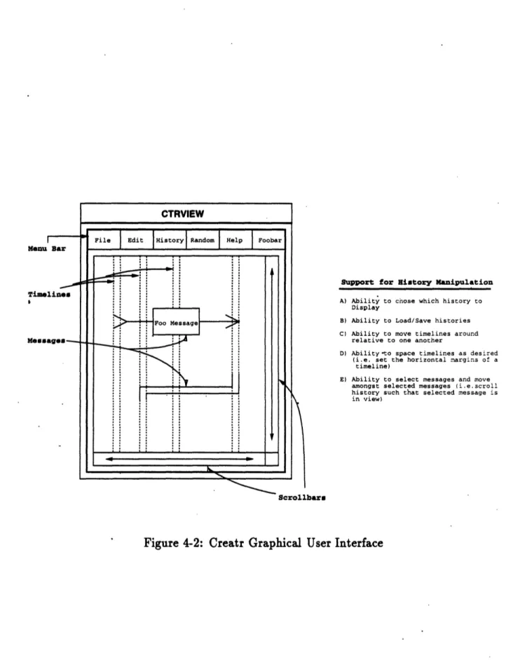
by the GUI. While event-level customizations are provided by the front-end, the GUI provides direct support for history-level customizations. Figure 4-2 presents a rough sketch of Creatr's GUI and also outlines some of the support it provides for manipulating histories.
4.4 Front-End
Creatr's front-end lets users customize the display of timelines and messages and is part of CTRVIEW only. As mentioned Chapter 3, it is useful to have both graphical and textual display. The graphical display should allow users to get a system-level view of the target flow while the textual display should provide for event-level vi-sualization. reatr graphically displays histories, a coherent set of timelines and
messages. On the other hand, event data is textually presented to the user.
Support for History Manipulation
A) Ability to chose which history to Display
B) Ability to Load/Save histories C) Ability to move timelines around
relative to one another
D) Ability-to space timelines as desired (i.e. set the horizontal argins of a
timeline)
E) Ability to select messages and move amongst selected messages (i.e.scroll history such that selected message is in view)
Scrollbars
and one for the textual display. Graphical visualization is used to define how timelines and messages get graphically drawn while filtering allows users to specify which subset of the timelines and messages are of interest. Message formatting is used to define how raw data within message-events gets mapped to symbolic strings.
4.4.1
Visualization
The visualization facility controls the graphical presentation of timelines and mes-sages. When the user requests to view a history, the GUI will retrieve the appropriate history from the object database. Graphical display of the timelines and messages within the history are then based on the customizations provided by the user.
Graphical visualization in Creatr is based on the event definitions from the back-end. In a language called VL (visualization language), users define how each of the EDL based events will be drawn. During graphical display, Creatr will iterate through all the events, and in the process, call each event's drawing routine.
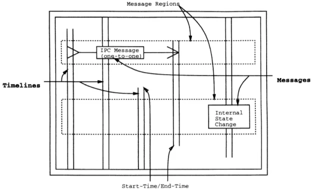
Events in Creatr can map to either timelines or messages. The general presentation of timelines and messages is outlined in Figure 4-3. Timelines are vertically running pairs of lines which have a defined start time and a defined end time. Sequencing of start and end times are determined by the events signalling creation and destruction respectively. Messages are vertically stacked rectangular regions. Events in Creatr are time sequenced based on when they are received. If message A is located above message B, then the event which triggered message A was received by Creatr prior to the event which triggered message B.
VL allows users to customize the drawing of the EDL-based events. Because events can map to either timelines or messages, VL provides different customizations for each event type. Timeline visualizations are limited while message visualizations are open-ended.
While timeline visualization is largely predefined, VL does allow the user some flexibility. Users can chose the draw pattern used for the outline and the interior of a timeline. The outline and interior can also be dynamically changed based on the messages associated with an event. This is useful for showing internal object state
Message Region
.,
le-to-one .. . .. . .. . . IPC Message] . ... ...I
Internal State Change ... ... . ... .... I II Messages Start-Time/End-TimeFigure 4-3: Basic Timeline and Message Visualization
changes of within the target. For example, in a distributed environment, processes can be active or asleep. Message events have been defined to signal wake-up and sleep. Furthermore, the user would like to view an active timeline as two solid lines and a sleeping timeline as two dotted lines. At run-time, the drawing state of the process timelines can be toggled based on the message-events received. Sleep events cause the timeline to start being drawn dotted and wake-up events cause it to be drawn as solid lines. This functionality allows users to graphically view the execution state of objects without having to manually view each event which signals a state change.
Message visualization is very flexible and draws much of its power from the fact that message events are likely to be bound to timelines. During viewing, each message is assigned a timeslot based on the order in which Creatr received the message event. To draw messages, Creatr will sequence through all the messages. Beginning with the message assigned the lowest timeslot, Creatr will call each events drawing routine. When a routine is called, it gains control of the entire viewing screen. The routine can then draw the message how and where it chooses to. To support message drawing,
Timelines . I I -l I- I
I.
. .. . . Fo... 1' -- - - ...o _ v ... o . ... ... >-· --- ... I--- -- -'I
----I. I ---. ... . ... o. ' -I IVL provides primitive drawing capabilities. Primitives for line, square, circle, and text drawing are all supported. Furthermore, VL gives the user the ability to change the state of the drawing brush. This include the brush style, brush width, fill pattern, and foreground/background colors.
While users can draw each message anywhere on the viewing screen, in general, there should be some ordering. Since time-space progresses downward, messages which occur after other messages should be drawn below the previous messages. Dis-play ordering is accomplished through vertical offsets. Each routine specifies how much vertical space it uses to render a given message and all drawing primitives ac-cept relative y coordinates. The absolute y coordinate is derived by adding in the vertical space reserved for all prior messages. If users draw only within the reserved y space and never specify negative y coordinates, then each message will be rendered in the correct order with no overlapping.
In addition to the drawing support outlined above, VL provides extensions to EDL-based events. These extensions can be useful in rendering messages. First, the horizontal positioning of timelines is exported through timeline-event extensions. Messages can reference associated timelines. A timeline can reference its horizon-tal position. Thus, a message can horizonhorizon-tally position itself through its timelines. Second, the filter state of each event can be referenced. Messages containing filtered timelines are not automatically filtered. By referencing a timeline's filter state, a mes-sage can dynamically change the way it should be rendered when certain associated timelines are hidden. Finally, message-events have a selection field. While Creatr's GUI allows users to select/deselect messages, no general display capability is pro-vided through which users can distinguish selected and unselected messages. User's can improvise by making message visualization a function of the selection state.
4.4.2 Filtering
Creatr provides a filter through which users can hide uninteresting events. Large target systems may have a variety of event definitions and multiple injection points. During run-time, Creatr could be collecting a huge number or events from the target.
However, the user may not want to view all the events. More often, the user will be debugging a subset of the entire target and wants to see events related to that section of the target only. By setting up a filter, users can hide unrelated timelines and messages. As mentioned above, after a GUI retrieves a history, it iterates through all the events, calling their drawing routines. Before a drawing routine is actually called, the event is processed by the filter. If the event passes through the filter, then the drawing is done. Otherwise, the event is simply skipped and not displayed to the user.
Filters are written in FL (filtering language). FL provides support for filtering based on event type and content. For each event type, users write a filter routine. Linguistic support for regular expression matching is used to filter based on event
data. Users can specify a regular expression which some portion of the event data is matched against. Based on the success of the match, the event is passed through the filter and drawn, or caught and skipped. Language support for timeline-events and message-events is identical. While message-events directly map to messages, timelines have one or two events associated with them: creation and destruction events. Timeline filtering is based on the creation event. Events signaling timeline
creation are filtered to determine if a timeline should be drawn. Destruction events are simply ignored during filtering.
One interesting aspect of the filter is that messages which contain hidden timelines
are not automatically filtered. Situations may arise in which users want to render
messages even when related timelines are hidden. To avoid compromising such func-tionality, no implicit filtering is performed. Rather, FL provides an event extension through which the user can access the filter state of an event (similar to the filter state extension provided by VL). Users can then explicitly filter a message based on the filter state of associated timelines.
The other important feature deals with timeslot allocation and ordering. All events have a distinct ordering. However, filtered messages lose their reserved space allocation in the view screen. This collapses the user-viewable time-scale when there are hidden messages. For example, suppose there are three messages, A, B, and C,
each having a vertical space reservation of 25 units. If nothing is filtered, the three messages will consume 75 units of vertical space in the view screen. However, if message B is filtered, only 50 units will be consumed by messages A and C. Message C will be rendered in the space directly below message A. No space is reserved to show that there is really a message between the two which happens to be filtered. The same is true for timelines. A timeline has a creation-event and possibly a destruction-event. If between the two events, there are five message-events and nothing is filtered, then the user will perceive the timeline to have existed through five timeslots. However, if any of the intermediate messages are filtered, then the user's perception of a timeline's
lifespan is skewed as well.
4.4.3
Message Formatting
In the same manner that the visualizer and filter customize the graphical presentation
of timelines and messages, the message formatter lets users customize the textual presentation of message-based event data. To view the content of message events, users select the graphical message. This causes a separate window to appear which contains the event data. However, event data is in binary form. Users like symbolic representations. Furthermore, it may be useful to process the event data and display a report accordingly. To support this functionality, each message-event is sent through the message formatter before having its data displayed. Instead of displaying the
event data, the report generated by the message formatter is displayed.
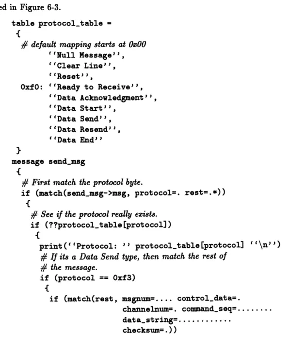
The language used to write message formatters is MFL (message formatting lan-guage). MFL is similar in functionality to the FL. Separate routines are written for each event type (message-events only), and regular expression matching controls re-port generation. Primitives for rere-port generation also exist and are like the "printf" routine in C.
MFL does not support state. In other words, the action performed on each message-event is only dependent on that event. This is a clear deficiency in the lan-guage and future versions of MFL should probably include such functionality. Static global variable support is an example of one simple approach.