Control of Size and Charge Selectivity in Amphiphilic
Graft Copolymer Nanofiltration Membranes
by
Nathan Gary Lovell
B.S. Chemistry, University of Utah, 2001 B.C.S. Computer Science, University of Utah, 2002
S.M. Materials Science and Engineering, Massachusetts Institute of Technology, 2005
Submitted to the Department of Materials Science and Engineering in Partial Fulfillment of the Requirements for the Degree of
Doctor of Philosophy in Materials Science and Engineering at the
Massachusetts Institute of Technology September 2010
©2010 Massachusetts Institute of Technology All Rights Reserved
Signature of Author:_________________________________________________________ Department of Materials Science and Engineering
June 28, 2010 Certified by:________________________________________________________________
Anne M. Mayes Toyota Professor of Materials Science and Engineering Thesis Co-Advisor Certified by:________________________________________________________________
Michael F. Rubner TDK Professor of Materials Science and Engineering Thesis Co-Advisor Accepted by:_______________________________________________________________
Christopher Schuh Danae and Vasilios Salapatas Associate Professor of Metallurgy Chair, Departmental Committee on Graduate Students
Control of Size and Charge Selectivity in Amphiphilic
Graft Copolymer Nanofiltration Membranes
by
Nathan Gary Lovell
Abstract
The throughput and efficiency of membrane separations make polymer filtration membranes an important resource for the pharmaceutical, food and wastewater treatment industries. Nanofiltration (NF) membranes fill an important niche between nonporous reverse osmosis membranes, which have comprehensive solute rejection and low solvent permeability, and porous sieving ultrafiltration membranes. However, challenges in NF membrane design remain outstanding. At the effective pore size of NF membranes (~0.5 nm-2 nm), both electrostatic and steric factors determine membrane selectivity. Most NF membranes are charged under a wide range of environmental conditions and thus preferentially exclude charged solutes. This charge selectivity precludes separation of molecules based solely on size. An additional limitation of NF membranes is the tendency to foul by adsorption of feed components. The purpose of this thesis is to demonstrate control of membrane selectivity in fouling resistant membranes via manipulation of the chemistry of a specific copolymer system, polyacrylonitrile (PAN)-based poly(ethylene oxide) (PEO) graft polymers.
Previous work with amphiphilic graft copolymers as membrane materials has included
PAN-g-PEO with an average graft length of 9 (PAN-PAN-g-PEO9). PAN-PAN-g-PEO9 was shown to have
excellent fouling resistance as an antifouling additive in porous ultrafiltration membranes and as a dense selective layer coated onto a support base membrane—a thin-film composite (TFC) NF membrane. The comb morphology of the polymer imposes high interfacial area on the microphase-separated domains, resulting in a bicontinuous structure consisting of a glassy PAN matrix interpenetrated by PEO-filled "nanochannels" that can act as vias for water and small solutes (with a size cutoff of ~0.8 nm). It also presents a PEO brush on the comb surface which acts as a steric barrier to resist irreversible fouling of the membranes. The understanding from previous work on PEO comb NF membranes is that the pore size is determined by the nanochannel’s size, i.e. the PEO domain size.
Because the graft characteristics (spacing and length) of comb copolymers determine the domain size, it was expected that varying the graft length would allow broad, precise control of the size cutoff of the TFC membranes, a concept demonstrated previously with amphiphilic graft copolymer NF membranes of poly(vinylidene fluoride)-graft-poly(oxyethylene methacrylate) (PVDF-g-POEM). The first aim of this thesis was to tailor the retention properties of PAN-g-PEO TFC NF membranes by modifying the chemistry to tune the electrostatic and steric properties sufficiently to enable complex separations, particularly of solutes with high fouling potential. Comb copolymers incorporating ~40 weight % PEO with side chains varying from 5-40 EO units were synthesized by free radical methods and compared as selective-layer coatings on PAN UF membranes.
Membranes incorporating combs with 9 EO units or more were shown to resist irreversible fouling when challenged by a model protein feed solution (bovine serum albumin) for 24 hours. Fouling resistance was found to be compromised, however, upon exposure to acid (pH 2) solution, used to simulate chemical cleaning procedures in industry. Thickness-normalized permeabilities of these PAN-g-PEOn NF membranes exceeded those of commercially available NF membranes by approximately an order of magnitude. A systematic effect of side chain length on permeability was seen when varying temperature, ionic strength, and pressure. Contrary to expectations, the membrane size cutoff (~0.8 nm) for charged rigid molecular probes in deionized water was independent of the comb side chain length. This new finding can be explained by modeling the hydrophilic domains as opposing swollen polymer brushes of uniform density acting as a physical gel. The gel mesh size (distance between chains) is independent of side chain length, and controls the size cutoff in good solvent conditions matching those in which the membrane was equilibrated during fabrication. In poorer solvent conditions, a decrease in the brush height, progressing to complete collapse of the PEO gel, can be expected to create differentiation based on domain size (i.e. side chain length). This is consistent with the finding that retentions of dyes increased with decreasing side chain length in saline solution, as salt is known to reduce PEO-water miscibility.
Fluorescently labeled peptides germane to proteomics research were filtered and both chromatographic and size-selective membrane behavior was observed—the first demonstration of size-based nanofiltration of peptides. Based on this finding, two different peptides of molecular weights 1.3kDa and 1.5kDa were fractionated to achieve a six-fold increase in the concentration of the larger peptide relative to the smaller peptide in two filtration steps.
The electrostatic selectivity of the PEO comb membranes could also be varied. Terpolymers consisting of PAN-g-PEO with 1-2% charged sulfopropyl acrylate (SPA) or 5% N,N-dimethyl-N-(2-methacryloyloxyethyl-N-(3-sulfopropyl) ammonium betaine (SPE) were synthesized and coated onto PAN base membrane. The divalent salt (Na2SO4) retention of the resulting TFC membranes increased from ~20% for the PAN-g-PEO copolymer to ~45% and 82% for the SPE and SPA terpolymers, respectively. Retention of monovalent NaCl was substantially lower, characteristic of commercial NF membranes. The charged comb membranes did not completely resist fouling by a 1 g/L BSA solution, losing 2% of the initial flux after 24 h exposure. Forming a trilayer TFC, with a layer of PAN-g-PEO coated over a charged terpolymer, reduced membrane fouling compared to the charged layer alone.
In summary, the goal of this study was to demonstrate control of membrane selectivity in fouling-resistant PAN-g-PEO NF membranes. An important finding was that the PEO gel created in the hydrophilic domains leads to similar size cutoffs over a wide range of side chain length. To access the desired spectrum of size cutoffs, the quality of solvent for the swollen PEO brush must be reduced. In spite of these limitations, the membrane was shown to have useful fractionating properties as demonstrated with labeled peptides of varying molecular weight. The retention of salts was enhanced by incorporating small amounts of charged monomer into the comb backbone, but at the expense of fouling resistance.
Table of Contents
Abstract . . . 2 Table of Contents . . . .4 List of Figures . . . .8 List of Tables . . . .10 Acknowledgements . . . 11 1. Overview . . . 12 1.1. Introduction . . . .121.2. Water and Sustainability . . . 13
1.3. Water Purification and Membranes . . . .13
1.4. Membranes . . . 15
1.5. Metrics of Membrane Performance . . . .16
1.6. Membrane and Membrane Process Limitations . . . 17
1.6.1. Concentration Polarization . . . 17
1.6.2. Fouling . . . .17
1.6.3. Fouling and Selectivity . . . 18
1.6.4. Selectivity . . . 19
1.7. Improving Membranes . . . 19
1.7.1. Fouling Resistance . . . .19
1.7.2. Controlled and Uniform Pore Size . . . 21
1.8. Amphiphilic Graft Copolymer Nanofiltration Membranes . . . .22
1.9. Outline . . . .24
2. Experimental Methods . . . 26
2.1. Introduction . . . .26
2.1.1. Material Synthesis Considerations . . . 26
2.1.2. Membrane Fabrication Considerations . . . 27
2.1.3. Applications . . . .27
2.2. Materials . . . 28
2.2.1. Monomers, Reagents and Polymeric Casting Additives . . . 28
2.2.2. Membrane Characterization Probes . . . .29
2.2.3. Membranes . . . 29
2.3.1. Synthesis of Polyacrylonitrile-graft-poly(ethylene oxide) . . . 30
2.3.2. Chemical Characterization . . . .31
2.3.3. Physical Characterization . . . .32
2.4. Synthesis and Characterization of Comb Terpolymers . . . .32
2.4.1. Synthesis . . . .32
2.4.2. Terpolymer Characterization . . . .33
2.5. Membrane Coating . . . 34
2.5.1. Coating Method . . . .34
2.5.2. Coating Thickness and Contact Angle . . . 35
2.6. Atomic Force Microscopy Colloidal Probe Measurements . . . 36
2.7. Membrane Bacterial Adhesion . . . 36
2.8. Membrane Filtration Experiments . . . .37
2.8.1. Permeability . . . .37
2.8.2. Fouling . . . .38
2.8.3. Molecular Probe Retention . . . 38
2.8.4. Peptide Retention . . . .40
2.8.5. Nanoparticle Retention . . . 41
2.8.6. Salt Retention . . . 41
2.9. Membrane pH Stability . . . .42
2.10. Summary . . . 42
3. Fouling-resistant Nanofiltration Membranes with Controlled Size Cutoff . . . .43
3.1. Introduction . . . 43
3.2. PAN-g-PEO Combs with Varied Side Chain Lengths . . . 44
3.3. Thin-Film Composite Nanofiltration Membranes: PAN-g-PEO Coatings on PAN Base Membrane . . . 46
3.3.1. SEM Micrographs of Membranes . . . .46
3.3.2. Contact Angle . . . 48
3.4. Membrane Fouling Resistance . . . 49
3.4.1. AFM Force Measurements: Carboxylate-Modified Particle Adhesion . . . .49
3.4.2. Bacterial Adhesion . . . 50
3.4.3. 24 Hour Bovine Serum Albumin Filtration . . . .52
3.5. Membrane Permeability . . . 53
3.5.1. Contributing Factors . . . 53
3.5.3. Environmental Response . . . .56
3.6. Effect of Side Chain Length on Size Cutoff . . . 58
3.6.1. Deionized Water . . . 59
3.6.2. 0.2M NaCl Solutions . . . .61
3.7. Membrane Stability . . . 64
3.7.1. Permeability and Retention Effects . . . .64
3.7.2. Fouling Resistance . . . .66
3.8. Summary and Conclusions . . . 67
3.8.1. Comb Properties . . . 67
3.8.2. Fouling . . . .67
3.8.3. Permeability and Retention . . . .68
3.8.4. Hydrolysis Resistance . . . 68
4. Precise Size-based Separations with NF Membranes . . . .69
4.1. Introduction . . . .69
4.2. Nanoparticles . . . .69
4.2.1. Metal Colloid Retention . . . 70
4.2.2. Coated Nanoparticle Purification . . . 71
4.3. Peptides . . . .72
4.3.1. Labeled Peptide Retention . . . .73
4.3.2. Labeled Peptide Fractionation . . . .77
4.4. Conclusion . . . .79
5. Charge Effects in Amphiphilic Graft Polymer Nanofiltration Membranes . . . 80
5.1. Introduction . . . .80
5.1.1. Desalination Membranes . . . .80
5.1.2. Developments in Reverse Osmosis Desalination . . . 81
5.1.3. Novel Nanofiltration Desalination Membranes . . . .81
5.2. Terpolymer Comb Membranes . . . 83
5.2.1. Salt Retention . . . 83
5.2.2. Permeability . . . 85
5.2.3. Fouling Resistance . . . .86
5.3. Double Layer Membranes . . . .87
5.4. Conclusion . . . .88
6. Summary and Conclusions . . . 90
6.1.1. The Questions . . . 90
6.1.2. Controlling Size Cutoff . . . .90
6.1.3. Understanding PAN-g-PEO Membrane Size Selectivity . . . 91
6.1.4. Applications . . . .93
6.1.5. Fouling Resistance . . . .94
6.1.6. pH Stability . . . 94
6.1.7. Controlling Charge Selectivity . . . 94
6.2. Prospective . . . 95
6.3. Future Directions . . . .95
Glossary . . . 98
Bibliography . . . 99
Appendix A. Sepro PAN-400 Base Membrane Properties . . . .107
List of Figures
Figure 1.1. Breakthrough Polymer Fabrication Schemes . . . 14
Figure 1.2. Conceptual Comb Copolymer Chain and Morphology . . . 23
Figure 1.3. Amphiphilic Graft Copolymer Chemical Structure . . . 23
Figure 2.1. Synthesis Scheme for an Acrylate-Based PEO Macromonomer . . . 26
Figure 2.2. Synthesis Scheme for PAN-g-PEO by Free Radical Polymerization . . . 30
Figure 2.3. Proton Nuclear Magnetic Resonance (1H NMR) Spectrum of PAN-g-PEO . . . 31
Figure 2.4. Monomers Used in the Synthesis of Amphiphilic Graft Terpolymers . . . 33
Figure 2.5. 1H NMR Spectrum of P(AN-r-SPE)-g-PEO . . . 34
Figure 2.6. Polymer to Membrane Process Illustrated . . . 35
Figure 2.7. Rigid Molecular Probes by Diameter . . . 39
Figure 3.1. Conceptual Methods of Controlling Nanochannel Diameter in PAN-g-PEO . . . .43
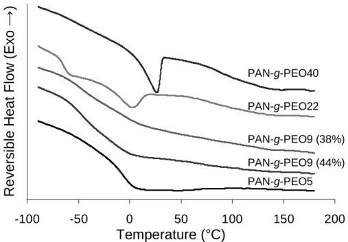
Figure 3.2. Differential Scanning Calorimetry Thermographs of PAN-g-PEO Copolymers . . . 45
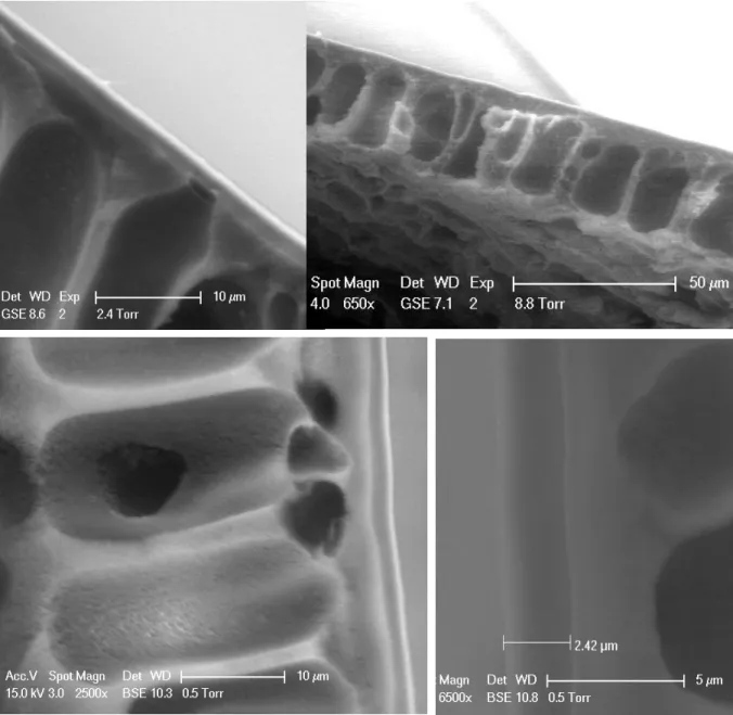
Figure 3.3. SEM Micrographs of Comb Copolymer TFC Membranes . . . 47
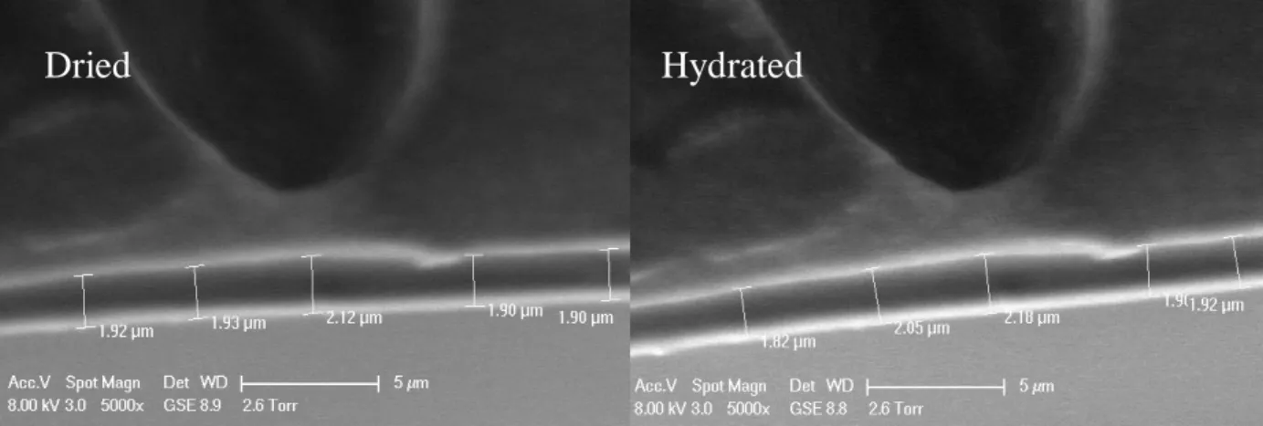
Figure 3.4. ESEM Micrographs of Dried and Hydrated Comb Coatings . . . 48
Figure 3.5. Membrane Water Contact Angles . . . 49
Figure 3.6. Carboxylate-modified AFM Tip Membrane Adhesion Force . . . 50
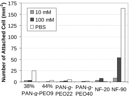
Figure 3.7. Short Term Biofouling Resistance of Membranes (Bacterial Adhesion) . . . 51
Figure 3.8. Microscopy Images of Bacteria Adhered to Membranes . . . 51
Figure 3.9. Bovine Serum Albumin Fouling Experiment Membrane Permeabilities . . . 53
Figure 3.10. Temperature and Pressure Effects on PAN-g-PEO NF Membrane Permeability . . . 55
Figure 3.11. Dependence of Permeability on Solvent Quality for PEO . . . 56
Figure 3.12. Normalized Membrane Permeability vs. Temperature and Pressure . . . 58
Figure 3.13. Retention of Rigid Molecular Probes in Deionized Water . . . 60
Figure 3.14. Retention of Rigid Molecular Probes in 0.2 M NaCl . . . 62
Figure 3.15. Comparison of Rigid Molecular Probe Retentions in DI Water and 0.2 M NaCl . . . 62
Figure 3.16. Temperature Response of Direct Red Retention by PAN-g-PEO Membranes . . . 63
Figure 3.17. Acid-induced Changes in Methyl Orange Retention and Permeability . . . 64
Figure 3.18. Acid Effects on Dye Retention and Permeability of PAN-g-PEO Membranes . . . 65
Figure 3.19. Base Effects on Dye Retention and Permeability of PAN-g-PEO Membranes . . . 66
Figure 3.20. Acid Hydrolyzed PAN-g-PEO40 Membrane BSA Fouling Experiment . . . 67
Figure 4.2. Analytic Ultracentrifuge Traces of Coated Nanoparticle Feed and Retentate Solutions . . 72
Figure 4.3. Retention of Fluorophore-Labeled Peptides . . . 74
Figure 4.4. Contributing factors in peptide retention . . . 75
Figure 4.5. Comparison of Membrane Retention of Peptides by Fluorophore Type . . . 76
Figure 4.6. Comparison of Fluorophore Structure . . . 77
Figure 4.7 Schematic of the Peptide Filtration . . . 78
Figure 4.8. Separation of Two Peptides by PAN-g-PEO9 Comb Membrane Filtration . . . 78
Figure 5.1 Conceptual Comparison of Charged Terpolymer and Nanotube Membranes . . . 82
Figure 5.2. Average Salt Retention and Permeability of Membranes by Type . . . 84
Figure 5.3. Pressure Dependence of Membrane Salt Retention . . . 85
Figure 5.4. BSA Fouling Resistance of Terpolymer Nanofiltration Membranes . . . 87
Figure 6.1. Model of PAN-g-PEO Membrane Size Exclusion at Two Length Scales . . . 92
Figure A.1. BSA Fouling Resistance of PAN-400 UF Base Membrane . . . 107
List of Tables
Table 2.1. Monomer Content and PAN-g-PEO Characteristics . . . 32
Table 2.2. Monomer Content and Comb Terpolymer Characteristics . . . 33
Table 2.3. Water Soluble Molecular Probes and Their Properties . . . 39
Table 2.4. Fluorophore-Labeled Peptide Probes . . . 41
Table 3.1. PAN-g-PEO Polymer Characteristics . . . 45
Table 4.1. Properties of Membranes Used in Peptide Filtration Experiments . . . 77
Table 5.1. Amphiphilic Graft Terpolymers and Terpolymer Membrane Properties . . . 83
Table 5.2. Double Layer Membrane Properties . . . 88
Table 6.1. Estimated PEO Domain Size and Mesh Size . . . 93
Table A.1. PAN 400 Properties . . . 107
Acknowledgements
I would like to acknowledge and extend thanks to some key people who have shaped my experiences here. First, to Professor Anne Mayes for her patience and unflagging attention to detail, for the high standards she holds herself to and expects from others, and for her candid observations. She has been a loyal advocate and a blunt critic, an insightful advisor and an endless optimist;
Second, to Professor Michael Rubner for taking the Mayes refugees under his wing, for dispensing regular doses of reality into my perspective, and for being an excellent administrator of so many important programs, particularly the CMSE/MPC summer internship that introduced me to Materials Science and MIT;
To Ayşe Asatekin Alexiou, who is appropriately first in so many alphabetical lists of friends, and never accepts without a fight the stolid, silent passing of friends (or strangers) in the hallway that so many of us take for granted; who knows, like only a few do, what it is to be "insane in the membrane", and who successfully grants respect and dignity to those she meets without feeling her own considerable competence is threatened thereby;
To Al for passing on such crucial wisdom as the art of playing dart; to Will for peptides and quiet brilliance; to Bill Phillip for “forcing” the issue; to Randy Carney for reigning over his fiefdom with great wisdom and order, and nanostuff; to the Cohen/Rubner collective and the former Mayes group members for their insights; to my committee for making time and taking the position seriously in spite of hectic schedules;
To Brian Kinghorn for his tireless friendship through thick and thin and many miles;
To Carolee and Gary Lovell, for their habitual inability to conceive of me failing, and puzzled but unquestioned love when i so often do;
To Professor J. Walter Woodbury and Grandma Betty the entomologist, who are behind whatever principle of intelligence i have attained. Grandpa: in a most unexpected way, the “family business” of membrane research passed to another generation…
To Patrick Boisvert and Dr. Shiahn Chen for their assistance with electron microscopy; And finally, to the many friends who have so frequently brightened Boston's greyer days. The financial support for this work was provided by the WaterCAMPwS, a Science and Technology Center of Advanced Materials for the Purification of Water with Systems under National Science Foundation agreement number CTS-0120978. Funding was also provided
via NSF fellowship and DuPont-MIT Alliance, for which i am most grateful. The MRSEC
Shared Experimental Facilities were vital for characterization. They are supported by the National Science Foundation under Award DMR-0213282.
1. Overview
This thesis is about the basis and control of the properties of filtration membranes* based on amphiphilic graft copolymers. The membranes have been a topic of some extended focus in our group which applied principles of polymer morphology to important engineering challenges. These challenges and the motivation for the work will be discussed presently, complemented by a discussion of membrane filtration processes. After this context is established, the history of amphiphilic graft copolymer materials in membranes will be reviewed as a preface for the research presented herein. The aim of the project was to control the steric (size) and charge selectivity of polyacrylonitrile-graft-poly(ethylene oxide) membranes and characterize their filtration properties for new applications.
1.1. Introduction
Two important trends, the exponentially growing global demand for fresh water and the rapid advances in biotechnology, are motivating interest in technologies that can selectively remove components of aqueous feeds. Because of their scalability and versatility, polymer filtration membranes have been employed across the spectrum of applications, from those characterized chiefly by volume and cost considerations (e.g. textile dye recovery [1,2] municipal wastewater treatment [3] and seawater desalination for municipal potable water [4]) to the precision fractionation of organic molecules and biocomponents in complex feeds for the pharmaceutical industry [5,6].
The charged, aromatic polyamide (PA†) selective layers of membranes used in current practice have limited utility for fractionating output streams from industrial processes and retaining small, uncharged contaminants. Increasing public interest in natural food additives, awareness of deleterious compounds in the environment, and pressure to reduce pollutants in industrial waste streams point to a need for new membrane technologies with controlled size-based separation capability at the molecular scale. Moreover, future biochemical therapies and
*
A membrane can be generally defined as a thin discrete barrier with selective permeability.
†
assays will require ever more precision, scalability, and speed in processing solutions of very small organic molecules, such as protein digests inherent to proteomics technologies.
1.2. Water and Sustainability
A dependable supply of water has been a vital issue in human history, prompting such basic inventions as dams, canals, wells, and aqueducts. Water quality is also important, with many pathogens using it as a vector for infection. A significant fraction of the over one million annual deaths due to diarrheal diseases are attributed to contaminated water, and nearly one billion people lack access to clean water [7]. The developed world expends substantial resources to create and maintain its supply: in the United States, business-as-usual infrastructure upgrades are expected to cost over $1 trillion over the next 15 years using present technology and neglecting growth; yet, many parts of the country already face anthropogenic water supply-related problems and fully developed resources, even as the population continues to expand [8]. Improvements are needed in water treatment technology.
An adequate water supply represents, then, a sustainability challenge on par with energy. The demand and provision of the two resources are inextricably linked. For example, over 50 percent of water withdrawals in the states of New Hampshire, Massachusetts, Rhode Island, and Connecticut are used for energy production purposes [8], while an estimated 24 MW of power will be consumed by a new seawater desalination plant in San Diego to produce 50M gallons fresh water per day.
1.3. Water Purification and Membranes
The significant energy cost of water purification is one of the drivers of interest in alternative technologies. Installations of thermal-based seawater desalination plants proliferated e.g. in the Middle East during the second half of the last century due to a lack of effective and competitive options. The advent of the Loeb-Sourirajan process in 1963 made polymer membranes an alternative industry for the first time [9,10]. The innovation consisted of a phase inversion precipitation of cellulose acetate which formed the bulk of the membrane material into a porous support with a thin, dense selective skin layer on one face (Figure
1.1.A). This asymmetric membrane structure had much greater permeability than the symmetric membranes produced previously.
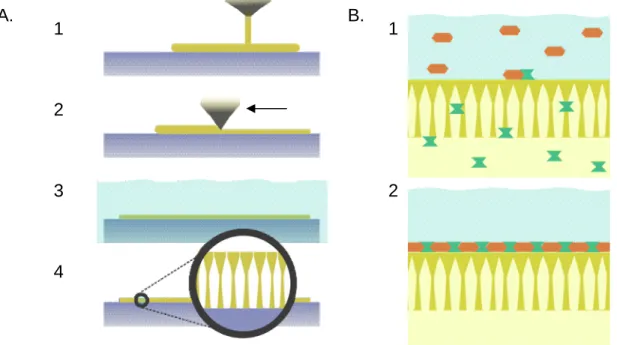
Figure 1.1. Breakthrough polymer membrane fabrication schemes include the Loeb-Sourirajan phase inversion process (A) and interfacial polymerization (B); A: a polymer solution (1) is formed into a thin, uniform layer (2) on a flat surface and immersed into a nonsolvent bath (3). An asymmetric
membrane is formed as the nonsolvent wave front advances inward from the top of the polymer
solution layer, causing a porous support to form under a thin skin (4). B: a thin-film composite membrane (2) can be formed via interfacial polymerization as a porous base membrane is first infiltrated with an aqueous solution containing one monomer, and then transferred to a solution of a second monomer in an organic solvent (1).
The cellulose acetate membrane had two shortcomings that limited its utility: sensitivity to acid, base* and elevated temperature, and insufficient salt retention to make seawater potable in a single pass. Nevertheless, a membrane industry developed around cellulose acetate reverse osmosis membranes and the phase inversion process, which was soon adapted to synthetic polymers such as polyacrylonitrile and polysulfone for other applications.
A second important membrane innovation was the interfacially-polymerized, thin-film composite (TFC) membrane, which was stable over a greater pH range, but with the tradeoff of susceptibility to oxidative attack by e.g. chlorine. The FT-30 developed at FilmTec by Cadotte in the late 1970s [11] made single-stage seawater reverse osmosis (SWRO) possible.
*
The operating range for cellulose acetate is pH 4-6 [9]. 1 2 3 4 1 2 A. B.
The process was widely adopted and is well represented in contemporary product lines (Figure 1.1.B).
1.4. Membranes
A membrane can be abstracted as a sieve. In this context, the fundamental characteristic is the size of the grating, or the smallest solute that it prevents from passing through. This is the basis for membrane classification. In microfiltration (MF, size cutoff 0.1 to 10 µm) and ultrafiltration (UF, 2-200 nm) membranes, the molecular weight cutoff (MWCO*) is determined by the size and shape of discrete pores in the membrane selective layer. Their range of MWCO makes them suitable for removing particulates, macromolecules and microorganisms, and these membranes are commonly used for the sterilization of water and clarification of beverages [9].
Reverse osmosis (RO) membranes have no discrete pores. The selective (or “active”) layer is a dense polymer film that allows water to permeate by diffusion through the free volume between the polymer chains. The effective size cutoff is less than half a nanometer, making reverse osmosis membranes capable of retaining even small salts (e.g. sodium and chloride ions in seawater, with hydrated radii of ~0.7 nm [13]). However, molecules with a high affinity for the membrane material may dissolve into the thin selective layer itself and diffuse across, a process known as solution-diffusion [14].
The most recent category of membranes fills the gap between RO and UF, that is, from 0.5 nm to 2 nm. Although these nanofiltration (NF) membranes may be considered to have discrete pores, these are not directly formed by the phase inversion process introduced in the previous section, which is used for UF and MF membranes [15]; typically, the membranes are created by the interfacial polymerization of an aromatic polyamide on the microporous surface of an asymmetric UF or MF base (Figure 1.1.B) [9], a structure referred to as a thin-film composite (TFC). Although NF membranes span the continuum from dense RO to microporous UF, the combination of small scale, charged groups in the active layer, and
*
The molecular weight or size cutoff is commonly defined as the size of the smallest molecule which is retained 90% by the membrane.[12]
microporosity lead to different barrier characteristics than either RO or UF. Salts which are excluded by RO membranes are selectively retained in NF through a combination of electrostatic forces and steric repulsion. As a consequence, the ionic strength of the solution and the ion valences are cofactors with hydrated ionic radii (i.e. size) [16,17], and NF membranes are capable of passing small, uncharged solutes while retaining salts.
This two-dimensional (electrostatic and steric) parameter space for NF membrane selectivity holds much potential for precise separations in the biotechnology and chemicals industries which has yet to be fully realized [5,6]. Present NF applications include the recovery of dyes from textile wastewater [1,2], various food component fractionations and concentration of juice and dairy products [18-21], and water purification. Existing water purification processes implemented with RO or UF, such as ultrapure water for the semiconductor industry, seawater desalination, and membrane bioreactors, are also being enhanced by the improved permeability or better selectivity of NF membranes [3,4,22].
1.5. Metrics of Membrane Performance
It has been seen that solute retention and solvent permeability are important metrics for a membrane; a molecular weight cutoff (MWCO) has been defined as the smallest molecule that is retained 90% by a membrane. In the context of this thesis, retention or rejection is defined as:
cper cret
R 1 / (1),
where cperis the concentration of the solute in the permeate (that which permeates through the
membrane), and cret is the concentration of the solute remaining in the retentate. This represents the effective selectivity of the membrane in the system; the intrinsic retention by the membrane will be higher due to concentration polarization (1.5.1), and higher or lower due to the finite permeation time of a membrane with finite thickness in a changing system.
bewildering and bizarre array of units used for permeability and flux in the membrane industry. Here, permeability will be reported as liters permeate per square meter of membrane per hour per megapascal, L/m2hMPa (also LMH/MPa). Thickness-normalized permeabilities are also reported for various TFC membranes in units of LMH-µm/MPa.
1.6. Membrane and Membrane Process Limitations
1.6.1. Concentration Polarization
When a solvent is selectively removed from a thin layer of solution at the surface of the membrane, the retained solutes are concentrated and begin to diffuse away from the membrane into the bulk of the solution. The greater the flux across the membrane, the higher the polarization becomes. This buildup at the membrane surface decreases its selectivity and permeability. The phenomenon can be mitigated by not relying on diffusion to mix the solution—by designing the process to have a cross-flow of feed solution or agitation.
1.6.2. Fouling
A more general problem for membranes is the reduction of permeability over time due to clogging by the feed solution. This fouling may be caused by the precipitation of insoluble compounds as they are concentrated by filtration (scaling), the consolidation of retained feed components into a compacted gel layer (caking), the adhesion and growth of microorganisms on the surface (biofouling), or the adsorption of solutes directly onto the surface [23].
The latter is known as adsorptive fouling. When a hydrophobic membrane surface is presented with an aqueous feed of organic components, it may be thermodynamically favorable for the solutes to adsorb on the membrane, thereby reducing the energy of the interface [24]. Adsorption is a particularly challenging problem in membrane systems because it is not subject to reversal by mere mechanical means, such as back-flushing [23]. Therefore, a regimen of chemical cleaning has become a part of many membrane processes, balancing the costs of decreased membrane permeability (e.g. lower capacity, higher energy consumption) with the reduction of membrane lifetime and system downtime necessary for a regular cleaning step.
The hydrophobicity of synthetic polymer membranes developed since the original cellulose acetate membranes has made adsorption an increasingly important problem, while membrane inefficiency due to fouling has motivated much research [25-28]. Other membrane properties that affect fouling are roughness and charge density, both important characteristics of polyamide TFC NF membranes.
Biofouling is a more complex process due to the active antagonists (microbes). After initial adhesion to the surface, bacteria may form a biofilm and specialize to produce additional components that will accelerate membrane fouling and, particularly in the case of natural polymer-based membranes such as cellulose acetate, membrane decomposition [29-31]. Strategies for preventing biofouling have targeted prevention of initial adhesion and targeted antimicrobial agents to prevent proliferation [32-34].
1.6.3. Fouling and Selectivity
The problem with fouling is the effect it has on membrane permeability. This has been introduced simplistically as an impediment to the passage of solvent, but it is in reality much more complex. For example, hydrophilic foulants may in fact increase solvent permeability under certain conditions [24]. Equally important is the way that fouling affects the selectivity of the membrane. One intuitive effect is the narrowing or partial blockage of pores in microporous membranes, which reduces the size cutoff [26,27,35]. This effect is predominant in MF and UF membranes, but extends even to the NF regime, where it can increase the size-based rejection of salts [27]. Competing effects make NF fouling more complex, depending not just on solute size but on the chemical properties of the membrane, the foulant, the solute, and the solution. In direct competition to pore size reduction is cake-enhanced concentration polarization, wherein cake fouling on the surface hinders the diffusion of concentrated solutes back into the bulk solution. This leads to a reduction in retention for molecules compatible with the membrane material (i.e. those that may follow a solution-diffusion mechanism) due to the relative decrease in water flux to solute flux [14,36], but may reduce the MWCO of charged species and those incompatible with the membrane (e.g. hydrophilic or hydrophobic) [26].
1.6.4. Selectivity
Regarding the nanofiltration realm, it has been observed that the methods for producing these membranes (i.e., interfacial polymerization to create a thin film composite) provide little control over the size and distribution of the nanopores, leaving a gap in the continuum of membranes with precise size cutoffs between ~1 nm and ~10 nm [16]. Van Der Bruggen et al. reviewed several models of nanofiltration membrane selectivity in the context of small organic molecule solutes and polyamide TFC NF membranes and found that some common models (that assume a uniform pore size) are overly idealized [12]. They concluded that a model based on a log-normal distribution of pore sizes is the most useful to predict retention in practical applications. Another study that found the log-normal model a best fit for the experimental data measured pore radii for two TFC membranes to range from 0.26–0.73 nm [37]. In general, uniformity of pore size is desirable as it increases membrane selectivity and permeability [38].
1.7. Improving Membranes
1.7.1. Fouling Resistance
Resistance to many foulants can be imparted by a coating or surface modification that decreases membrane roughness and increases hydrophilicity, but the additional membrane resistance may not be compensated by the averted fouling [39-41], and may decrease pore size [39]. For example, Ulbricht et al. used a low temperature plasma to etch or graft 2-hydroxy-ethyl methacrylate (HEMA) onto UF membrane surfaces. They found that the etch decreased the retention while increasing the permeability and hydrophilicity of the polysulfone membranes. By grafting hydrophilic polymer onto the membrane after activation by the plasma, they were able to improve the fouling resistance and permeability of both polysulfone and polyacrylonitrile membranes, while also increasing retention [33].
Kochkodan et al. modified polysulfone and poly(vinylidene fluoride) membranes by grafting on hydrophilic, charged or quaternized ammonium moieties. This versatility was used to make general observations about biofouling of membranes. They found that smoothness and hydrophilicity reduce fouling, while the absence of charge makes bacteria more easily detach.
The most effective modifier to prevent biofouling was the quaternized ammonium group, which disrupts directly the development of the bacteria into a biofilm [34].
To avoid modifying the membrane permeability or selectivity, antifouling components can be directly incorporated during the membrane production process. In an early example, Nunes et
al. started with a hydrophilic PVDF ultrafiltration membrane and produced a fouling-resistant
membrane of the desired size cutoff by coating it with a nylon-poly(ethylene oxide) (PEO) block copolymer [42]. By varying the blend of two copolymers and concentration of the coating solution, they were able to adjust the MWCO down to 900 g/mol. This active layer reduced the permeability to 64 LMH/MPa, one tenth that of the base membrane, but gave the membrane comparable permeability and fouling resistance to a control hydrophilic acetate UF membrane. In the intended application, the filtration of oily water, the coated membrane maintained a higher permeability than the base membrane within minutes of starting the filtration.
Later studies on the mechanics of fouling found that end-attached PEO brushes of sufficient density can completely inhibit protein binding to a surface over a finite period of observation [43-45]. Both Irvine et al. and Sofia et al. evaluated inhibition of protein adsorption by surface-grafted linear and star PEO, and reported complete protein resistance in higher density grafts [43,45]. Irvine also used neutron reflectometry to find the volume fraction of PEO at different distances from the surface. From this information an explanation could be given for imperfect protein resistance by a dense star PEO-grafted surface: the PEO density at the star-grafted surface was lower than at larger distances from the surface due to the branched star, thus allowing proteins to adsorb onto the surface after permeating through the denser region.
Norde and Gage elaborated on the role of PEO graft spacing and brush thickness using bovine serum albumin and human blood plasma proteins as probes [44]. They confirmed the importance of graft spacing less than the size of the protein for effective resistance, but also observed a decrease in protein resistance for thicker brushes at a given graft density, and enhanced protein adsorption with tenuous (sparse) brushes. They hypothesize that there is a weak attractive interaction between PEO and the proteins, and that the widely known protein
resistance of dense PEO brushes is due to a high activation energy to enter the brush. Bosker
et al. reached the same conclusion about the weak attraction of PEO to a model protein after
characterizing the resistance of bimodal PEO brushes to bovine serum albumin [46]. The strong steric hindrance that PEO brushes pose to permeating solutes will be important in this study.
PEO remains one of the most effective anti-fouling materials today [39], and is frequently studied as a means to impart fouling resistance to membrane surfaces as a cross-linked gel [47-49], grafted layer [32,39,50-52], or self-organizing additive or coating [53-63]. A subset of the latter group will be addressed in more detail in section 1.8.
1.7.2. Controlled and Uniform Pore Size
Researchers have attempted to address the limitations of polyamide NF membranes using selective layers that exploit self-assembly phenomena, such as the coordination of metal ligands into molecular squares [64] or the morphologies of liquid crystalline [16], graft copolymer [54,55,53], and block copolymer materials [65,66], and the regular packing of a protein in space [67]. Others have created membrane pores using discrete structures such as carbon nanotubes [17] and aquaporin proteins [68], and by etching radioactively-ionized tracks in dense films [69] or patterned silicon substrates [38].
The pore sizes available using these techniques range from the reverse osmosis regime (< ~0.7 nm) to ultrafiltration (> 2 nm). The membrane pore size of interest for this work is ~1-5 nm, the interface between nano- and ultrafiltration. One of the precise pore fabrication methods that covers that range is the technique of Martin and coworkers [70,71], which can create pores from 50 nm to 1 nm by narrowing polycarbonate track-etched membrane* pores
via electroless deposition of gold to a desired aperture. Different size-based separations have
been demonstrated, including small organic molecules and large proteins. The researchers also adsorbed thiol-terminated PEO chains on the gold and found that it prevented the pores
*
The work in the early 1970s on track-etched membranes [69] is another breakthrough in the field due to its ability to produce regular pores down to nanometers in diameter by exposing polymer films to ionizing radiation and then etching the resulting damaged tracks. The main disadvantages to the membranes are due to the
stochastic mechanism for creating the pores: a tradeoff must be made between low porosity and many connected pores (i.e. increased size dispersity).
from clogging due to protein adsorption [70].
Another interesting example is the recent work of Peng et al. [67], in which crosslinked stacks of the 12 nm globular ferritin protein were used to create membranes with 1.7-2.2 nm effective pore size and extremely high pure water permeability (90,000 LMH/MPa compared to 8,000 LMH/MPa for the Sepro PS-20 UF membrane and 75 LMH/MPa for the FilmTec NF-90). The membranes were stable across a high range of pH and many solvents. Because the protein in the membrane is inherently charged, they filtered both charged proteins and uncharged cyclodextrins to estimate the size cutoff, and found that the electrostatic repulsion decreased the effective pore size for charged probes by ~0.2 nm (i.e. about 10%). The “ultrafast permeation” was attributed to a combination of the thin (40 nm) membrane, and the order-of-magnitude smaller effective thickness due to the reduced transition length of the smallest “pore”: the narrowest point in the interstitials of the proteins. A defect-free membrane so thin was possible due to the way the proteins are assembled, and is a strength of membrane designs that assemble macromolecules directly into a selective layer [67,72]. It is reasonable to assume that different effective pore sizes could be achieved through the use of different proteins, but no specific statements were made by the researchers regarding that, the scalability of the process, or the fouling resistance of the membranes.
1.8. Amphiphilic Graft Copolymer Nanofiltration Membranes
Because selectivity and fouling resistance remain two of the most important challenges to membrane science [73], efforts have been made in our lab to combine self-assembly and PEO brushes to create precision nanosieves [55,53,56,57]. The NF membrane designs were based on amphiphilic comb copolymers (Figure 1.2 (A)) incorporating PEO as the comb “teeth”, and poly(vinylidene fluoride) (PVDF), or polyacrylonitrile (PAN), as the hydrophobic spine.
PVDF-graft-polyoxyethylene methacrylate (PVDF-g-POEM) and polyacrylonitrile-graft-poly(ethylene oxide) (PAN-g-PEO) (Figure 1.3) were both shown to microphase separate into a bicontinuous network structure at the 1 nm scale. The PEO side chains fill the "nanochannels" that interpenetrate the rigid PVDF or PAN matrix (Figure 1.2 (B)), allowing
the passage of water molecules and retention of solutes larger than the nanochannel diameter.
Figure 1.2. A conceptual representation of a single amphiphilic comb copolymer chain (A) with hydrophilic PEO side chains in black and hydrophobic backbone in orange; in bulk (B), the two microphase separate into a bicontinuous structure with PEO-lined “nanochannels” acting as pores for water transport through the rigid matrix.
Nanosieving with a PVDF-g-POEM-coated PVDF ultrafiltration (UF) membrane was demonstrated through the separation of like-charged molecular dyes [53]. It was also shown that reducing the solvent quality of the feed solution for PEO increases the effective size cutoff of the NF membrane by collapsing the swollen PEO chains within the nanochannels [56,57]. PAN-g-PEO comb copolymers could likewise be formed into thin film composite (TFC) NF membranes when coated onto a commercial PAN UF support. The PAN-based NF membranes exhibited separation capability similar to their PVDF analogues [55]. Both comb chemistries displayed complete resistance to irreversible fouling in dead-end filtration studies with model organic foulants at concentrations of 1g/L and above [55,53,58,59,74]. Other researchers have created PEO graft copolymers for use as biocompatible materials [32,75], electrolytes [76], medical imaging contrast [77], etc.
x 1-x N O O O n 1-x n A B x F F F O O O F
Figure 1.3. Amphiphilic graft copolymers incorporating poly(ethylene oxide) in the side chains: (A) poly(vinylidene fluoride)-graft-poly(oxyethylene methacrylate) (PVDF-g-POEM) and (B) polyacrylonitrile-graft-poly(ethylene oxide) (PAN-g-PEO).
A B
PVDF is a more thermally and chemically robust material than PAN, but carries a higher cost*. Synthesis of PVDF-g-POEM is via an atom transfer radical polymerization (ATRP)-like mechanism [79], which requires a copper complex catalyst that can be difficult to remove from the product [80] and is difficult to scale up. Due to its more facile free radical synthesis, the PAN-based comb copolymer was studied in this work.
1.9. Outline
Because the fouling resistance, permeability and regular pore size of amphiphilic graft copolymer membranes show promise to overcome the greatest limitations of NF membranes, the technology has the potential to improve established membrane systems and open applications not possible with existing membranes. The utility of these membranes will hinge upon the degree to which membrane selectivity can be specified and retained during filtration operations. This work explores the control of PAN-g-PEO NF membrane steric and electrostatic selectivity, and the possible applications these enable.
Chapter 2 describes the experimental methods, including synthesis, polymer characterization, membrane fabrication, and membrane characterization.
Chapter 3 investigates the role of PEO side chain length, PEG casting additive, and filtration feed solvent quality on the permeability and effective pore size of PAN-g-PEO NF membranes through the filtration of rigid dyes of varying size from ~0.6-1.2 nm [55,53,57]. The fouling resistance of these membranes is further assessed by filtration of bovine serum albumin (BSA) and supplemental colloidal force spectroscopy studies measuring the attraction of a carboxylate-modified latex particle, as a model foulant [58,59,74], to the membrane coatings. Bacterial adhesion tests are conducted to compare the short-term biofouling resistance of the membranes with the adsorptive fouling [81]. The membranes are also subjected to acidic and basic conditions typical of those used to clean industrial membrane systems to ascertain the susceptibility of the PEO linkage, an ester bond, to hydrolysis under those conditions.
*
Resin prices are reported to be $7.2/lb for PVDF and $1.3/lb for general acrylics at annual volumes of 200,000 lbs and 2 million lbs, respectively [78].
In Chapter 4, potential applications of the membrane are demonstrated using two types of probes increasingly important in biotechnology: metal nanoparticles and fluorophore-labeled peptides.
Chapter 5 reports modifications to the comb copolymer chemistry that change the electrostatic component of its selectivity. The charged terpolymer membranes so produced have greatly increased salt retention properties but reduced fouling resistance.
Finally, Chapter 6 summarizes the findings and concludes the discussion with a review of potential applications for the membranes.
2. Experimental Methods
2.1. Introduction
The experimental portions of this work can be divided into three categories: material synthesis and characterization, membrane fabrication and characterization, and application development. A brief summary of each follows.
2.1.1. Material Synthesis Considerations
Amphiphilic graft copolymers with PEO side chains can be produced via a “grafting from” process, requiring activation of a site on the polymer backbone and extension of the chain with monomer, or by “grafting through”, which uses a PEO macromonomer (a macromolecule with a pendant group that can participate in a polymerization (Figure 2.1)) in the synthesis of the backbone [82]. The latter approach has as an outcome grafted PEO of consistent length, an important characteristic for this project. PEO macromonomers have been studied for several decades [83-87] due to the interesting and useful properties of PEO and PEO copolymers as coatings [43,88,44,89], catalyst media [90], emulsifiers [91], electrolytes [92], and membranes [55,53,57,58,81,93,60]. O O O n O H O n
+
O Cl TEA 0 °C, DCMFigure 2.1. Synthesis scheme for an acrylate-based PEO macromonomer in triethylamine and dichloromethane.
PEO macromonomers can be prepared directly by the reaction of e.g. acryloyl chloride with monofunctionalized PEG* (Figure 2.1) [87,94,82]. This approach was pursued initially in this project to produce a PEO4 acrylate macromonomer, which was used to make PAN-g-PEO with monodisperse tetrameric side chains of PEO (PAN-g-PEO4). Though the monodispersity
*
Traditionally poly(ethylene glycol) (PEG) has been used to refer to shorter chains of ethylene oxide, and PEO for high molecular weight macromolecules. The terms will be used accordingly here except when referring to grafted chains.
was ideal to permit exact comparison of combs of different side chain length, the lack of availability of longer monodisperse PEG chains and the commercial availability of (polydisperse [88]) methacrylate-capped PEO macromonomers (POEM) in a range of molecular weights eventuated a change to POEM. While this change was consistent with the underlying motivations for using PAN (industrial scalability and cost), it produces a different PAN-g-PEO backbone than that studied previously as an antifouling water filtration membrane [55,57,58,74]. Acrylates and acrylonitrile have similar activities and the acrylate PEO macromonomer can be expected (and seen [95]) to form a random copolymer with acrylonitrile. The higher activity of methacrylate ester is one possible source of trouble, as blockiness in the copolymer could introduce defect sites in a membrane surface that nucleate fouling. However, due to reduced mobility and steric hindrance, solvent quality can be as significant as monomer moiety reactivity in determining the outcome of copolymer synthesis with macromonomers [96]. An important observation to be made is whether POEM-based PAN-g-PEO has the same desirable properties as acrylate-based PAN-g-PEO.
2.1.2. Membrane Fabrication Considerations
The many relevant parameters in the membrane casting and fabrication process have led to a common perception that it is a “black art” [9]. The conceptually simple but similarly nuanced coating process used to make TFC membranes is also prone to inconsistencies due to similar factors: variation in polymer properties, coating solution concentration and viscosity, coagulation bath composition, temperature, humidity, contaminants, airflow, etc. The optimization of this process was not a focus of this work; however, it is of more than academic interest due to the proposed application of the described membranes, where existing (and optimized) commercial membranes may already be available. Accordingly, properties that are dependent on such an optimization (e.g. permeability) will be discussed in that context. In general, the experimental approach was to err on the side of thicker coatings to minimize defects and produce reliable retention data.
2.1.3. Applications
Although nanotechnology has entered the common vernacular, the touted convergence of molecular and mesoscopic scale has not (and cannot) lead to a completely smooth continuum
from nano- to mesoscopic materials and methods. For example, coated nanoparticles, which are commonly available in > 5 nm suspensions, are not found in subnanometer sizes. Uncoated particles (available down to ~0.6 nm diameters) readily aggregate when concentrated. At the other side of the divide is the rigid molecular dye which, at sizes larger than a nanometer, tends to be insoluble or aggregate.
Many self-assembly phenomena that might be used in fabricating a membrane selective layer also tend to one extreme. At the angstrom length scale are voids in molecular assemblies [64] and between liquid crystalline domains [16], while etched, microphase separated block copolymers [65] have pores tens of nanometers in diameter. A similar gap exists in dimensional analysis (e.g. dynamic light scattering, small- vs. wide-angle x-ray scattering (SAXS/WAXS) and (as has been discussed) polymer membranes.
As will be seen, by virtue of the grafted morphology, this gap is the regime where the PAN-g-PEO NF membranes operate, making them valuable for separations intended to provide strictly nanoscopic products.
2.2. Materials
2.2.1. Monomers, Reagents and Polymeric Casting Additives
The initiator and monomers, azobisisobutyronitrile (AIBN), acrylonitrile (AN), poly(ethylene glycol) methyl ether methacrylate, also known as poly(oxyethylene) methacrylate (Mn~300 g/mol, POEM5 (5 EO repeats); Mn~475 g/mol, POEM9 (9 EO repeats); Mn~1,100 g/mol, POEM23; Mn~2080, POEM45), potassium 3-sulfopropyl acrylate (SPA), N,N-dimethyl-N-(2-methacryloyloxyethyl-N-(3-sulfopropyl) ammonium betaine (SPE), and casting additives poly(acrylic acid) (PAA) and oligimeric PEO (poly(ethylene glycol) (Mn~400 g/mol, PEG9;
Mn~1,000 g/mol, PEG23; Mn~2000 g/mol, PEG45)), were purchased from Sigma-Aldrich (St.
Louis, MO). POEM and AN were passed through a column of basic alumina to remove inhibitor before use.
The solvents—dimethyl formamide (DMF), dimethyl sulfoxide (DMSO), deuterated dimethyl sulfoxide (DMSO-d6), isopropanol, ethanol, methanol, acetic acid, pH 11 buffer, and
phosphate buffered saline (PBS, pH 7.4) —were purchased from VWR (West Chester, PA) and used as received. Pre-synthesis nitrogen purge gas was of high purity grade (AirGas).
2.2.2. Membrane Characterization Probes
Rigid molecular probes Acid Fuchsin, Alizarin Yellow GG (AY), Amaranth, Direct Red 80 (DR80), Chicago Sky Blue (CSB), Reactive Red 120 (RR120), Acid Blue 45, Methyl Orange, 4-(phenylazo)benzoic acid, and benzoic acid were also purchased from Sigma-Aldrich.
Peptides labeled with 5-carboxytetramethylrhodamine (5-TAMRA) or 5-carboxyfluorescein (5-FAM)—p60c-src Substrate 1, Glycogen Synthase derived peptide, Abltide, Tyrosine Kinase Peptide 3, Tyrosine Kinase Peptide 1, Bak - BH3, Bid BH3, Peptide II, and Neuropeptide Y (13 - 36)—were purchased from Anaspec (Fremont, CA).
Bovine serum albumin was purchased from SeraCare (Milford, MA). Sodium chloride, sodium sulfate and calcium chloride were purchased from VWR (West Chester, PA). Deionized (DI) water was obtained from a Millipore Milli-Q system.
Water dispersions of metal nanoparticles were acquired in the form of 2 nm gold colloid (British Biocell International), 0.7 nm silver colloid (Colloidal Science Laboratory, Westampton, NJ) and ~2 nm gold nanoparticles coated with sodium 11-mercaptoundecanesulfonate and octanethiol ligands in a 2:1 ratio (prepared by Randy Carney in the lab of Prof. F. Stellacci at MIT) [97]. An aliquot of gold colloid was dried under vacuum and redispersed in methanol using a Branson 2210 sonicator (Danbury, CT). The rest of the probes were used as received.
2.2.3. Membranes
PAN-400 ultrafiltration and NF-20 nanofiltration flat sheet membranes were purchased from Sepro Membranes, Inc. (Oceanside, CA) and used as the base membrane and control, respectively. NF-90 flat sheet membrane was obtained from FilmTec (Dow; Edina, MN). All
control membranes were soaked in DI water for 48 hours to hydrate them prior to use. The NF controls are both thin-film composite membranes with interfacially polymerized charged polyamide active layers.
2.3. Synthesis and Characterization of Comb Copolymers
2.3.1. Synthesis of Polyacrylonitrile-graft-poly(ethylene oxide)
Polyacrylonitrile-graft-poly(ethylene oxide) (PAN-g-PEO) was synthesized by free radical polymerization using AIBN as an initiator (Figure 2.2). The monomers, 30 ml DMSO, AIBN, and a stir bar were added to a round bottom flask, which was then sealed with a rubber septum and purged with nitrogen gas for 20 minutes while stirring. The flask was moved to an oil bath regulated to 60 °C and stirred for 20 hours. The reaction was quenched with excess 4-methoxyphenol (MEHQ) and then the polymer was precipitated by pouring the solution gradually into 10 times the volume of water. The precipitant was collected by vacuum filtration and dried in a vacuum oven at 50 °C, then redissolved in sufficient DMSO to permit free flowing of the solution (~30 ml) into water to purify the product.
x 1-x N O O O N n O O O n
+
AIBN 60 °C, DMSOFigure 2.2. Synthesis of PAN-g-PEOn by free radical polymerization via the poly(oxyethylene) methacrylate (POEM) macromonomer route.
Because the resulting copolymer was consistently enriched in macromonomer, monomer ratios were initially chosen to contain 35% PEO, and then adjusted in subsequent syntheses as needed to obtain combs with ~39 wt.% PEO content. Approximately 100 mg (0.5 mol%) initiator was used except in the case of POEM5-based reactions, which tended to form a cross-linked gel (due to difunctionalized macromonomers [83]) unless the initiator and monomer concentration were reduced by half. This alteration reduced the yield substantially (consistent with the findings of Garcia et al. using DMF [84]). It also increased the molecular weight of the PAN-g-PEO5, relative to the other comb copolymers, as expected for a free radical synthesis with radical-radical annihilation as the predominant termination step.
1.0 1.5 2.0 2.5 3.0 3.5 4.0 4.5 5.0 5.5 ppm
Current Data Parameters NAME s131 P(AN-r-SPA-r-POEM45) EXPNO 1 PROCNO 1 F2 - Acquisition Parameters Date_ 20100225 Time 4.12 INSTRUM spect PROBHD 5 mm QNP 1H/13 PULPROG zg30 TD 65536 SOLVENT DMSO NS 64 DS 2 SWH 8278.146 Hz FIDRES 0.126314 Hz AQ 3.9584243 sec RG 228.1 DW 60.400 usec DE 6.00 usec TE 294.2 K D1 10.00000000 sec TD0 1 ======== CHANNEL f1 ======== NUC1 1H P1 13.88 usec PL1 0.00 dB SFO1 400.1324710 MHz F2 - Processing parameters SI 65536 SF 400.1300220 MHz WDW EM SSB 0 LB 0.30 Hz GB 0 PC 1.00 NL-s131 P(AN-r-SPA-r-POEM45) N O O O O HH HH HH H H H O CH3 H H b b a a b C-CH3 DMSO-d6 H2O d d e e f f g g PEO n-2 1.0 1.5 2.0 2.5 3.0 3.5 4.0 4.5 5.0 5.5 ppm
Current Data Parameters NAME s131 P(AN-r-SPA-r-POEM45) EXPNO 1 PROCNO 1 F2 - Acquisition Parameters Date_ 20100225 Time 4.12 INSTRUM spect PROBHD 5 mm QNP 1H/13 PULPROG zg30 TD 65536 SOLVENT DMSO NS 64 DS 2 SWH 8278.146 Hz FIDRES 0.126314 Hz AQ 3.9584243 sec RG 228.1 DW 60.400 usec DE 6.00 usec TE 294.2 K D1 10.00000000 sec TD0 1 ======== CHANNEL f1 ======== NUC1 1H P1 13.88 usec PL1 0.00 dB SFO1 400.1324710 MHz F2 - Processing parameters SI 65536 SF 400.1300220 MHz WDW EM SSB 0 LB 0.30 Hz GB 0 PC 1.00 NL-s131 P(AN-r-SPA-r-POEM45) N O O O O HH HH HH H H H O CH3 H H b b a a b C-CH3 DMSO-d6 H2O d d e e f f g g PEO n-2
Figure 2.3. 1H Nuclear Magnetic Resonance (NMR) spectrum of PAN-g-PEO with all peaks matched to their corresponding protons; the ester protons (a), backbone tail protons (b), and PEO protons are sufficient to obtain the PEO content and average PEO side chain length.
2.3.2. Chemical Characterization
The PEO content was determined by 1H nuclear magnetic resonance (NMR) spectroscopy with a Bruker DPX 400 spectrometer (Figure 2.3). DMSO-d6 was used as the solvent. Peak
assignment follows from expected chemical shifts, known solvent shifts [98], and observation of the peak-broadening effect that proton attachment to kinetically slow chains causes (see e.g. the sharp singlet for the terminating PEO ether methyl group (e) and the resolution of the triplet for the relatively unhindered last methylene of the PEO (g) compared to the broadened first (a) and second (d) PEO methylenes). The ratio of the ester (COOCH2) protons (~4.2 ppm) of POEM to the PEO protons (3.5, 3.6 ppm) was used to find the average side chain length. The ratio of total PEO protons to total backbone tail protons (1.7-2.2 ppm) was used to calculate the PEO content, which was maintained at ~40 wt.% for the different side chain lengths. The molecular weight was measured by gel permeation chromatography (GPC) using a Waters Breeze 1525 HPLC system equipped with two Polypore columns operated at 75 °C, series 2414 refractive index detector, series 1525 binary HPLC pump, and 717plus autosampler with DMF as the eluent, calibrated with poly(methyl methacrylate) (PMMA)
standards. PEO contents and molecular weights of the comb polymers are reported in Table 2.1.
Table 2.1. Monomer composition and purified PAN-g-PEO product characteristics
Mass POEM (g) Mass AN (g) Nominal Side chain EO units Actual side chain EO units‡ Backbone mers per graft Wt.% PEO‡ Mw* (kg/mol) Mw/ Mn* Yield (%) Grafts per chain 3.7† 6.3 45 40 57 37 240 2.3 81 51 3.9 6.1 23 22 25 41 250 2.7 77 110 4.4 5.6 9 9 11 38 240 2.7 85 240 4.8 5.2 9 9 8 44 240 2.5 72 290 2.4 2.4 4.5 4.5 4 44 280 1.9 54 620 †
1:1 water solution; ‡1H NMR; * DMF GPC, PMMA standards
2.3.3 Physical Characterization
The thermal properties of the neat polymers was investigated using a Q100 TA Instruments differential scanning calorimeter (DSC) in modulated mode. A ~10 mg sample was hermetically sealed in an aluminum pan and subjected to a preparatory heating-cooling cycle (190 °C to -95 °C), and then modulated 1.27 °C/min while ramping the temperature by 2 °C/min. The TA Universal Analysis software was used to extract the reversible heat flow and report first and second-order transitions.
The water swelling ratio of the polymers was measured gravimetrically. A dry ~1 g sample was weighed and placed in deionized water for twelve hours. The swollen sample was left exposed to dry air until the polymer surface appeared dry, whereupon it was weighed again. The experiment was repeated twice for each sample.
2.4. Synthesis and Characterization of Comb Terpolymers
2.4.1. Synthesis
Comb terpolymers were synthesized from acrylonitrile, POEM, and either zwitterionic N,N-dimethyl-N-(2-methacryloyloxyethyl-N-(3-sulfopropyl) ammonium betaine) (SPE) (Figure
2.4 (A)) or negatively charged 3-sulfopropyl acrylate (SPA) (Figure 2.4 (B)) by free radical polymerization (2.3.1). The resulting polymers, poly(acrylonitrile-co-N,N-dimethyl-N-(2-methacryloyloxyethyl-N-(3-sulfopropyl) ammonium betaine)-graft-poly(ethylene oxide) (P(AN-r-SPE)-g-PEO)) and poly(acrylonitrile-co-3-sulfopropyl acrylate)-graft-poly(ethylene oxide) (P(AN-r-SPA)-g-PEO)) are described in Table 2.2.
N+ S O O O -O O O O S O O O -A B
Figure 2.4. Zwitterionic N,N-dimethyl-N-(2-methacryloyloxyethyl-N-(3-sulfopropyl) ammonium betaine (A) and negatively charged 3-sulfopropyl acrylate (B) monomers used in the synthesis of amphiphilic graft terpolymers.
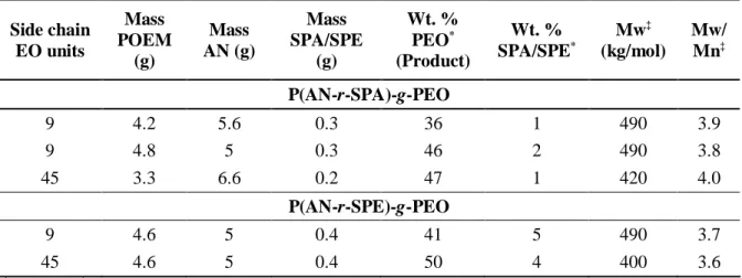
Table 2.2. Monomer composition and purified comb terpolymer product characteristics
Side chain EO units Mass POEM (g) Mass AN (g) Mass SPA/SPE (g) Wt. % PEO* (Product) Wt. % SPA/SPE* Mw‡ (kg/mol) Mw/ Mn‡ P(AN-r-SPA)-g-PEO 9 4.2 5.6 0.3 36 1 490 3.9 9 4.8 5 0.3 46 2 490 3.8 45 3.3 6.6 0.2 47 1 420 4.0 P(AN-r-SPE)-g-PEO 9 4.6 5 0.4 41 5 490 3.7 45 4.6 5 0.4 50 4 400 3.6 *1 H NMR; ; ‡ DMF GPC, PMMA standards 2.4.2. Terpolymer Characterization
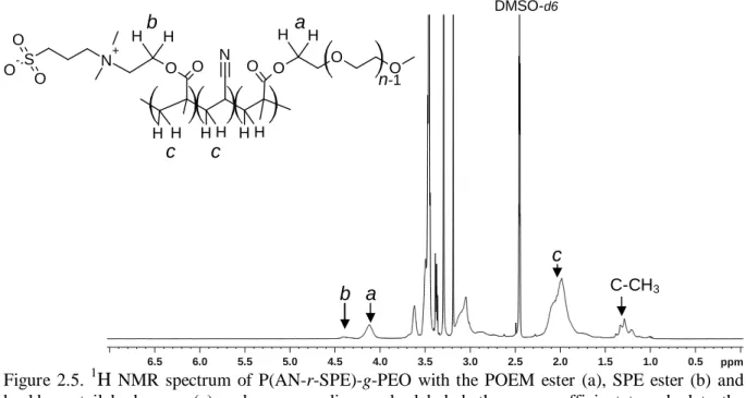
The PEO and SPA/SPE content of the terpolymer combs were determined by 1H nuclear magnetic resonance (NMR) spectroscopy with a Bruker DPX 400 spectrometer (Figure 2.5). The peak for the ester (COOCH2) protons of the SPE moiety is more highly shifted (4.4 ppm) than for the POEM ester (4.1 ppm). Together with the integration of the broad peak representing the backbone tail protons (1.7-2.2 ppm), the PEO content and SPE content can be calculated. PEO side chain length can be calculated from the ratio of the PEO peaks (Figure
2.3) to the PEO ester peak, subtracting the known contribution due to the SPE tether protons. The SPA ester proton peak overlays that of the POEM ester protons (spectrum not shown, but qualitatively equal to that of PAN-g-PEO (Figure 2.3)), so the integration of the methacrylate (C-H3) proton peak is used to disambiguate the contribution of SPA and POEM to that peak. The molecular weight was measured by GPC (2.2.2). These properties are reported in Table 2.2.
Figure 2.5. 1H NMR spectrum of P(AN-r-SPE)-g-PEO with the POEM ester (a), SPE ester (b) and backbone tail hydrogens (c) and corresponding peaks labeled; these are sufficient to calculate the content of both PEO and SPE.
2.5. Membrane coating
2.5.1. Coating Method
Solutions of each polymer were prepared by dissolving 1 g dry polymer in 4 ml DMSO (Figure 2.6). For membranes fabricated with PEG additive, ~4 wt. % PEG9, PEG23, or PEG45 was added to the solution of the respective PAN-g-PEOn comb (a concentration of 10 wt. % within the ~40 wt. % PEO domain of the combs). The solutions were filtered through a 1 µm glass syringe filter (Whatman) and degassed at 70 °C for approximately 1 h. A 12x30 cm section of PAN-400 membrane was fixed to the coater (Testing Machines, Inc., Ronkonkoma, NY) and the doctor blade was set to 30 µm height and fixed to the motorized
N+ S O O O- O O N O O O O H H H H H H H H H H 6.5 6.0 5.5 5.0 4.5 4.0 3.5 3.0 2.5 2.0 1.5 1.0 0.5 ppm a a b b c c c C-CH3 DMSO-d6 n-1