A Complete MEMS Analysis System and Implementation
byXudong Tang
Submitted to the Department of Electrical Engineering and Computer Science in partial fulfillment of the requirements for the degree of
Master of Science in Electrical Engineering and Computer Science
at the
Massachusetts Institute of Technology
May 2000
@ Massachusetts Institute of Teconology 2009. All Rights Reserved.
A u th o r...
Department of Electrical Engineering and Computer Science
May 8, 2000
Certified by ...
Professor of
Department of Electrical Engineering
Donald E. Troxel Electrical Engineering and Computer Science Thesis Supervisor
A ccepted by ... ...
Arthur C. Smith Chairman, Department Committee on Graduate Theses
ENG
MASSACHUSETTS INSTITUTE
OF TECHNOLOGY
A Complete MEMS Analysis System and Implementation
by
Xudong Tang
Submitted to the Department of Electrical Engineering and Computer Science in May 2000, in partial fulfillment of the requirements for the degree of
Master of Science in Electrical Engineering and Computer Science at the
Massachusetts Institute of Technology
Abstract
The testing and analysis of MEMS (micro electromechanical) devices are two of the main steps in designing MEMS devices. These tasks must be implemented in a way which allows them to be done remotely and by multiple users to form the whole distributed environment to a cooperative work environment. There have been programs that control different hardware, such as stage, pifoc, strobe, etc, but the implementation is local only. Problems such as how to integrate hardware controls to our Java based MEMS client/server analysis system efficiently, especially how to solve some new problem caused by remote operations (such as slowness in focusing, lack of synchrony in the user interface's button press and the process at server side or so) and how to transfer our client/server to the most popular Web server, Apache to gain more efficiency (including future software modification efficiency) will also be solved in the project. In the project, we will strive for seamless integration and interoperation and implement some particular methods to increase the performance of remote hardware control.
Thesis Supervisor: Donald E. Troxel, Title: Professor of Electrical Engineering
Acknowledgements
There are many people deserve my thanks. I only can list some of them here.
I would like to thank Professor Donald Troxel for providing me with the research assistantship that has funded my graduate study at MIT. He has provided valuable feedback and insights as an advisor. Especially, he is always very patient to point out my written errors in English in my memos and thesis to stretch out my English. I would also like to thank Michael McIlrath for many informal meetings for technique questions on Apache, Java and Linux.
I would like to thank my officemates, Danny Seth and Syed for providing a friendly environment for work. Danny and I always are good partners to cooperate to solve some problems in research. Many thanks to Francis Doughty. He always is willing to help us to find some former documents for the project.
I would like to thank my former research advisor Dr. Nat. Durlach, he treat me so nice and kind. Finally, an extra big thank goes to my parents, my sisters. Without their encouragement, I cannot come to MIT.
This work was supported by the Defense Advanced Research Project Agency under contract F30602-97-2-0106
Table of Contents
I
Introduction 81 .1 M M S ... 8
1.2 Computer Microvision... 8
1.3 Components of a Microvision System... 8
1.4 R elev an t W o rk ... 9
1.5 T h esis S tatem en t...9
1.7 O rganization of T hesis...10
2 System Integration 11 2.1 Introduction of MEMS Analysis System's components... 11
2.1.1 MEMS Analysis System Structure... 11
2.1.2 Why we use Java and some integration problems we should solve for our system... 11
2.1.3 Client/Server Environment... 12
2 .2 In teg ratio n ... 13
2 .3 G o als for in tegration ... 13
2 .4 S ystem in tegration ... 14
2.4.1 Integrate a Java Function...15
2.4.2 Integrate C/C++ or assembly source code... 16
2.4.3 Integrate an executable file to MEMS Java Servlet... 19
3 System Performance Enhancement 24 3.1 Some problems which must be considered to speed up remote control/data acquisition...24
3.2 Auto focus a camera and auto adjust the view field of the camera... 24
3.3 Image processing algorithms for controlling the camera... 25
3.3.1 Image processing algorithms for adjusting the view field... 30
3.3.2 Image processing algorithms for focusing the camera ... 32
3.3.2 Procedure for the camera control... 35
3.4 A command line mode to control the pifoc which is error free and error tolerant... 35
3.6 Use signed applet technology...37
3.6.1 Several ways to sign applets... 37
3 .6 .2 A n ex am p le ... 3 8 4 System secure mode 41 4.1 Introduction of security...41
4.2 A complete system security model for MEMS chip remote analysis system...43
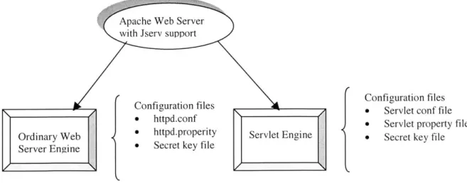
4 .2 .1 S ecu re clien t...4 4 4 .2 .2 S ecu re serv er...4 5 5 Transfer to Apache Web server 48 5.1 Apache Server with Jserv support... 48
5.2 Steps to transfer to Apache server... 49
5.2.1 Introductions to statically build Apache Jserv module for Apache... 49
5.2.2 Introductions to build Apache Jserv as a Dynamic Shared Object... 50
5.2.3 Configuration for Apache server and Jserv... 51
5.2.4 M odify som e source codes of client/server components... 53
5.2.5 Configure MEMS remote analysis system's client/server components...54
5.3 Secure Model fulfilled for our MEMS remote analysis and test system... 54
5 .3 .1 IP filterin g ... 5 4 5.3.2 Connection authentication... 55
5.3.2 Internal security...56
6 Conclusion and Discussion 57 6 .1 C o n c lu sio n ... 5 7 6 .2 F u tu re w o rk ... 57
7 References 60
Appendix B: Some source code 62
1. C code for control Pifoc...62
2. Instruction set for Z-axis Control... 68
3. M atlab program for analysis auto focus algorithm s...70
4. Configure Apache for load balance... 74
List of Figures
Figure 2.1 M E M S A nalysis System ... 11
Figure 2.2 Client/Server Structure for MEMS Analysis System... 14
Figure 2.3 The integration graph for MEMS analysis application system...15
Figure 3.1 Images taken in different z positions... 25
Figure 3.2 Images taken in different z positions... 26
Figure 3.3 Projection of an image on vertical and horizontal direction...26
Figure 3.4 A black-white image ... 27
Figure 3.5 A H igh P ass Filter ... 27
Figure 3.6 The images in figure 3.1 processed by a HIPF... 28
Figure 3.7 The images in figure 3.2 processed by a HPF... 28
Figure 3.8 The relationship of the sharpness evaluation and Z... 29
Figure 3.9 Selected evaluation regions for quicker algorithms...33
Figure 3.10 The flow chart for control a camera...35
F igure 4.1 S ystem secure m odel...46
Figure 4.2 Clinet/Server authentication...47
Chapter 1
1 Introduction
1.1 MEMS
MEMS are micro electromechanical devices incorporating small devices that react to electronic stimuli in a mechanical way. MEMS chips and VLSI chips are produced and manufactured using similar techniques. MEMS are laid out and packaged within a chip that looks similar to an electronic microchip. The main difference is that MEMS chips use small machines in addition to electronic circuits in the chip. The mechanical devices in MEMS chips move and tilt. As a result, the machines placed in the MEMS chip must be developed and tested for response and durability. That is where computer microvision arises as a good tool to use for analysis during the testing and development stages of the devices.
1.2 Computer Microvision
Computer microvision consists of a microscope device for data acquisition and a computer system for data analysis and hardware control. Computer microvision may be utilized in the analysis and development of MEMS.
1.3 Components of a Microvision System
The components of a computer microvision system consist of a device that allows magnification of an object under study, a computer to implement control and data processing, and a device that can collect and transmit visual data. These components imply, as is the case with the present applications, that the device or object under study is too small for direct observation. Thus, in order to observe the object, or some aspect of it, the visual data collector must be able to sense the object with some minimal amount of accuracy. There has been research to determine a fast and reliable algorithm in order to accomplish precisely this sort of detection at the subpixel level [Zoher].
Finally, the computer is also in control of the stage position of the microscope. As a result, the computer has enough information about the system to aid in the testing process. It has an understanding of what the input signals to the object under test are since it is interfaced with the excitation device. In addition, the computer can determine, to some degree of accuracy, how the
object under test behaves as a result of the specified input, since it has an interface with the camera system. Thus, the desired response to a specific input can be compared to the measured actual response from the MEMS device.
1.4 Relevant Work
The interface and the overall architecture have been defined by several graduate students here at MIT [Carney, Jcottr, Erik] "4. The main differences between that system and the present system being designed and modified are that the old system is not a complete one and some frames for integration are not feasible or not easy to use in Java. Furthermore, the old system never really integrated hardware control, especially some executable code complied from C/C++, so it is impossible to know the real performance of the whole system. Some new problems arise from polling message structure. In the message structure, a client sends his request to the server, and the server responds to the client. If the server has some data ready for the client, the server could not send the data to the client automatically. It has to wait for the client to send a request, "Do you have message for me?" If yes, the server responds to the client's request. In some situations, such as a request to show an online video/image to client, the update rate of the image frame will be quite low. Some new problems arise from threads asynchronies. The old system has multiple threads for multi-users. But there is only one server thread for each user. If a user sends many different kinds of requests from a user interface in a short time .The whole message system will be clogged. A cooperative work environment needs our message system enhanced to support some more complicate situations, such as message can even be delayed a day or an hour to dispatch back to user (such that user A is waiting another user B to provide analysis data to him via the server).
1.5 Thesis Statement
The testing and analysis of MEMS (micro electromechanical) devices are two of the main steps in designing MEMS devices. These tasks must be implemented in a way which allows them to be done remotely and by multiple users to form the whole distributed environment to a cooperative work environment. There have been programs that control different hardware, such as stage, pifoc, strobe, etc., but the implementation is local only. Problems such as how to integrate hardware controls to our Java based MEMS client/server analysis system efficiently, especially how to solve
in the user interface's button press and the process at server side or so), and how to transfer our client/server to the most popular web server, Apache, to gain more efficiency (including future software modification efficiency) will also be solved in the project. In the project, we will strive for seamless integration and interoperation and implement some particular methods to increase the performance of remote hardware control.
1.7 Organization of Thesis
The preceding section presented the overview of MEMS analysis system. Some general problems that must be addressed are given. The next chapter will focus on problems of integrating other software to our Java based Client/Server infrasture. Chapter 3 will describe some methods to improve the performance of the MEMS analysis system. Chapter 4 will discuss the secure considerations. Chapter 5 will show how to transfer MEMS analysis system environment from Java Server to Apache Server. Chapter 6 proposes some future work. Chapter 7 gives conclusion and a final summary.
A detailed reference to the configure/install of the servlets, client programs and hardware control program for MEMS analysis system is included in the Appendices at the back of this thesis.
Chapter 2
System Integration
2.1 Introduction of MEMS Analysis System's Components
2.1.1 MEMS Analysis System Structure
LED + Video g
Pifo + 4LED driver digitizer
--- er Pifoc controller ign alo Centium
Stage drifver
Stage
Figure 2.1 MEMS Analysis System
Figure 2.1 gives the MiEMS Analysis System's structure.
From a software aspect, MEMS Analysis System is a typical distributed software environment. In a few words, it is a distributed analysis environment with a client/server structure. So we want it to be platform independent, have an open structure to integrate other applications, have some kind of data security, have reasonable performance under limited network bandwidth, and to provides application interface standard for interoperability of tools.
MEMS Analysis System is a heterogeneous Client/Server environment. Many specific analysis and design tools are already completed. The internet enables users remote operation of a camera, stage and other analysis hardware. In order that users can analyze the system in a cooperative way, the system should support seamlesss integration and some kind of interoperation.
2.1.2 Why we use Java and some integration problems we should solve for our
system
Java based client-server technology can be seamlessly integrated with the WWW. A web browser and a web server is a good Client/Server structure. It is object oriented, platform independent, and
Some problems which need to be solved include:
" Applet download from server cannot access local files and devices. " Sometimes, Java code is too slow to fit our requirements.
" Integration of other modules developed by other language.
* The security of the system. Internet application is subjected to various attack, such as IP sniff, IP hijack, IP Spoof, Trojan Horse, DNS faker.
0 The stateless nature of the HTTP protocol and the lack of communication between the web browser and the Java web server cause some problems.
Possible servers for our system are Java Web Server or Apache Web Server. On the client side, Navigator, IE, Appletviewer or Hotjava are possible choices. But the Apache and Netscape combination is guaranteed to be supported by our system.
2.1.3 Client/Server Environment
In order to integrate analysis tools in Linux or Unix operating system, hardware control tools programed by C/C++, the implementation of the system should be platform independent and should also allow for expansion. One of the best languages to accomplish these tasks is Java, which has the capability of creating graphical user interfaces and can be run on any browser that supports Java. Since nearly all operating systems have some kind of browser, our system can be run on most platforms.
Figure 2.2 shows Client/Server Structure for MEMS Analysis System.
Before the introduction of the interaction procedure, some simple explanation of to some terms is necessary. Applets are Java programs downloaded from a web server and run in a web browser. Servlets are platform-independent server side components, written in Java, which dynamically extend the Java-enabled server. They provide a general framework for services built using the request-response paradigm. Their initial use is to provide secure web-based access to data which is presented using HTML web pages, interactively viewing or modifying that data using dynamic web page generation techniques. Servlets are usually are dynamically loaded (of course, a web server can be configured to force loading and initializing particular servlets when the web server is started up).
All the programs for the client and server are located on our server side. Client, may use various kinds of web browsers to access our system via URL of our server. Users specify a URL like
http: / /stage.mit. edu: 8080/UT to connect to the server named 'stage'. 8080 is the port number
of the web server. After that, the applet stored in the server side is transferred to the client side where the applet starts up a login interface. After login, a user can choose one GUI interface from a list of GUI interfaces. Then the user gets the script file (a kind of setting file for GUI) from the
server, and starts a GUI in the client side. The user can use tools in the GUI to acquire data or request other service from the server. From a software aspect, the server actually uses servlets to respond to requests from the client. According to different kinds of requests, servlets call some internal objects (classes), or some native methods, or just directly execute an executable program to
get data or drive hardware or take a picture.
2.2
Integration
In general, there are some problems which belong to the integration aspect which need to be solved:
(1) Applet downloaded from server cannot access local files and devices, unless it is signed. (2) Sometimes, Java code is too slow to fit user's requirements.
(3) Sometimes, the integration of other modules developed in other languages is necessary. So we need methods in Java code which can:
(1) Integrate a Java Function.
(2) Integrate C/C++ or assembly source code from .obj level.
(3) Integrate Executable program (such as some Windows program or dos *.exe program).
2.3 Goals for integration
(1) Enable write/read file/hardware in server side or client side (2) Enable call an executable files method
I cooperated with another graduate student to integrate these modules to our MEMS analysis system:
Device Excitation, Strobe Generation, Microscope Control
Computer Controlled Microscope, Waveform Generator Control, Camera Control Data Processor and Controller for System, Microvision System
(3) Solve some low efficiency problems caused by call method.
0 Using image processing technique to auto focus a camera, including converting a BMIP image file to a pixel array for processing.
* Solve the delay caused by polling message system.
Device I Device n Data Base Gee)@
Data service Message process Hardware Control
MEMS Servlets
Apache 1.3.9 Web Server/Java Webserver
Web Web Web
Browser Browser Browser Client I Client 2 0GQ Client n
Figure 2.2 Client/Server Structure for MEMS Analysis System
Integration problems will be faced in those situations:
* when an application cannot be written entirely in Java. The standard Java class library may not support the platform-dependent features needed by the application.
* You may already have a library or application written in another programming language and you wish to make it accessible to Java applications.
* You may want to implement a small portion of time-critical code in a lower-level programming language, such as assembly, and then have your Java application call these functions.
In Figure 2.3, The integration graph for MIEMS analysis application system is given. From it, we know most integration tasks are focused on server side's servlets implementation. Servlets are written in Java and can call other C/C++ executable code and .obj module or Java code.
MEMS Server
Servlet HTML CGI
(Java Code)
IC++ /batch file .O(in Linux)JaaApe
Executable) OBJ(in NT) OJava ppe
Figure 2.3 The integration graph for MEMS analysis application system
Now I will give details on how to integrate these components to our system.
2.4.1 Integrate a Java Function
This is rather direct.
1) Add a Button (or Menu or Icon) to interface.
Change setting files your-settingjile. txt
In FunctionHandler.java in handlePrimitiveFunction module add a line to process
message
3) Add the function that responds to the button
In FunctionHandler.java add the function that responds to the button event
2.4.2
Integrate C/C++ or assembly source code
1. Integrated as DLL
1) Create a Java class that declares the native method. It also includes a main method which calls the native method.
2) Compile the Java class that declares the native method and the main method.
Javac J123.java
3) Generate a header file for the native method using javah with the native interface flag -jni.
Javah -jni J123
4) Warp program written C or C++ to JNIC format.
5) Compile the header and implementation files into a shared library file, a DLL.
6) Now you can run the Java program.
Below are example files:
--- J 123.java---/ the class name is the same as the file name
// class J123 call a native method programmed by C
class J123
{
public native void displayHelloWorldo;
static
{
System.loadLibrary("hello"); }
I
public static void main(String[] args)
{
new J123().displayHelloWorldo; }
--- automatically generated header file
/ this file is automatic generated by Javah -jni J123 #include <jni.h>
/* Header for class J123 */
#ifndef _Included_J 123 #define _IncludedJ123 #ifdef _cplusplus extem "C"
{
#endif /* * Class: J123 * Method: displayHelloWorld * Signature: OV */JNIEXPORT void JNICALL Java_J123_displayHelloWorld
(JNIEnv *, jobject); #ifdef _cplusplus I #endif #endif --- JNIC:
try.c---/ the C program implement the method used by Java program
#include <jni.h> #include "j 123.h" #include <stdio.h> #include <process.h>
JNIEXPORT void JNICALL
Java_J123_displayHelloWorld(JNEnv *env, jobject obj)
{
char s[80];
printf("This is a program run from Java\n"); printf("Java call JINI C\n");
printf("please input command line:\n"); gets(s);
system(s); return; }
2. Integrate an executable program (such as some windows program or dos *.exe program) This can be solved by using steps similar to those above.
---JNIC: warp.c ---#include <jni.h>
#include "j 123.h" #include <stdio.h> #include <process.h>
JNIEXPORT void JNICALL
Java_J123_displayHelloWorld(JNIEnv *env, jobject obj)
{
system("Executablefilename"); return;
}
Or directly use RunExec method in Java to call an executable file (.exe .bat in Windows NT or a shell file or other executable file in Linux /Unix). In 2.3.5, more detail will be given on the RunExec method for integration.
Some discussion for integration
1) How to exchange data between these Java module, C/C++function, .EXE modules
(1) file
This is versatile, but slow, and the format is not easy to control.
(2) command line
Using ArgC, Argv is simeple and quick.
(3). variables of environment
This is quick, versatile, but has some limitations, in that Java applet can't access the environment for security reasons.
To get a value from the current environment, call getenvo; char *getenv( const char *varname);
Return Value:
Each of these functions returns a pointer to the environment table entry containing varname. It is not safe to modify the value of the environment variable using the returned pointer. Use the _putenv function to modify the value of an environment variable. The return value is NULL if varname is not found in the environment table.
Parameter:
varname Environment variable name Remarks:
The getenv function searches the list of environment variables for varname. getenv is not case sensitive in Windows NT and Windows 95. getenv and _putenv use the copy of the environment pointed to by the global variable _environ to access the environment. getenv operates only on the data structures accessible to the run-time library and not on the environment "segment" created for the process by the operating system. Therefore, programs that use the envp argument to main or wmain may retrieve invalid information.
Java programs cannot read environment variables the way that native programs can. The reason is that environment variables are platform dependent. Similar mechanisms exist, however, that allow applications to read the value of a named resources, called system properties list.
(4). Java objects (array, string, etc)
With the JNI framework mentioned above, both the native language side and the Java side of an application can create, update, and access Java objects and then share these objects between them.
2) Integrate Java to C/C++
Native methods written in C/C++ can also easily call Java methods. Often, you will already have developed a library of Java methods. Your native method can directly perform the functionality already incorporated in existing Java methods. The native method, using the JNI framework, can call the existing Java method, pass it the required parameters, and get the results back when the method completes.
2.4.3. Integrate an executable file to MEMS Java Servlet
Note: all finished classes should be put on server side. Step1 Create the set file for a user interface.
For example, trysetting.txt in Mems' D:\JavaWebServerl 1. 1\public-html\guiSettings Several example files are in this directory ( please refer to Erikp's thesis"4])
mainFrame = Frame("Control Stage"); // Create a Frame object, name is mainFrame, / title is "Control Stage"
mainMenuBar = MenuBar("Main MenuBar", mainFrame); // add menu object in the frame object control = Menu("Control", mainMenuBar); // add menu item in the menu object
takeControl = Menultem("Take Control", control, takeControl()); // do same thing as above cedeControl = Menultem("Cede Control", control, cedeControl());
checkControl = Menultem("Check Control State", control, checkControl()); reset = Menultem("Reset Server", control, reseto);
shutdown = Menultem("Shutdown Server", control, shutdowno);
mainPanels = PanelFrame("Main Panels", mainFrame, 1, 1); / create a Panel Frame in the frame object /for putting buttons
sizeSettingsPanel = Panel("Try Panel", mainPanels); // create a panel in the Panel Frame tryme = Button("trymedemo", sizeSettingsPanel, try-meo); // create a button in the panel
Step2 modify client Java program
Modify GUI stuff----FunctionHandler class in the directory
D:\erikp\java\FunctionHandler\ then compile it and put FunctionHandler.clas to Mems's D:\JavaWebServer].1. ]\publichtml\UI\FunctionHandler
so that all requests from the User interface are processed. Add the message, which is sent out by the user interface and is sent to the MIEMS Java Servlet.
(1) Add the processing in handlePrimitiveFunction class to process the task launched by the button
private void handlePrimitiveFunction(String wholePrimitiveFunction)
StringTokenizer st = new StringTokenizer(wholePrimitiveFunction, "(", false); String primitiveFunction = st.nextTokeno;
if (..
else if (primitiveFunction.equals("try-me") trymeo);
// process the primitive function . The first try me is message from user interface. // The second try me is funtion call which processing the message. They are not
// necessary to have the same name
}
(2) Provide the function which will get the service from the servlet
For example:
Type 1 call send message from other Module
private void try-me()
{
String controlState = hardwareControlModule.checkControlStateo; if (controlState.equals("ACTIVE"))
Globals.xTranslation = Integer.toString(Integer.parseInt(Globals.xTranslation) + 0); hardwareControlModule.setStageo; //Here directly call an existed funtion which
// will send message to the servlet else if (!controlState.equals("ACTIVE"))
JOptionPane.showMessageDialog(null, "You do not have control of server", "Information", JOptionPane.INFORMATIONMESSAGE);
We can directly send out message here or call a function that will send a message which are in the same directory with FunctionHandler.
Type2 directly send message
private void try-me()
String sessionID;
sessionlD = String.valueOf(Globals.sessionID);
NVPair[] message = MessageDatabase.get("TRY-ME"); message[ 1].setValue(sessionlD);
/* if you want to send some parameters here
you can do like this
message [2].setValue(Globals.strobeFrequency); message[3] .setValue(Globals.divisions); message[4 .setValue(Globals.phase);
*/
Hashtable responseH = sendMessage(message);
String command = (String)responseH.get("COMMAND"); String msg = (String)responseH.get("MESSAGE"); if (command.equals("ACK"))
{I
else if (!command.equals("ACK")) // error(responseH);
(3) Add the message definition in MessageDatabase class. in D:\erikpjava\MessageDatabase Finally, update the MessageDatabase class in Mems' D:\JavaWebServerl.J.1\public_html\ UI\MessageDatabase\
//Add a new message for a new function NVPair[] tryme = new NVPair[2];
tryme[0] = new NVPair("COMMAND", "TRY-ME"); try-me[l] = new NVPair("SESSION-ID","");
Step3 modify server side program
(1) Register new message which will be handled----Modify MessageServlet.java at D:\jared\thesis
then copy .class file to Mems' D:JavaWebServer].].1\servlets void initMessageCenter( HardwareControl hc,
DataProcessingEngine dpe, Database db)
{
// add a register line.
messageCtr.registerHandler(new trymeHandlero);
}
(2)Provide a message handler for the new message in the directory of D:\jared\thesis\MEMServer\messaging\HANDLER\ and save it to Mems' D:\VavaWebServer].1. ]\servlets\edu\nit\MEMServer\nessaging\Handler\ YOUR_HANDLERFILE For example, package edu.mit.MEMServer.messaging.handler; import java.io.*; import edu.mit.MEMServer.messaging.*; import edu.mit.MEMServer.data.*; import java.util.Hashtable; import java.lang.Runtime import java.util.Vector;
public class try-meHandler extends MessageHandler { public try-meHandler ()
commandName = "TRY-ME"; //to define the message handler process which
/message
// below check if the message format is correct
public boolean isValidMessage (Message m) if ( !m.isValid( )
return false;
if ( !m.getFieldValue(new String("COMMAND")).equals(commandName)) return false;
if ( m.getFieldValue(new String("SESSION-ID")) != null) return false;
public Message handle ( Message m ) { SessionList sl = ss.getSessionListo;
String newSessionlD = sl.startSessiono; Hashtable h = new Hashtableo;
h.put
new String("COMMAND"), new String("ACK")
); //send out ACK to client
h.put
new String("SESSION-ID"), newSessionlD
); // send out session ID
h.put
new String("MESSAGE"), commandName
); // send out the comand which is processed by the servlet
try { // call executiable file
// set up command, arguments, and environment variables String[] envp = new String[ 1];
String prog = "stage 2";// the program(with parameters) which will be called by // JAVA the executiable things can be a shell comand,
// suca as String prog = // "Ibin/ls" in Unix/Linux; Runtime rt = Runtime.getRuntime(;
Process pl = rt.exec(prog); //'/bin/ls' or 'stage 2' } catch (IOException e) {}
catch(SecurityException e){ }
return new Message(h);
Step4 create server side program
Create an executable program named stage, which is called by the new handler
Note:
All above steps are the most complete version. Some steps are not necessary for some particular cases.
Chapter 3
System Performance Enhancement
3.1 Some problems which must be considered to speed up remote control/data
acquisition
There are several aspects to improve the performance of our MEMS remote analysis system. (1) Speed up some time critical missions. Such as use more efficient algorithms, use quicker program language, change some manual operations to automatic operations, etc.
(2) Provide a client/server infrasture with higher performance. Such as server response user with multi-threads. Even response the same user's different requests with multi-threads.
(3) Provide a friend interface for use to access some services. So that the system overall performance can be increased dramatically by error prevention and error tolerance.
3.2 Auto focus a camera and auto adjust the view field of the camera
In the old MEMS analysis system, camera focus operation is manually done locally via observing the image on a monitor. The focus speed is fast. Now we want to remotely manipulate the stage and pifoc to focus the camera and adjust view field and user can quickly choose the region of interested of an image. Because of the band limit of the network, it is very slow to take a lot of pictures, then transfer them to the client side for the user to evaluate if the picture is in focus and in a good view field. The processing entails taking pictures then sending them to the user interface via network, after that, adjusting the camera from user interface, then take the new picture and send to user interface again via network. We iterate the process until the camera begins to send clear and correctly size pictures so then we can say the camera is in focus and is ready. All this processing is very slow. Especially, we test and find move stage in x, y axis is extremely slow and move in z axis is not as slow as in x, y axis . So it is necessary for us to use image processing technology to automate the server processing in our client/server environment. We know the picture in focus is sharper and has more high frequency components. We can design a HPF (high pass filter) to evaluate whether the picture is in focus. If we want to let a MEMS chip fully occupy the view field of the camera, we need to use image processing technology to separate foreground from background, or find a way to know where is the position on an object(a MEMS chip).
3.3 Image pocessing algorithms for controlling the camera
In order to automate above tasks: Auto focus, auto move picture in a good view field and quickly control stage to let image is exposure in the region of interest. Several tasks should be solved first. (1) Transfer BMP format picture to pixel image array.
So that we can process the image with 2-Dimensional filter. In Linux, there are no .bmp files used. This step can be neglected.
(2 ) Process the pixel image array with filter to evaluate whether the image is in focus or not. (3) Find method to evaluate the picture position and try to move it to correct position.
So that the image's center is in the middle of view field. (4) Responds user's request to set the region of interest
Currently there is no requirement to set view field to the region of interest. Only use it to analyze the motion of interest region. So this is part of work of design a GUI actually. I have finished it.
Figure 3.1
Figure 3.1 shows images taken in different z positions, the first one is taken in focus position, The other 3 taken with z move with +100 micron, +500 micron, +1000 micron.
image.bmp 640X480
image-500.bmp 640X480 image-1 000.bmp 640 X480
Figure 3.2 (Above) Figure 3.3 (Below)
6 5 4.5 4 3.5 3 0 4 2-D image, size: 640X480 11 0 200 400 600
Projection of 2-D image on X axis
10
Pr
100 200 300 400 ojection of 2-D image on V axis
800
/
I-5 4 3 2~v\I
500250 200 150 100 50 n
image mapped from orignaJ 0 Projection 100 of 200 2-D image on 300 400V axis
200 400 600 600
Projection of 2-D image on X axis
Figure 3.4 (Above) Figure 3.5 (Below)
The impulse response h(nl 1n2) of a 2-D High Pass Filter
10 C C -c 5 I --'1~ - I -Le- 2-- '- I 2 n1 3 1 n2 500 150 100 50 0' 0 3 0 1
100 200 300 400 100 200 300 400 100 200 300 400 500 600 image0 processed by HPF 100 200 300 400 500 600 image+500 processed by HPF 100 200 300 400 500 600 imae+1000 processed by HPF
Figure 3.6(Above) Figure 3.7(Below)
100 200 300 400 500 600 image processed by HPF 100 200 300 400 100 200 300 400 :4 14 100 200 300 400 500 600 image -100 processed by HPF 100 200 300 400 500 600 image -1000 processed by HPF 100 200 300 400 100 200 300 400 100 200 300 I 400 100 200 300 400 500 image-500 processed by HPF
x 10 1.8 E CD (-n CO E CO, CfJ CO, CO' 1 78 -76 -1.74
I-1 1 .72 k 1.7 68 -1.66 2 3 4z position sample index
6
1 7
Figure 3.8 The relationship of evaluated shparpness-z position
Figure 3.2 shows images taken in different z positions, the first one is taken in focus position, The other 3 taken with z move with -100 micron, -500 micron, -1000 micron.
Figure 3.3 shows projection of image.tif (or .bmp format) on vertical and horizonital. Note, x, y axis is defined as below:
0 1 X
Y
Figure 3.4 shows a black-white image which is process by a noise elimination algorithm and converted to black-white. Its vertical and horizontal projections are shown in the figure too. Figure 3.5 given a HPF(High Pass Filter).
1 -3 1 H[ni,n2]= -3 9 -3 7 7 / 7 (
/
/ / / I --Figure 3.6 shows the images shown in figure 3.1 processed by the HPF in figure 3.5 Figure 3.7 shows the images shown in figure 3.2 processed by the HPF in figure 3.5
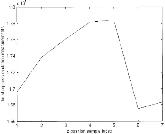
Figure 3.8 shows the sharpness evaluation measurement for different images taken in different z position.
Index of z correspond images sharpness evaluation measurement
1 image-1000 169616 2 image-500 173858 3 image-100 176110 4 image0 178149 5 image+100 178431 6 image+500 167538 7 image+1000 168329
3.3.1 Image processing algorithms for adjusting the view field
1 Algorithm
The algorithm is for moving an image from a biased position to the center of the view field.
I find a way to evaluate the position of the picture-use projections of the picture on vertical and horizontal directions. The region without the object will have much less energy, and the projection will be much low. Please refer to Figure 3.3. The projection between 0-100 pixels on Y axis(corresponds image's up region) is low. So there is no MEMS chips in this region. So we need move the view filed down ward 100 pixels, which equals to move the object upward 100 pixels. But as we can see from Figure 3.1 and Figure 3.2, the background noise is big. There is obvious a big bright spot in the image, which is caused by refection of the light by the surface of the platform which is used for put MIEMS chips.
2 An enhanced Algorithm with noise eliminated
We find the characteristic of the refection has a mirror effect. All refection is strong and has nearly the equal brightness. While an object (MEMS chips) in the picture has varied brightness and irregular illumination. According to this characteristic, an enhanced Algorithm with noise eliminated given as the below:
Assuming the image is saved in a pixel array hO(ij);
n is height, m is width. The average gray scale for the picture is set as 75. The detection a mirror effect threshold is set as 15. The idea of the algorithms is if we find more the 15 continue bright pixels then we assert that it is in mirror effect region-the spot of light. If the spot of light location overlap with an object. It doesn't matter. At the same time, the algorithms convert the gray scale image to a binary black-white image. So each bright pixel has the same projection weight-not
associate to its grayscale.
% algorithms written in MATLAB
AverageGrayScale=75; Mirror_effect_length=15;
n=480; m=640; // picture size, n is height, m is width
for i = 1:n, count=O; for j = 1:m, if hO (i, i ) > AverageGrayScale A(i, j )=1; count=count+1; if count>; Mirroreffectlength for k=begin:j A(i,k)=O;
end count=O; end else A(i,j) =0; begin=j; end end end subplot (2, 2, 3); hO_x=sum(A,1); plot (hOx);
xlabel('Project of 2-D image on X axis'); subplot(2,2,2);
hOy=sum(A,2); plot(hO y);
Above algorithms can be optimized further to eliminate the spot of light. But above algorithms is enough for our to evaluate the position of the picture.
The average gray scale is used as threshold for converting an image. Although this is an estimated values. But it is accurate enough for our purpose of detect the position of the image. And furthermore, it save our calculation time. The average gray scale is not sensitive to different kinds of MEMS chips.
Please refer to Figure 3.4. The enhanced algorithm works very well. It can detect 0-180 (in pixels) region has no object. Compared to Figure 3.3 which uses the original algorithm, only detects 0-100 region no object.
3.3.2 Algorithms for focusing the camera
1 HPF design
We want integer coefficients for the HPF so that the convolution computing is fast. Second, the sum of all amplitudes of impulse response is one, so that the filter frequency response H(wi ,C 2) is one at oi=O2=0 and pass all the DC components unaltered. This character has the effect of keep the average density of original image in the processed image. By the way, because background noise typically has high frequency components. HPF tends to increase the background noise. Some time, if necessary, we can use median filter to eliminate pepper-salt noise. But the picture quality from our camera is rather good. It is not necessary to apply a median filter on the image.
2 Algorithms
First convolution the HPF's impulse response with the image. Then use the evaluation algorithm to get the image sharpness evaluation measurement.
The evaluation algorithm is rather direct, first get the pixel's average brightness, then count the number of dark points which are darker than the average brightness as the image sharpness evaluation measurement.
The Algorithm is defined as function GetCurrentPositionlmageEvaluationo; In the next algorithm we will use the function.
% Process image by t HPF
hdl=[1 -3 1; -3 9 -3; 1 -3 1];
h_O=conv2 (hd1,hO); subplot(2,2,1); image(h_0);
%Lmshow (hO)
xlabel('imageO processed by HPF');
% below show the each picture's evaluation measurements
n=480; m=640; countl=G; Pixel-average=mean(mean(h_6)); for i = 1:n, for j = 1:m, if h_6(i,j) < Pixelaverage countl=countl+l; end end end count1
3 Problems and soloution
Problem 1: Speed
The above algorithm is not bad, because there is no calculation of frequency components. Only there is a nine points convolution with a 640*480 array. Cost is about 9*642*482= 2.78* 106 times,
about 8*642*482= 2.48*106 adds.
But we can get a much quicker algorithm. The idea is to evaluate only part of the image, not the whole image. Just like some auto focus cameras in today market, we can use one sample region, three sample regions or five sample region to get the camera sharpness evaluation measurement.
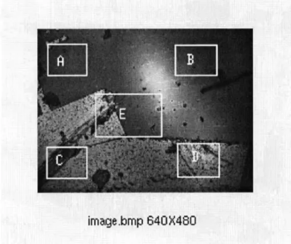
Figure 3.9 Selected evaluation regions for quicker evaluation algorithms
Figure 3.9 givens 5 selected evaluation regions for quicker evaluation algorithms. We can use only E region or combined A,B,C,D,E one or more regions to get the evaluated sharpness measurement
of an image. If we use only 1/16 area of an image with 640*480, that is to say, use 160*120 that is still big enough and is accurate enough to evaluate the sharpness of an image. While calculation time will decrease to 1/16 of original calculation time!
Problem2: Evaluated sharpness measurement to z is not strictly changed monotonically
Please refer to Figure 3.8, we can find the evaluated sharpness measurement to z is nearly changed monotonically when search from one side (left or right side of peek point) for maximum. But not strict. Some time affected by noise will cause some variant curve. But the magnitude for the variant is small. So when search for the focus, the maximum point by change z, we need use a threshold to control the search procedure. We find threshold = 500 is good enough for the z movement step =
100 micron and the image size 640*480. By the way, in the experiment we find 100 micron as step is good enough to get a clear picture. For more accurate focus, we can use the same algorithm with different threshold to get the optimal result. Algorithm for the optimal z, the focus point is as below:
Threshold=500; Zstep=100;
FlagIncreaseZ= 1; Searchbacktimes=O;
OldEluationMeasurement= GetCurrentPositionImageEvaluation);
Note: The is algorithm mentioned in (2)
Loop :
move z a step with Z-step*FlagIncreaseZ
NewEluationMeasurement= GetCurrentPositionImageEvaluation(); If ((NewEluationMeasurement- OldEluationMeasurement)>Threshold
{
FlagIncreaseZ = Flag_IncreaseZ; // means keep search direction.
Try to move z a step with Z-step*FlagIncreaseZ OldEluationMeasurement=NewEluationMeasurement Goto Loop;
}
else
{
FlagIncreaseZ= -FlagIncreaseZ; // means reverse search direction
Searchbacktimes += 1; // rember how many times the same
point evaluated
If(Searchbacktimes>=2) Goto End;
Try to move z a step with Z_step*FlagIncreaseZ OldEluationMeasurement=NewEluationMeasurement Goto Loop;
End:
Move z to the optimized position
If we assume that we can set camera to the minimum z, before we begion auto focus camera. Above algorithm will be much simple. Actually we do have the command to initialize z to minimum.
Threshold=500; Z-step=100;
OldEluationMeasurement= GetCurrentPositionImageEvaluation();
do
{
Increase z one step;
NewEluationMeasurement= GetCurrentPositionImageEvaluation();
if ((NewEluationMeasurement- OldEluationMeasurement) >Threshold
OldEluationMeasurement=NewEluationMeasuremen; else
break; while(l);
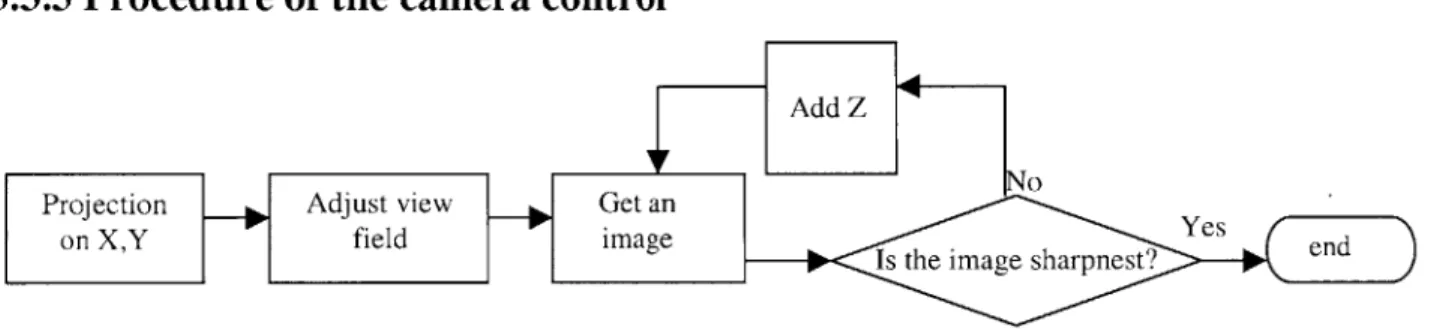
3.3.3 Procedure of the camera control
Add Z
IF No
Projection Adjust view Get an
Yes on XYfieldimageIll.<Is
the image sharpnested
Figure 3.10 Flow chart for control a camera.
Figure 3.10 gives the procedure of controlling a camera.
3.4 A command line mode to control the pifoc which is error free and error
tolerant.
We provide a command line window in user interface for use to control hardware. It is necessary to check the format and the correctness of the command line, so that the user need not wait until the server tells him something is wrong and needs a change of the command. All check work should be done in the client side. So checks done on the server side should be moved to the client side so that we can increase the system's performance. Please reference Appendix B part 2.
1 Command Format
SEND is a program for serial port communication
COMPORT is COM1-COM4
BAUDRATE is 300,600,9600,19200,38400 bits/second COMMAND is one command of the command set. 2 Command Set
Some of the most important commands for the E-662 operation please reference Appendix B part 2.
One typical example is:
SEND COM] 9600 setrem // set control mode to remote control mode SEND COM] 9600 pos 60 / set z-axis position to 60 um
SEND COM] 9600 pos ? // get current position of z axis
3.5
Load balance and other optimization method for the server
Scalability, load-balancing, fault-tolerance are key properties for internet content providers : As the market becomes more mature, the need for static pages web sites decreases, and the dynamic content generation, personalized, and transactional becomes a must. Java is a key technology on the server side, because of its rapid prototyping and validation phases, which give a time-to-market bonus to those who are using it.
However, as the Java Virtual Machines become faster over years, people tend to ask for always more personalized and dynamic contents, and this type of application requires always more and more CPU power. Apache JServ addresses this requirement and lets you distribute your application
load over as many hosts as needed.
Load-balancing includes several levels for Aapche server: Level 0 :
1 host with Apache, 1 host with JServ. The JServ is hosting all servlet zones.
This is the current default mode for Apache JServ (no load-balancing). JServ can be started in automatic mode.
Level 1 :
1 host with Apache, n hosts with JServ. Every JServ is hosting its own servlet zone.This is a possible mode in 1.0 versions. You have to specify one JServ/zone. Apache cannot start the different JServ in automatic mode : you have to set the Manual mode to true.
1 host with Apache, m*n hosts with JServ.
Every zone can have the incoming load distributed on several JServs. You have to use the new "balance" parameters. (see Configuration).
For every zone you have to define a set of JServ hosts that are identical (same servlet classes), and affect a logical weight for every host in that set.
The traffic will be balanced between the JServs in the set, using a simple but efficient algorithm based on host weight + random.
very httpd process (inside one Apache server) will randomly(modulo weight) choose a default target for each zone, and send new requests (sessions not yet created) to this target. The underlying Operating system guaranties (at least on U**xes) that equivalent processes gently share the CPU ressources, and get elected at their turn.
Level 3 :
p*hosts with Apache, m*n hosts with JServ. Same as Level 2, but all our p Apache servers have to use same configuration files to keep sessions alive across all of them (really mandatory: use the
same routing parameters).
Because current our project only use one server , so the load balance is not a real problem. But in the furure, if we want to remotely control a lot of hardware distributed in different sites of Network, this is a very important task for us to finish.
Please reference Appendix B part 4 for a simple example for load balance of Apache server.
3.6 Use signed applet technology
We need to use signed applet technology so that an applet can launch tools in a local machine(such as realplay5.0) or do some read/write operations in the local machine.
But Navigator, IE, and Apache use different formats of certification, how to find a common solution?
Our soloution is ---use Java plugin which is support by most of the browsers. 1) Convert .html files which include 'applet'tag to java plugin's html file.
2) Copy identifydb.obj from JDK home directory and certification generated to java plugin's home directory.
3.6.1 Several ways to sign applets
(1)USE JDK1.1.7B or JDK1.2 " Create a certification " Created a .jar file
" Signed the .jar file by the certification
" Run Sun's HTML Converter to convert the HTML source to enable the Sun Java Plug In (otherwise the Microsoft JVM/Netscape is used and they don't support applets signed by JDK)
(2) Microsoft' tool
" Used Microsoft's MakeCert and Cert2SPC with your X509 certification * Created a cab file
" Signed the cab file " Run the HTML file
(3)Netscape's tool
" Use Netscape's sign tool " Edit Java
. Re-compiled Signed Java
3.6.2 An example Below we use first method: On server side
Steps
1) Package all classes used by the applet to be signed to *.jar file
jar cf jar name.jar *.class YOURDLL.dll YOUEXE.exe 2) Create certification(see below for details)
3) Sign the *.jar file use the certification
javakey -gs sign-specificationjile .jar file
4) Change the .html file which uses the applet, after 'applet' add 'archieve=yourpackagename.jar'
Create certification (l)Create signer
Javakey -cs signerName true
(2)Create Public/Private Key
javakey
-gk signerName DSA 512(3) Generate singer's certification
javakey -gc specification-file
specificationfile include #issuer.name, #issuer.cert, #subject.name #start.date #end.date,#serial.number #out.file,etc
An example of file format introduced later.
On client side
Enable signer--actuall add you to the list of whose x.509 certification you trust
javakey -c subjectName true
Navigator, IE, and apache use different formats of certification,how to find a common soloution? soloution is ---use Java plugin which is supported in most browsers.
1)convert .html files which include 'applet' tag to java plugin's html file.
2)copy identifydb.obj from JDK home directory and the certification just generated to java plugin's home directory.
Preparing:
download Javaplugin, HTML converter when you run your applet, start java plugin
Below is example files for a certification specification file and a sign specification file
===============certspecificationfile================
# the id of the signer
issuer.name=txd
# the cert to use for the signing (this is where it gets it DN)
issuer. cert=1
# the id of the subject
# the components of the X500 name for the subject
subject.real.name=txd
subject.org.unit=JavaSoft subject.org=Sun MicroSystems
subject.country=US
# Various parameters: start and end date for validity and expiration # of the certificate. Serial number. FIle to which to output the # certificate (optional). start.date=1 Dec 1998 end.date=1 Dec 1999 serial.number=1001 out.file=txd.x509 ======================signspecificationfile===============
# Jar signing directive. This is the directive file used by javakey to # sign a jar file.
# Which signer to use. This must be in the system's database. signer=txd
# Cert number to use for this signer. This determines which
# certificate will be included in the PKCS7 block. This is mandatory # and is 1 based.
cert=1
# Cert chain depth of a chain of certificate to include. This is # currently not supported.
chain=0
# The name to give to the signature file and associated signature # block. (i.e. DUKESIGN.SF and DUKESIGN.DSA). This must be 8
# characters or less.
Chapter 4
System secure mode
4.1 Introduction of security
Our system runs in a distributed environment via Internet. Java secure ensures security and robustness in the local environment, especially servlets fully use the Java advantage: memory access violation and strong typing violation are not possible, so that faulty servlets will not crash servers the way that is common in most C language server extension environments. But in a distributed system's security are caused by hacker or some programs with bugs which access resources not intended for them. Possible hacker methods on Internet are:
---IP Hijack ---IP sniffer ---- IP Spoof ---DNS faker
---Trojan Horse(fake a real program)
---not trusted Java applet exposure system private data, change system configuration
Protecting our data from use by other unlicensed people is very important. There are two questions are mostly considered by users for internet applications:
(1) Security of the communication. (2) Data encryption and access control.
A completely secure system includes three facts: according to what you know, such as password and user name; according to what you have, such as electronic certification; or according to your fingerprint and face. Only the first two facts are under consideration in our system.
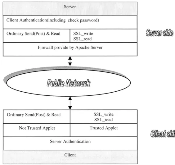
SSL (Secure Socket Layer) is a protocol developed by Netscape for secure transactions across the Web. It is used to enhance HTTP; it is transparent to the browser and the server support telnet, ftp, Mosaic, httpd 1.3, etc. we use Apache 1.3.9 as our Java server and model-ssl as our SSL module. In Apache server, model-ssl is integrated seamlessly into Apache with Extended API(EAPI). We
support authentication both in the client and server, SSLv2, SSLv3 and 128 bits strong cryptography.
Actually there are 3 most popular encryption and user authentication standards for the Web, SSL(Secure Socket Layer), SHTTP(Secure HTTP), Shen.
0 SSL
SSL is proposed by Netscape for HTTP, NNTP, and FTP. It includes Server authentication (verifying server's ID to the client), encreption of data in transit and optional client authentication. SSL is implemented in several browsers, such as Netscape Navigator, Secure Mosaic, Micrsoft IE and many servers, including ones from Netscape, Microsoft, IBM, OpenMarket,etc
0 SHTTP
SHTTP is a higher level protocol proposed by CommerceNet. It only supports HTTP but is potentially more extensible than SSL. Current SHTTP is implemented for OpenMarketplace Server and Secure HTTP Mosaic on Client side.
0 Shen
Shen is a similar to SHTTP, it is a high level replacement for the existing HTTP protocol. No browser or server supports it.
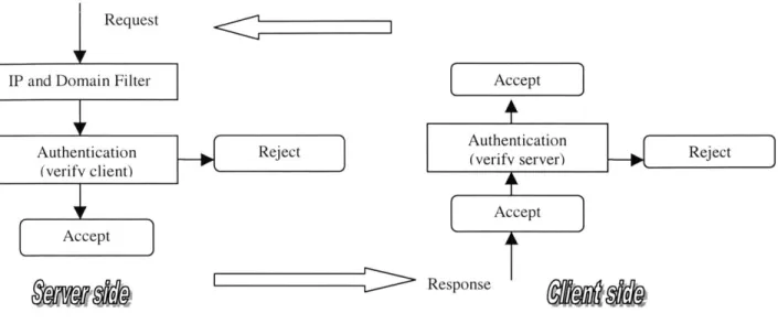
A complete structure of the software for security of C/S interaction includes: (1) Identification and Authentication
We can use user ID and server ID to prevent a fake IP address of client or a fake server. Some enhancement of security for Identification and Authentication:
1)In order to prevent the Hijack of IP, we can design a API to force to check Identification periodically when a connection has been established for some time.
2)Use time stamp to ensure security of the system. Prevent IP/password Sniff. Build a time depend ID lib.
(2) Access Control
There are two kinds of access control
One is Access control to a computer and programs in a computer. Use Java CGI and Window NT server configuration, only special directory and program under special directory can access by remote application, Java applets.
Another is the use of a Multi Level Security Library for client software (which is downloaded from the MEMS server) for enabling and disabling some components and services.
(3) Transit Security
Transit encrypted data on the network.
Encryption is provide by Java API. When we use some Unix based server such as Apache or NCSA httpd and Unix based browsers such as Mosaic, we can use services from SSlayer (it is a free implementation of SSL).
1) Ordinary request
When a client application receives an encrypted response, it decrypts the response according to current time stamps and ID of server to ensure it is correct server (not a faker!).
When a Server gets a request, it does the similar thing as the client.
After a socket between user and server is established, use event driver method to send update information to client.
2) SQL request
DataBase called by JDBC==> Public Network ==> Client ==>decrypt
In order to improve efficiency of Java, during communication for data in database, when data length>5k, we use Zip=====>communicaiton========>Unzip
JDBC have mechanism for check if the caller can access the link too.