Conceptual Design of a Deployable Vehicular Bridge Structure Using
Shape and Geometric Optimization for Post Disaster Relief Applications
by
Diana Estrada
B.S. Civil Engineering
Florida International University, 2015
Submitted to the Department of Civil and Environmental Engineering in Partial Fulfillment of the Requirements for the Degree of
Master of Engineering in Civil and Environmental Engineering at the
MASSACHUSETTS INSTITUTE OF TECHNOLOGY June 2018
C 2018 Massachusetts Institute of Technology. All rights reserved.
Signature of Author:
Certified by:
Accepted by:
Signature redacted
Dep t of Civil and Environmental Engineering
Signature redacted
MASSACHUSETTS INSTITUTE OF TECHNOLOGYJUL 2
6
2018
LIBRARIES
May 1 1th 2 0 1 8 Josephine V. Carstensen Lecturer ofkvil Engineering and Environmental EngineeringSignature redacted
T
hesis
Supervisor
Jesse Kroll Irofessor of Civil and Environmental Engineering Chair, Graduate Program Committee
Conceptual Design of a Deployable Vehicular Bridge Structure Using
Shape and Geometric Optimization for Post Disaster Relief Applications
by
Diana Estrada
Submitted to the Department of Civil and Environmental Engineering on May 11, 2018 in Partial Fulfillment of the
Requirements for the Degree of Master of Engineering in Civil and Environmental Engineering.
In the aftermath of a natural disaster, all efforts are dedicated to a common goal: repairing and bringing the affected communities back to their fully functioning condition. However, it is frequently encountered that infrastructure and roads providing access to these communities are also damaged. As this can slow down the community response time significantly, there exists a need for light, easy to install, and effective temporary infrastructure for immediate restoration of communication.
This thesis presents a new design concept for a deployable bridge structure composed of scissor-like translational units. The proposed structure satisfies the deployment constraints and the stress limits determined by AASHTO LRFD Bridge Design Specifications. The used design approach uses multiple existing deployable geometries and performs a comparative analysis between the different systems. Given the particularity of SLE units, a standard finite element analysis method was enriched to match our conditions and enhance the accuracy of the modeling and analysis. This includes the implementation of master/slave node constraints and zero length rotational springs at the element nodes.
The design problem is formulated as a formal optimization problem with a nested equilibrium condition. Our objective function minimizes the total weight of the structure for a deployable bridge subjected to H15 design loads and stress limits delineated by AASHTO. A design exploration is performed to compare the best designs for different bridge geometries, angles of element inclination and member cross sectional areas. The optimization problem is solved using a genetic algorithm which, at each iteration, uses our beam finite element analysis to check that structural equilibrium is satisfied. Given the potential lack of resources after a natural disaster, providing a light weight extendible structure which would therefore require less force and resources for installation, can have a positive impact in the recovery process.
Thesis Supervisor: Josephine V. Carstensen
Acknowledgements
First and foremost, I would like to express my deepest gratitude to my thesis advisor, Josephine Carstensen. Her excitement, patience and wisdom has guided me not only through this thesis, but also through my time at MIT and professional path.
I would also like to thank our program advisor Gordana Heming for her assistance in helping me
define the focus of my thesis and to Professor Jerome Connor for his guidance and expertise. Next, I would like to express my appreciation for my friends and fellow M. Eng. classmates for
the long work nights and endless encouragement. I am also deeply grateful for all the great people
I have met at MIT, with whom I have created, and continue to create, great memories. Without
their support and help, this thesis would have not been the same.
I would also like to thank my friends and family, near and far.
Most importantly, I would sincerely like to thank my parents for their unconditional support and encouragement to pursue my dreams, no matter what they are.
Table of Contents
Chapter 1 Introduction... 9
1. 1 Introduction ... 9
1.2 Research Objective... 14
Chapter 2 Bridges for Disaster Relief and Basis for Design ... 15
2.1 Existing Types of Deployable Bridge Structures... 15
2.2 Literary Review ... 17
2.3 Proposed Concept Design ... 20
2.4 Scissor Like Elem ent Structures ... 20
Chapter 3 Design. ... 23
3.1 Design Process ... 23
3.2 Design Param eters... 25
Chapter 4 G eom etric Design and Size O ptim ization... 31
4.1 Design Approach... 31
4.2 Geom etric Design... 31
4.3 Shape Optim ization Problem Form ulation... 35
4.4 Optim ization Problem Constraints ... 35
4.5 Optim ization M ethodology ... 39
4.6 Structural Analysis... 40
Chapter 5 Results... 45
5.1 Results ... 45
5.2 Discussion ... 55
Chapter 6 Conclusion ... 59
6.1 Sum m ary of Findings... 59
6.2 Future W ork... 60
List of Figures
Figure 1-Bridge failure by Hurricane Maria in Puerto Rico 2017, leaves communities without
means of evacuation and means of communication for relief efforts [15] ... 10 Figure 2- Hito River Railroad Bridge collapse by flooding and scouring in Japan after Typhoon
N anm adol in 20 12 [16]... 10 Figure 3- Failure of steel truss bridge by Sumatra Earthquake and Tsunami in Indonesia 2004 [8] ... 1 0 Figure 4-Example of a deployable system, an umbrella, used regularly on a day to day basis, in
its deployed and folded state [2]... 11
Figure 5-Classification of deployable structures based on the morphology and kinematic
ch aracteristics [10 ] ... 13 Figure 6- Geometric constitutive equation required for stress free SLE structures to be stress free
in their deployed and folded condition. Reproduced from [3,6,37,38]... 18 Figure 7- Single SLE unit displaying the location of angle 61 ... 18 Figure 8- 2-D SLE model for a rectilinear translational geometry made out of wood coffee stirrers
and staples. The image on the left shows the structure in its folded position. The image on the right, shows the structure in its deployed state at an arbitrary angle... 20
Figure 9- Example of a two dimensional translational SLE unit consisting of two identical rigid
beam s jointed by a single pivot joint in the middle. ... 21
Figure 10-SLE basic unit types in the folded and deployed position: a)translational unit, b)polar
unit, c) angulated unit [38]... 22
Figure 11-Herein developed framework for the design and optimization of a deployable bridge
structure. The framework is used for the design of the bridge structure in this study... 24
Figure 12- Location of a bridge deck for a through bridge on a rectilinear translational SLE
con figu ratio n ... 2 5 Figure 13-Location of bridge deck for a half-through bridge on a rectilinear translational SLE
configuration with different m em ber lengths. ... 26 Figure 14-AASHTO H-15 loading configuration. Adapted from [49]... 27 Figure 15-Design parameters and loads used for the development of the proposed bridge, for a
translational rectilinear bridge configuration... 28 Figure 16-Supports and loading schematic for deployment check of the structure for pin-pin
connection cantilever option ... 29 Figure 17-Range of the design domain for variable angles illustrated in a rectilinear translational
geometry. All angles were evaluated for the three structure geometries proposed. ... 32 Figure 18- T(1) structure geometry explored in bridge design. Rectilinear translational system
composed of identical units with pivot points at the mid-point of each member. Geometry is derived from compatibility equations for translational units [38]. ... 33 Figure 19- T(2) structure geometry explored in bridge design. Rectilinear translational system
composed of SLE with different member lengths and pivot points at mid-points of each member. Bars of the same length run parallel to each other up to the mid-span. By mirroring the geometry along the y axis, an arch like structure is created. Geometry is derived from compatibility equations for translational units [38]... 33
Figure 20- T(3) Structure geometry explored in bridge design defined as a rectilinear translational
system composed of SLE units with different member lengths. Each unit is connected to a reverse configuration of itself, allowing bars of the same length to be connected to each other. Geometry is derived from compatibility equations for translational units [38]... 34
Figure 21- Types of children created from generation to generation in a genetic algorithm [50]40 Figure 22- Isolated rigid bars which together create an SLE unit. Each rigid bar is composed of
two independent elements rigidly joint together at the pivot point location (node 5 and 6) ... 41
Figure 23- Complete translational SLE unit, as modeled in the FE structural analysis MATLAB
program. Rigid bars are connected to each other to form the SLE unit at the pivot joint location.
... 4 1
Figure 24-Master/slave node locations on coffee stiffer model of a rectilinear translational
geom etry T(2) with an arch like pattern... 42
Figure 25-Common beam element modeled in finite element programs. This model assumes rigid
conn ection s [53]... 4 3
Figure 26-Modified beam element with rotational springs for the modeling of semi-rigid or
flexible connections [53]... 43
Figure 27- External hinge locations on coffee stiffer model of a rectilinear translational geometry
T (2) w ith an arch like pattern... 44
Figure 28-Live load locations. Load case #4 resulted in the most critical loading location, figure 2 8 (d ) ... 4 5
Figure 29-Minimum weight solutions for all angles 1 in design domain for a T(1) geometry.. 47 Figure 30-Minimum weight solutions for all angles 1 in design domain for a T(2) geometry.. 48 Figure 31-Minimum weight solutions for all angles 1 in design domain for a T(3) geometry. 48 Figure 32-T(3)-B Geometry. Most optimal result based on minimum weight optimization
o bjectiv e ... 4 9
Figure 33-Maximum deflections vs. total weight relationship for the selected bridge geometries ... 5 1
Figure 34-Maximum bending moments vs. total weight relationship for the selected bridge
g eo m etries ... 5 1
Figure 35-Supports and loading schematic for deployability check of the structure for pin-pin
connection cantilever option ... 53
Figure 36-Element bending moment during deployment for the T(3)-B bridge configuration... 53 Figure 37-Element internal forces during deployment for the T(3)-B bridge configuration... 54 Figure 38-Problem solutions based on variable member length and deploy angle for a T(3)-B
geom etric configuration ... 55
Figure 39-Conceptual proposal for external locking mechanisms. SLE units on the left show the
proposed locking member configuration in the folded position, whereas units on the right show locking members on their final deployed position... 57
List of Tables
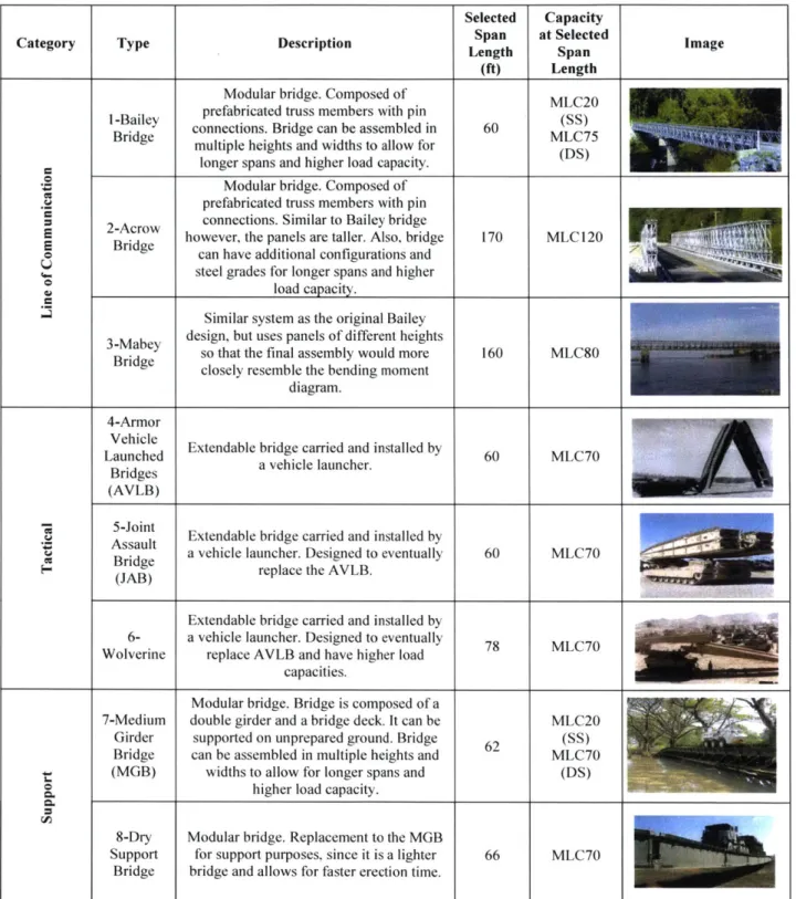
Table 1-Existing types of portable temporary bridges used for military and civilian applications.
Support and line of communication bridges are modular bridges whereas the tactical bridges are deployable as defined in the context of this study [7,20-27]... 16 Table 2- Design dead loads based on self-weight of structural and non-structural components and
design live loads per AASHTO H-15 loading configurations [19] ... 27 Table 3- 6061 -T61 Aluminum Alloy Material Properties [19]... 29 Table 4-Bridge designations based on SLE geometry and bridge deck location... 34 Table 5- Resultant deployed angle for the most optimal SLE structural performance per geometry
as defined in section 4 .2 ... 47
Table 6-Lowest cross sectional area solutions and objective function values for all geometries 49 Table 7- Resultant forces and deflections for all selected geometries ... 50
Table 8-Maximum member forces and deflections under deployment support conditions at the
critical lo catio n ... 5 2 Table 9-Design comparison with existing bridge designs. [25,46]... 57
Chapter 1 Introduction
1.1 Introduction
In the aftermath of a natural disaster, all efforts are dedicated to a common goal: repairing and bringing the affected communities back to their fully functioning condition. However, it is frequently encountered that infrastructure and roads providing access to these communities are also damaged, complicating the restoration activities. Therefore, deployable infrastructure, which can provide means of communication to the affected areas in a rapid manner, is vital for an efficient post disaster relief effort.
Preliminary reports of the infrastructure damages caused by hurricane Maria in 2017 state that approximately 18 bridges in Puerto Rico (Figure 1) were destroyed [1]. Immediate relief including the distribution of supplies and the restoration of power was delayed due to the inaccessibility to the affected locations. Similarly, other natural disasters such as landslides, earthquakes, flooding and tsunamis have caused significant damage to infrastructure. For example, In Indonesia, several bridges were destroyed and swept away by the 2004 Great Sumatra Earthquake and Indian Ocean Tsunami, leaving many small communities isolated (Figure 3) [2]. In Japan and Italy flooding caused bridges along the Hito River and the Po River respectively, to collapse (Figure 2) [3,4]. In 2010, 14 bridges collapsed in Chile as a result of the Maule earthquake. Deployable temporary bridges were installed to maintain lines of communication, while new permanent bridges were being designed under new earthquake codes [5]. These few examples, give an idea of the large degree of devastation caused by various natural disaster events, how disaster relief is a common need throughout the world, and how deployable structures can potentially be of use.
Rico 2017. leaves communities without means of ands o/-ma Im i w<> \Il/i H/ eva, i!(/io/i ()I/ U l/ nmim I /io Ai n rf1 / <I n/t,/
Earthquake and Tsunami in Indonesia 2004 /2/
Furthermore, although the need for post disaster relief may increase due to the expected increase in natural and manmade disasters [8], there is very little research on the modification, or improvement of the existing temporary bridge designs. At the moment, the majority of these were designed in the mid-20th century by the military, for military loading requirements [8-10]. These bridges, although reliable, when used for civilian applications, are subjected to smaller load conditions and therefore are conservative. Developing a bridge design which would serve the load conditions specifically required for civilian applications, can potentially provide an alternative system which is lighter and more efficient.
While the main motivation for this research is the use of deployable structures for immediate relief, there exists the potential of using the design process and concept for other applications. Examples of these are: scaffolding, temporary infrastructure for construction access, and temporary supports for new infrastructure.
A deployable structure is one that can volumetrically transform from a compact state, to a larger
deployed state when energy is applied to it [11]. Deployable structures are versatile systems with uses in diverse fields, often for their storage and transportation benefits. A familiar example of a deployable system is the umbrella (Figure 4). Umbrellas have the ability to be folded when not in use and transformed to a larger system after a force is applied.
b igure 4-xainple o/ a depoyable system. an umbrella, used regularv on a dav to day basis, in its deploVed and Ib/ded state /12/.
On a larger scale, deployable structures are used on applications ranging from temporary architectural and civil structures to space applications [13,14]. Examples of these include: deployable shelters, roofs for stadiums, temporary stages, scissor lifts, temporary bridges, solar space arrays and deployable space antennas [11,13,15,16]. The structures need to meet two different equilibrium requirements: one when they are folded, and one when they are expanded static load bearing systems during operations. Moreover, a deployable structure must also be capable of performing as a reliable kinematic system while it deploys.
Deployable bridge structures provide a solution to post disaster relief efforts. Due to their transportability and ease of installation, they can be in service at the affected locations within a relatively short timeframe [8]. As such, they have been used for temporary lines of communication and have also been used for military applications throughout the world [2,8,5]. This thesis studies deployable bridges as temporary infrastructure and presents a new alternative design for post disaster relief applications.
Deployable structures have been classified according to their morphology and kinematics, by Hanour and Levy [17] (Figure 5). For this research, we will focus on a deployable structure that belongs to the pantographs (scissor) structures subcategory. Scissor structures can be deployed by the application of a single point force, which is beneficial given the possibility of lack of resources after an event. Also, these structures have high reliability during deployment and a large volume ratio between their stowed and deployed states [14,18]. While many applications of scissor structures have been proposed, not many have been formalized and constructed due to the design complexity of the system for deployment [18].
Nevertheless, with the use of existing computational optimization methods, known deployable assembly geometries and finite element analysis, this research aims to design a light bridge structure constructed out of scissor like units (SLEs).
Morphology
Lattice DLGI
SLGI
II
IF Spine I' Pantographic (scissors)Peripheral Scissors li9
22 Radial scissors 55 0(hers 74 Angulated scissors (retractable roofs) 0 75 (1 6 Masts and arches 98 __________I a H. Bars Continuous Plates Folded Plates Linear deployment 5 Radial deploymemt Curved surface II 60 83 surface ~ 85 Reciprocal gnds (Dismountable) 10I ~it ________________________-n ______________________ i ______________________________________________ -ml * Strut-cable systems
II
II Tensioned membrane I Fabric PnCeIMal ic Low pressure H ps High pressure a E - gFigure 5-Classification o deployable structures hased on iheI morphology and kinematic characteristics [17/
11
I L. 0 4..' Ribbed 90 69 Tensegrity 97 Others1.2 Research Objective
The objective of this research is to introduce a new deployable bridge design for a short span structure aimed at immediate post disaster relief applications. With this in mind, the general design parameters to follow are: (i) geometry, (ii) weight, (iii) transportability, (iv) structural performance
and (v) energy required for deployment. Specifically, the objective is to present a structural design which satisfies the deployment constraints and is optimized for minimum weight and subjected to the stress limits determined by AASHTO and deflection limits defined herein [19].
Chapter 2 Bridges for Disaster Relief and Basis for
Design
2.1 Existing Types of Deployable Bridge Structures
For the purpose of this study a deployable structure is one that can volumetrically transform from a compact state, to a larger deployed state when energy is applied to it [11]. However, in literature the term "deployable structure" is used interchangeably to classify structures which are portable and rapid to install.
Deployable bridge structures, as defined in literature, have been designed and utilized since the beginning of the 2 0th century. Their research and implementation has mainly come from the military for combat and relief applications [8]. These bridges can be classified in three subcategories as used by the military: tactical, support and line of communication [20]. Table 1 summarizes these categories and provides a brief explanation of each. From the examples defined below, bridges on the support and line of communication categories are modular structures, whereas the tactical bridges are deployable. Although, the deployable bridges fall under the tactical classification, we would like to design one that is used as a line of communication. The extend of the bridge descriptions is only to provide a glimpse at the different available types. See references
Selected Capacity
Category Type Description Span at Selected Image
Length Span (ft) Length
Modular bridge. Composed of MLC20 I-Bailey prefabricated truss members with pin
Bridge connections. Bridge can be assembled in 60 MLC75
multiple heights and widths to allow for longer spans and higher load capacity.
Modular bridge. Composed of prefabricated truss members with pin 2-Acrow connections. Similar to Bailey bridge
9 however, the panels are taller. Also, bridge 170 MLC 120 E Bridge can have additional configurations and
steel grades for longer spans and higher
load capacity.
Similar system as the original Bailey 3-Mabey design, but uses panels of different heights
Bridge so that the final assembly would more 160 MLC80 closely resemble the bending moment
diagram. 4-Armor
Launched Extendable bridge carried and installed by 60 MLC70 Bridgesd a vehicle launcher. 6 L7
Bridges (AVLB) - 5-Joint
Assault Extendable bridge carried and installed by
Bridge a vehicle launcher. Designed to eventually 60 MLC70
c- Breplace the AVLB.
Extendable bridge carried and installed by
6- a vehicle launcher. Designed to eventually 78
MLC70
Wolverine replace AVLB and have higher load capacities.
Modular bridge. Bridge is composed of a
7-Medium double girder and a bridge deck. It can be MLC20 Girder supported on unprepared ground. Bridge 62(SS)
Bridge can be assembled in multiple heights and MLC70
(MGB) widths to allow for longer spans and (DS)
higher load capacity.
8-Dry Modular bridge. Replacement to the MGB
Support for support purposes, since it is a lighter 66 MLC70
Bridge bridge and allows for faster erection time.
Table -visting types of portable temporairv bridges used/br military and civilian applications. Support and line of
communication bridges are modular bridges whereas the tactical bridges are deployable as defined in the context ofthis stadv
2.2
Literary Review
There exists in literature the study and proposal of alternative designs for deployable bridges additionally to those outlined in Table 1. Although these have concluded with promising results providing more efficient or lighter structures, to the best of the authors knowledge literature does not at current contain examples of actual applications.
Thrall et al. [28] have used structural optimization of panel topology, and of panel height and spatial orientation to present alternative designs for modular bridges. Also, different designs such as the Pratt truss, the bowstring truss, and network tied arches have also been proposed for modular construction [9]. Lederman et al. [29] presented a vehicular launched deployable bridge with a tied arch geometry, which has an unrolling deployment sequence. Another proposed patented design is the Mobile Bridge, which is a deployable structure composed of translational rectilinear SLE units. Full scale models and testing of the Mobile Bridge have been done and published [3,30,31]. Furthermore, there exists in literature various propositions of bridge concepts for military use, using alternative materials such as composites and FRP [32-36]. Most of the works in literature although characterized as easy to transport and install, still require onsite assembly and connections. In this study we propose a design which only requires the onsite expansion of a system which is fully assembled in its folded position.
Typically scissor like element (SLE) units are divided into three main geometries: translational, polar and angulated. These types will be described in detail in section 2.4. The main geometric relationship required for an SLE structure to be stress free in the deployed and folded condition is derived by Escrig [37] and referenced as the general deployability condition (equation 1). The equation states that the sum of the lengths of the members on each side of a unit line are equal to each other [3,6,37,38]. Unit lines are imaginary lines between one SLE unit and the other, which connect the upper and lower node of the scissor unit (shown as a dashed line in Figure 6)
> b d
Figure 6- Geometric constitutive equation required jor stress f-ee SLE structures to be stressfi-ee in their deployed and fblded
condition. Reproduced from [13. 1 6,37,38]
Based on derivations from the formula above Gantes [13], Escrig [37] and Maden et al. [38] provided guidelines and compatibility equations for the geometric design of stress free deployable structures. By varying the member lengths, the location of the pivot joint, and the modes of translation, [37,38] present a review of different scissor structural mechanisms which reliably provide deployment geometries. Additionally, Chikahiro et al. [3] explored the effects of geometric changes in the SLE structure's internal stresses by varying the angle of the diagonals. The study found that when 01 ( Figure 7) is less than 30 degrees, the rate of increase of the member stresses is higher than the rate of increase at angles above 30 degrees. Our study seeks to compare the performance of the various SLE deployable system geometries in the context of a particular application, specifically, a bridge structure.
00
0
Figure 7- Single SLE unit displaying the location qf angle 01
Alegria Mira and colleagues [14] compared the structural performance of all four scissor like element (SLE) unit types: translational, polar, angulated and USC. Translational, polar and angulated units are described in section 2.4. The USC is a recently developed scissor unit and is not studied in this thesis, further details can be found in [14]. Moreover, through a sensitivity analysis, they evaluated the effects of varying geometric properties in a system such as: thickness, height-span ratio and number of scissor units. This study found that the thickness of the element
is a very important parameter of the design. They also concluded that angulated units was the least efficient, where the USC performed the best under their design parameters. Furthermore, their results using a 2D linear elastic analysis matched the results of a 3D non-linear analysis of structures, therefore validating the use of the former as an approach for the design of these structures [15]. Gantes [13] and Pellegrino [6] studied the general field of deployable structures and their applications and, presented guidelines for the design and structural analysis of these. Gantes [3], Pellegrino [6] and Alegria Mira et al. [14] presented computational models of the SLE units. Furthermore, Alegria Mira et al. [14] used zero length rotational springs to model the hinges at the exterior nodes. Whereas, Gantes [13] and Pellegrino [16] presented the node/slave technique to represent the joint between the two diagonals that make up each SLE unit. The design approach presented herein proposes a simplified process which considers deployment reliability first. Optimization methods have been used in the field to solve many problems. Gantes et al. [39] used the genetic algorithm (GA) to optimize for material and cross sectional properties of snap through deployable systems. You [40], used sequential quadratic programming to optimize for minimum weight or maximum stiffness in terms of geometry, cross sectional areas and materials [40]. Alegria Mira et al. [14] optimized arch geometries for deflections and structural performance using Rhinoceros' optimization plugin Karamba. Thrall et al. [41] used gradient-based steepest descent,
GA, simulated annealing (SA) and damped least squares (DLS) to optimize the design of
deployable structures composed of linkage elements. Also, Thrall et al. [9] used SA for minimum weight and maximum structural performance of modular bridges to find optimal length and form of panels. Additionally, on a single unit scale, Alegria Mira et al. [42] used a global shape optimization procedure for sizing, shape and structural optimization of a single unit to design the Universal Scissor Component.
The novelty of the study presented herein is the analysis and comparison of optimal SLE structures computed for various known deployable geometric configurations. At the same time, we incorporate into the shape optimization and geometric design exploration the allowable limits proposed by AASHTO, thus resulting in a concept which takes into account current code regulations. Moreover, this research presents a detailed design approach including the code variations required to properly model and analyze SLE deployable structures.
2.3 Proposed Concept Design
Following the design parameters outlined in section 1.3 of (i) geometry, (ii) weight, (iii) transportability, (iv) performance, and (v) energy required for deployment, we propose a deployable bridge design composed of SLE units. To form a structural system, the units are jointed to each other at their external top and bottom nodes to create a lattice. The bridge will be composed
of two lattices which will be joint by transversal members supporting the deck.
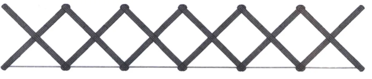
During the initial exploration phase, small models were constructed to understand the behavior of SLE-type structures and to ensure that the geometry was feasible for our bridge application. The small scale models were built at MIT, using wood coffee stirrers for the rigid members and staples for the revolute joints and hinge connections. The lack of vertical and horizontal members, and the fact that the members in each unit are free to rotate at the hinge connections, allows the system to contract and expand. This characteristic, which facilitates transportability, makes SLE systems a great potential candidate for a deployable structure. An example of a lattice for the SLE bridge model in the deployed and extended condition is shown in Figure 8.
kigure N- 2-1) SL E model or a rectilinear translational geometry made out ofwood coffee stirrers and staples. The image on the left shows the structure in its folded position. The image on the right. shows the structure in its deployed state at an arbitrary angle.
2.4 Scissor Like Element Structures
SLE units are structural units composed of two rigid members. The members are linked together by a common pivot joint, allowing independent rotations along the axis normal to their common
0O
Pivot joint
0
Figure 9- Example of a two dimensional translational S.E unit consisting of two identical rigid beams jointed by a single pivot
joint in the middle.
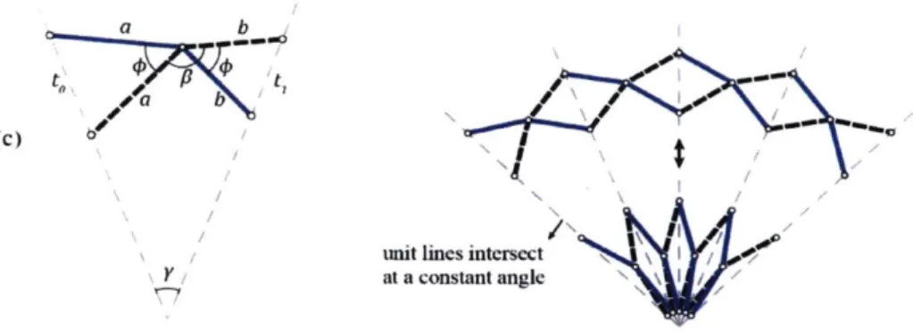
Based on the orientation of the unit lines and on the geometry, SLE's are categorized in three basic units: translational (Figure 10 a),polar (Figure 10 b), and angulated (Figure 10 c) [5,42,43]. Translational units, have two identical straight members and their pivot joint is in the middle of the member. When deployed, the unit lines are parallel to each other. Polar units, also have two identical straight members but the location of the pivot joint offset, creating a curvature during deployment. The unit lines meet at an angle y which increases during deployment. Lastly, angulated units, are characterized by angled members which allow the structure to deploy in a radial configuration. The unit lines intersect at an angle y which remains constant during deployment [5,42,43].
a
(a) to t
o a b
parallel unit lines
a
t I
(b) b dc
unit lines intersect
a b
(C)
unit lines intersect
at a constant angle
Figure 10-SLE basic unit types in the/bi1ded and deployed position: a)translational unit, b)polar unit, c) angulated unit 1381 Scissor structures can be formed by interconnecting SLE units together at their end points. When assembling these structures, geometric considerations must be carefully studied, not only to provide the desired final shape, but also to ensure a compatible and deployable system. Geometric compatibilities, which define the kinematic behavior and stresses during deployment, are dependent on the type of SLE unit selected and on the overall system geometry. When all the members of the structure fit together without deformations, i.e. without stresses, it is said that the structure is geometrically compatible. If this compatibility exists at all stages of deployment, then the structure is defined asfoldable [44].
An essential geometric requirement for a stress free system is the general deployability condition shown in equation 1. Satisfying equation 1 ensures a stress free and compatible condition in the folded and deployed state for all members. It also ensures that when jointed together, SLEs create a system where all members in the linkage reach their most compact state at the same time. Thus, reducing the linkage theoretically to a single line, though discrete joint and member sizes dictate the actual size of the system [5,13,44].
However, this condition alone does not ensure geometric compatibility during deployment [16]. Additional considerations, as defined by Gantes and Maden et al., need to be satisfied to provide a stress free deployment, and therefore a foldable structure [13,38]. These conditions can be satisfied by following derived geometric and trigonometric equations which relate member lengths, symmetry, deployment angles, total span length and unit height. These equations, and the geometric systems reviewed by Maden et al. [38] are used in the development of the deployable bridge design described herein. It should be noted that a foldable structure, although stress free in the compact and deployed state, is not stable in the deployed state. Therefore, the system requires the addition of external locking mechanisms to create a rigid load bearing structure [13,44].
Chapter 3 Design
3.1 Design Process
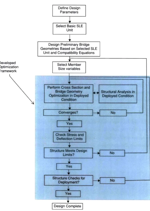
The design process for a deployable structure is complex: it is a multistep iterative approach that requires both a detailed geometric analysis for deployment, and a structural analysis for stability at all stages of deployment, including of the folded and fully expanded states. Although the structure's behavior is usually linear in its deployed configuration, it is highly nonlinear and more complex during deployment. Therefore, it is generally recommended to first design the structure in its deployed configuration, and then check it for deployment stability [13, 16]. However, the design presented in this paper, as schematically illustrated in Figure 11, uses a simplified approach where we select an already deployable system as the basis for our design. To do so in an effective manner, our approach selects geometric systems which have already been proven to work for deployment based on a user defined SLE unit type. These, together with member cross sections, are provided as design variables for the structural analysis and optimization of the bridge in its deployed condition. The bridge geometry and member sizes are optimized for a minimum weight objective function. In this step, the structure is subjected to the parameters and loadings described in section 3.2. and designed to meet equilibrium requirements, stress limits as stipulated by
AASHTO guidelines [19] and deflection limits as defined herein. Nevertheless, upon completion
of the optimization and design in the deployed condition, the final configuration is checked to confirm deployment. The optimization scheme is described in detail in chapter 4.
Design and Optimization Process
Define Design
Parameters
Select Basic SLE
Unit
Design Preliminary Bridge Geometries Based on Selected SLE
Unit and Compatibility Equations
Select Member Size variables Developed
Optimization Framework
Perform Cross Section and Bridge Geometry Optimization in Deployed Condition
H
Structural Analysis in Deployed Condition Converges? Yes Check Stress andDeflection Umits
Yes
No
Design Complete
Figure I I-Herein developed framework for the design and optimization o/ a deployable bridge structure. The /rainework is used
fbr the design n/the bridge structure in this studv'
Structure Meets Design uLmits?
Structure Checks for Deployment? I +No -+No I I I
3.2 Design Parameters
The proposed bridge design is aimed at immediate post disaster relief applications. Therefore, the design parameters selected are based on the review of immediate needs after historical events and on previous studies into mobile structures. Specific needs for short span bridges for post disaster relief have been identified by the US Army in its Future Force Plan [29,35]. Furthermore, studies within the field often use short spans ranging from 50.00 ft up to 65.00 ft. Thus, to allow for comparison to previously design structures, a span length of 60 ft is selected [29,41,31,45]. The maximum member length has been selected based on transportation constraints. The US Department of Transportation imposes that vertical clearances for highways should be between 14.00 ft and 16.00 ft [46]. Considering the structure is being transported in a lowboy trailer, with an approximate height of 2.00 ft [47], a maximum member length of 12.00 ft is chosen. For geometries which have SLE units with different member lengths, a length of 11.00 ft is chosen for the shorter member, D2. Lastly, for material selection, aluminum alloy has been selected for the
structural and non-structural components. Aluminum alloys provide high strength and a large stiffness to weight ratio. When compared to steel, aluminum alloys are approximately less than 1/4 of the weight yet as much as 1/3 of the stiffness. The lightness of the material is beneficial for the transportation and deployability of the system.
Another design variable explored is the location of the bridge deck. By varying the depth of the bridge deck we explore through (at SLE bottom) and half-through (at midpoint of SLE) bridge configurations as seen in Figure 12 and Figure 13, respectively.
Figure 13-Location of bridge deck fbr a half-through bridge on a rectilinear translational SLE configuration with diffrrent member lengths.
The factored loads described in Table 2 have been applied to the structure in the locations shown in Figure 14. The bridge is being designed for AASHTO Strength I limit state with a load combination and load factors defined in equation 2.
L = yD(DL + SDL) + yL(LL) equation 2 Where,
YD = yD-max = 1.25 for components and attachments [19]
yL = 1.75 [19]
The dead load is being applied at the center of mass of each member, whereas the superimposed dead load is evenly distributed at all loading points. The live load selected is one of the design vehicle loads as specified by AASHTO Standard Specifications for Highway Bridges [48]. Although AASHTO specifies current bridge designs to use a higher design load that the one used in this study (H-20 vs. H-15), the lighter design load was selected based on the proposed bridge application. This load criterion allows for a line of communication, the passage of relief vehicles, civilian vehicles and supplies. The design vehicle load is applied as two point loads (Figure 14) and placed at different bridge locations to find the most critical position. The design live load is distributed to each of the adjacent load bearing points as a weighted function depending on the distance to each of the points.
Load Load Description Formulation nel
Dead Load Self-weight
DL =jLbe *Ae *WA
____ ____ ____ ___ ____ ____ __ =1
Super Imposed Dead Load 1 in Thick Aluminum Alloy Deck SDL = Wd * S * WAL
Live Load H-15 Design Load (Figure LL = 30,000 lbs
14Figure 14)
Where,
A = Cross - sectional area of each member
Lbe = Length of each member
S = Length of bridge span
WA, = unit weight of aluminum = 0.1013 lb/in3 wd = width of bridge deck = 4 ft
S = Length of bridge span
Table 2- Design dead loads based on sell-weight ofstructural and non-structural components and design live.loads per AASHTO
H-15 loading configurations [19]
24,000 lbs 6,000 lbs
Figure 14-AASHTO H-15 loading configuration. Adaptedftomn [49].
The design and loading parameters described above are shown in Figure 15 for an example of a translational rectilinear through bridge geometry. Additional bridge geometries will be studied in this work. Further details describing the different configurations are provided in chapter 4.
Design Parameters & Loading
60 ft. Aluminum Alloy
DL DL
Figure l.-)C'sugn palrtlIcers and loads used/lor the development o/ the proposed bridge, for a translational rectilinear bridge configuration.
After the design of the bridge in the deployed condition, the structure is checked for deployment to ensure that the members do not exceed the allowable stresses and bending moments. For deployment analysis, the selected optimal bridge geometry is analyzed as a cantilever, assuming that the most critical condition is when the bridge is close to full deployment. That is, at an approximate 60-foot span, before reaching the end support. In this condition, the structure is subjected to its self-weight and the weight of the bridge deck (Figure 16). The top and bottom beam members of the lattice are fixed with rigid connections. Due to the higher complexity in the construction of fixed connections, we also analyzed the cantilever structures with pin-pin connections.
DL+SDL (typ)
Figure 16
-Supports and loading scheInaticfor deployment check ofthe structure for pin-pin connection cantilever option
The material properties for the aluminum alloy selected for the design are outlined in Table 3 below, per AASHTO LRFD Bridge Design Specifications [19].
Specification B209
Alloy-Temper 6061-T6, T651
Ultimate Tensile Strength (Ftu) 42 ksi
Yielding Tensile Strength (Fty) 35 ksi
Ct (unwelded) 141
Compressive Yield Strength (Fy) Fty
Modulus of Elasticity (E) 10,100 ksi
Shear Modulus of Elasticity (G) 3,800 ksi
Poisson's ratio 0.33
Shear Yield Strength (Fy) 0.6*Fty
Shear Ultimate Strength (Fu) 0.6*Ftu
Table 3- 6061-T61 4luminum Alloy Aaterial Properties [19]
Chapter 4 Geometric Design and Size Optimization
4.1 Design Approach
A nested approach is proposed for the design problem which simultaneously explores the different
geometric configurations and optimizes the member's cross sectional areas. The overall problem objective is to minimize the weight of the structure subject to deployability constraints, equilibrium, and stress and deflection limits. Through this approach, we aim to compute a solution which provides an optimal geometric and member size combination. Both the optimization formulation and geometric design are defined below.
The sizing optimization is defined as a formal optimization problem and solved using a constrained genetic algorithm with discrete variables. The design variables are the cross sectional depths and thicknesses and the sets of discrete options is defined by the user. The size optimization is performed simultaneously with the geometric design study. Since our approach has a low number of variables in the geometric design problem, it was computationally feasible to check all points in the design domain, thus ensuring a global optimal solution within the given domain.
4.2 Geometric Design
The first step for the geometric design of the structure is to define a SLE unit based on the design parameters. For this specific application, translational units were selected as the basic element of the system. Many of the studied structures in literature use translational units as their main design unit [13,44]. Comparatively, in previous research, angulated units proved to be the least efficient units for the studied structural systems [5]. Also, polar units create too large of a vertical curvature to be utilized as a bridge without additional considerations for the supports. Therefore, both, the angulated and the polar units were opted out of the design.
Once a design unit was selected, a variety of system geometries for this unit were explored. The selection of the proposed systems was done by choosing deployable SLE geometries for
translational units already presented in literature [38]. Based on their derived trigonometric and geometric equations for foldability, the structures were modified to meet our design criteria. Once selected, the translational geometries were defined within the model as a function T(x) of predetermined nodal point locations, and are represented as T(1), T(2) and T(3) which are discussed in detail below. The geometries were all evaluated by the structural analysis program and the size optimization scheme. Furthermore, all geometries were evaluated at various angles of deployment 61, ranging from 24 to 46 degrees measured from the horizontal to the main diagonal (Figure 17).
I
24
65
1:546
Figure 17-Range of the design domain fwr variable angles illustrated in a rectilinear translational geometry. All angles were evaluated for the three structure geometries proposed.
Through the design process, we computed and stored the optimized cross sections for all the different geometries in the design domain and subsequently compare them. The most optimal solution to our problem is a solution with the minimum weight across all geometries.
The three translational geometries T(1), T(2) and T(3), are illustrated in Figure 18, Figure 19 and Figure 20 respectively. T(1) defines a rectilinear translational geometry composed of identical members with pivot points at the mid-point of all elements. The pivot and external joints of each
Co C, C2 C3 C4
Al A2 As A4
B B3 B2 B3 B4
SS
Figure 18- T( 1) structure geometry explored in bridge design. Rectilinear translational system composed of identical units with pivot points at the mid-point of each member. Geometry is derived from comnpatibiity equations for translational units [381.
T(2) is a rectilinear translational geometry composed of identical SLE units which have members of two different lengths. The members of equal length run parallel to each other and the pivot locations are at the mid-point of each element. The SLE units repeat identically up to the middle of the bridge span. The reverse configuration is then constructed thus creating an arch like structure, illustrated in Figure 19._______Mropln
C4 3 C2B A( t A B 2 ID SS -_ B _-_ - -x - _ _ _
Figure 19- T(2) structure geomety explored in bridge design. Rectilinear translational system composed of SL E with different member lengths aind pivot points at mid-points of each member. Bars of the same length run parallel to each other up to the mid-span. By mirroring the geometrv along the y axis, an arch like structure is created. Geomety is derived fom compatibility'
equations /6r translational inits [38].
T(3) defines a rectilinear translational geometry composed of SLE units which have members of two different lengths. The SLE units are not repeated throughout the system. On the contrary, the lattice is constructed by
jointing
an SLE with its reverse configuration. This causes, as illustratedin Figure 20, members of the same length to be connected to each other. Though the revolute joints share the same elevation coordinate, the exterior hinges do not. This consideration is taken into account in the design by allowing the deck to be located in the middle of the structure as a half through bridge only.
C, C3 C-0 C2 C4 A, A2 A3' ~A4 t t S2t t 01 B B3 B0 S B2 B4 S
Figure 20- T(3) Structure geometry explored in bridge design defined as a rectilinear translational system composed of SLE
units with difjerent member lengths. Each unit is connected to a reverse configuration of/itself allowing bars of the same length to be connected to each other. Geometry is derived from compatibility equations for translational units 1381.
By combining the three structure geometries along with the bridge deck depth variables, a total
of 5 main configurations are studied. The configurations and their proposed designation for the purposes of this analysis are listed in Table 4.
Bridge SLE System Bridge Resultant
Designation Geometry Type I TThrough
T(1)-A T(O) Bridge---- ----X
----.. ....---Half T(l)-B T() Through Bridge Through ... T(2)-A T(2)
Bridge
Half T(2)-B T(2)Through
Bridge Half T(3)-B T(3) Through ---Bridge4.3 Shape Optimization Problem Formulation
The objective of the shape optimization problem is to minimize the total weight of the structure subject to: the geometric layouts defined in the outer level, the stability of the structure and, the deflection and stress limits. The objective function is defined in equation 3 as follows:
min Ae,e = 1-...nel Subject to nel h Lb" *Ae *WAI e=1 Kd = F for all n = 1: nnp
for all e = 1: nel
for all e = 1: nel
for all e = 1: nel
Equilibrium
Where,
A= Cross - sectional area of the section
c= Def lection limit
d = Element displacent vector
F = Element force vector
h = total weight of the structure
K = Global stiffness matrix Lbe = length of each element
nel = Number of elements
nnp = Number of nodal points
WAI = Unit weight of Aluminum
The constraints c2, c3, ... , cn are the design limits as stipulated by AASHTO [19] and will be described in detail in section 4.4 below.
4.4 Optimization Problem Constraints
The first design consideration in Eq. 4 is the equilibrium of the structure. It is calculated using a frame finite element analysis code. To meet equilibrium, the structure must satisfy equation 4. Details regarding this analysis are provided in section 4.6.
Kd = F [equation 4] [equation 3] ci 5 0; C2 5 0; C3 5 0; C4 5 0;
AASHTO LRFD Bridge Design Specifications, contains no specific guidelines for temporary
and/or deployable bridges and therefore Mmax, Fmax and Vmax are calculated based on this code under Section 7, Aluminum Structures [33]. However, since the structure is not meant to be permanent, we have in this work calculated dmax as an average between the limits found in
AASHTO and those found in literature for the design of similar bridges [19,35,45]. Stress and
deflection limits are defined for each element and thus, all elements of the system must meet the defined constraints in Eq. 4.
The constraint c1 ensures the deflection limits are satisfied. Deflection limits in literature range from Span/800, as defined by AASHTO [19] for permanent bridge structures, to Span/100 used
by Bank and colleagues in the design of military deployable bridges [45].
Considering the proposed structure is being designed for temporary applications, a more flexible deflection limit dmax is defined as S/400. Thus, constraint c1 is defined as follows:
Ci = dmax -
IdnI
0 [equation 5] Where,S
400= dmax
dn = node displacements
S = Length of bridge span
The constraint c2 restricts the maximum bending moment Mmax. The maximum moment is
calculated per AASHTO V7 section 7.11 [19].
C2 = Me - Mmax 0 [equation 6]
Where, Mmax = 0Mn
For which the reduction factors, 0 = Oft = 0.75 for flexural tensile rupture and 0 = 0.90 for
other flexural limits. Furthermore, the allowable bending moment, Mn, is calculated from the minimum value between, yielding flexural strength, rupture flexural strength and lateral torsional buckling.
I
MY Yielding Flexural ResistanceM, =min Mr Rupture Flexural Resistance
Mtb Lateral Torsional Buckling
The defined limits can be calculated per the equations found below.
My= 1.3 Fy S Mr = 1.42 * F* S Mtb = Fnb * S; Where, d Lb d Lb Cbr Bbr 2.3Dbr - if < rt Cbd t Cd 2.3 Fnt -- ~ nb T w2 E .d Lb Cbr d
(
Lb if Cbd - 2.3 5.29(
) \Cbd) Cb = 1 per section 7.10.2.2.3 [19]Dbr, Cbr, Bbr= buckling constants per table 7.5.4.3.2 [19]
d =cross-sectional depth
Lb = Lb' = unrestrained length of each element
Me= maximum bending moment at each element due to applied loads. t = cross-sectional thickness
The inequality constraint c3 restricts the maximum allowable axial force Fmax. It is calculated per reference [19], sections 7.8-7.9 as follows:
C3 = IFneI - |FmaxI ; 0 [equation 7]
The factored tensile resistance Fmax shall be taken as 0Pnt for which 0 = Oy = 0.90 for axial
tension yielding and 0, = 0.75 for axial tension rupture. The nominal resistance Pn is the least
of the nominal compressive resistance for tensile yielding and for tensile rupture which are represented and described below.
PPyin Tensile Yielding
fPt I Tensile Rupture
Py= Fty * A Pu =Fu * A
The factored resistance for compression members Fmax shall be taken as OP, where 0 = 0, = 0.90 for axial compression. The nominal resistance P is the least compressive resistance of the
following:
(mb
Member BucklingP = min Plb Local Buckling
(PM- Member and Local Buckling
Interaction Pmb = F * A For which nel Plb = FnceAe + Fcy(Ag -e=1 nel >LAe) e=1 2 Fe'A .857r2 E Pm-lb K ;2 . r) min ImPlPmb if Fe<Fc otherwise KI 85(Bc - Dc r-) : Fy .851 2E (I )2 b F if-t b Bp 1.6Dp -t k2 fB E 1.6 b t K1 if - <Cc r K1 if ->C r c B -F < p -cy 1.6DP B -F b if -< - 1.6De t -b if - > t k1Bp 1.6Dp k1B 1.6Dp A Ae Ag = Cross-sectional area b = d = Cross-sectional depth
Fne= maximum axial force at each element due to applied loads
Fe = Elastic buckling stress = (1.6b/t)2 per table 7.5.4.9-1 [19] DC, Cc, B, D,, Bp= buckling constants per table 7.5.4.3.2 [19]
-- =Effective slenderness of member
r
k1, k2 = Post buckling constant for flat elements Where,
Fc =
The inequality constraint c4 defines the maximum shear resistance Vmax. It is calculated as follows per section 7.10.3 [19]:
C4 =Ve - Vmax < 0 [equation 8]
Vmax = 0V where the reduction factor 0 = 0, = 0.90 for shear. The nominal shear
resistance is calculated as follows:
Vn = Fns * A Where: b B -F F if - < S sy f ~ 1.25Ds b B5-F b Cs F= Bs -1.25DS- if B < -t 1.25DS - t 1.25 712E b CS if -> (1.25b/t)2 t 1.25
DS, Cs, Bs= buckling constants per table 7.5.4.3.2 [19]
Ve= maximum shear force at each element due to applied loads.
4.5
Optimization Methodology
The sizing optimization problem is formulated as a constrained problem with discrete design variables. A MATLAB optimization program was written using the genetic algorithm ga function [44] which runs simultaneously with the bridge geometric exploration. The problem is constrained
by structural stability and stress and deflection limits, therefore, a beam finite element analysis
code (FEA) is nested into the GA optimizer for the analysis of the structure.
The genetic algorithm (GA) is a stochastic search method which solves constrained and unconstrained optimization problems. The algorithm is inspired on Darwin's theory of natural selection [41,50,51]. The GA starts with an initial random population, where each individual is evaluated on the objective function. Depending on the individual's performance, members of the first generation are selected as parents for a new generation. The next generation is created by a combination of the fittest members carried over from the previous generation, and of children created through mutations and crossovers of the selected parents. This combination provides a generation with a better average objective function. Crossover children are created by combining "chromosomes" from pairs of parents of the current generation, whereas children from mutations
are created by altering "genes" of individual parents [51]. Each generation is an iteration of the algorithm and continues from generation through generation until a stopping criterion is reached. Figure 21 provides a representation of the creation of children for the next generation through either elitism, crossover or mutation. GA is used in many fields including structural applications and sizing optimization. However, due to the nature of its random variable evaluation there is no guarantee the output solution is the globally optimal solution. To reduce the risk of converging to a bad local minima, the problem is evaluated multiple times and the result with the smallest area is selected as the most optimal result.
(rsoew (hid
0
so
Wurm hid
Figure 21 - Types of children created fiom generation to generation in a genetic algorithm [501
4.6 Structural Analysis
In an effort to have an efficient interface between the optimization program and the structural analysis program, the SLE structure is analyzed using a finite element method programmed in MATLAB [50]. Furthermore, the use of a MATLAB code for the structural analysis provides the ability enrich the standard FEA to match the conditions of the deployable bridge. Therefore, special considerations are taken into account for the modeling and analysis of the structure. These include the proper element selection and discretization, as well as the appropriate end node behavior and connections. Review of a standard FEA frame analysis is beyond the scope of this thesis and the reader is referred to [53] for more information.
An SLE unit is composed of two independent rigid bars which have a node at their pivot point location as illustrated in Figure 22 and Figure 23. Each bar is modeled as two separate beam elements, and the node at the pivot point rigidly joins them together (nodes 5 & 6 in Figure 22).