Publisher’s version / Version de l'éditeur:
Vous avez des questions? Nous pouvons vous aider. Pour communiquer directement avec un auteur, consultez la première page de la revue dans laquelle son article a été publié afin de trouver ses coordonnées. Si vous n’arrivez pas à les repérer, communiquez avec nous à PublicationsArchive-ArchivesPublications@nrc-cnrc.gc.ca.
Questions? Contact the NRC Publications Archive team at
PublicationsArchive-ArchivesPublications@nrc-cnrc.gc.ca. If you wish to email the authors directly, please see the first page of the publication for their contact information.
https://publications-cnrc.canada.ca/fra/droits
L’accès à ce site Web et l’utilisation de son contenu sont assujettis aux conditions présentées dans le site LISEZ CES CONDITIONS ATTENTIVEMENT AVANT D’UTILISER CE SITE WEB.
Research Paper (National Research Council of Canada. Division of Building
Research); no. DBR-RP-574, 1973
READ THESE TERMS AND CONDITIONS CAREFULLY BEFORE USING THIS WEBSITE. https://nrc-publications.canada.ca/eng/copyright
NRC Publications Archive Record / Notice des Archives des publications du CNRC :
https://nrc-publications.canada.ca/eng/view/object/?id=54909c06-785c-4424-a49f-683abec7c626
https://publications-cnrc.canada.ca/fra/voir/objet/?id=54909c06-785c-4424-a49f-683abec7c626
NRC Publications Archive
Archives des publications du CNRC
This publication could be one of several versions: author’s original, accepted manuscript or the publisher’s version. / La version de cette publication peut être l’une des suivantes : la version prépublication de l’auteur, la version acceptée du manuscrit ou la version de l’éditeur.
For the publisher’s version, please access the DOI link below./ Pour consulter la version de l’éditeur, utilisez le lien DOI ci-dessous.
https://doi.org/10.4224/40001664
Access and use of this website and the material on it are subject to the Terms and Conditions set forth at
Fire resistance of protected steel columns
Ser
TH1
N21r2
no.
574
c . 2BLDG
NATIONAL RESEARCH COUNCIL OF CANADA
CONSEIL NATIONAL DE RECHERCHES DU CANADA
FIRE RESISTANCE O F PROTECTED
STEEL COLUMNS
by
T. T.
Lie and W. W. Stanzak
Reprinted from
Engineering Journal
American Institute of Steel Construction
Vol. 10, No. 3, Third Quarter, 1973
p. 82
-
94
Research Paper
No. 574
of
theDivision of Building
ResearchLA RESISTANCE AU FEU DES POTEAUX D'ACIER PROTEGES
Les auteurs examinent, au moyen de mkthodes techniques experimentales et analytiques, la rksistance au feu des poteaux d'acier protkgks par des matieres isolantes
2
faible densite. Ils calculent les temperatures critiques de ruine et dkcrivent des mkthodes servant a calculer I'augmentation d e la tempkrature. Ils proposent des methodes simples et pratiques pour la protection des poteaux mktalliques de construction contre le feu, avec exemples a I'appui.f
f
1
!
t
iD
F I1
F
F I R E RESISTANCE O F P R O T E C T E D S T E E L COLUMNS
Lby
f.
?.- .-
T.T.
Lie:: and W.W. Stanzak4:s
i
c
E-
tI
IA b s t r a c t
b i l,
t 5The f i r e r e s i s t a n c e of s t z e l co!.urnns p r o t e c t e d with low d e n s i t y
i n s u l a t i n g m a t e r i a l s i s examined by e x p e r i m e n t a l and a n a l y t i c a l
e n g i n e e r i n g m e t h o d s . C r i t i c a l i.ernp;.,rature s f o r f a i l u r e are. d e r i v e d
and m e t h o d s f o r calcillating t e m p s c a t x r e r i s e a r e d e s c r i b e d .
Simple m e t h o d s suitable f o r p r a c r i c a i u s e i n the d e s i g n of f i r e
p r o t e c t i o n f o r s t e e l buiiding c ~ i - ~ l ~ s
?.yep r o p o s e d and t h e i r u s e
i l l u s t r a t e d by e x a m p l e s.
Key Words:
f i r e r e s i s t a n c e , p r o t e c t e d s t e e l coluraas, h e a t t r a n s f e r , c r i t i c a l
t e m p e r a t u r e , design f o r m u l a s
---
:::
R e s e a r c h O f f i c e r , ?$ire R e s e a r c h Sectio;:, Division 01 Building R e s e a r c h ,
National R e s e a r c h Council of Canada.
Fire Resistance of Protected Steel Columns
T. T. LIE AND W. W. STANZAKFULLY DEVELOPED building fires generally attain gas
temperatures in the order of 2000°F. As the mechanical properties of steel deteriorate rapidly a t teinperatures of about one half this magnitude, it is necessary to provide some rneans of keeping steel colunlns relatively cool during exposure to fire, with the possible exception of extremely massive stecl sections.' External insulation of a steel section to prevent excessive heat transfer during the expected period of firc exposure,': is the most com- mon neth hod of providing fire resistance, although inter- nal liquid-cooling has recently provecl to be a viable protcction methocl as well.
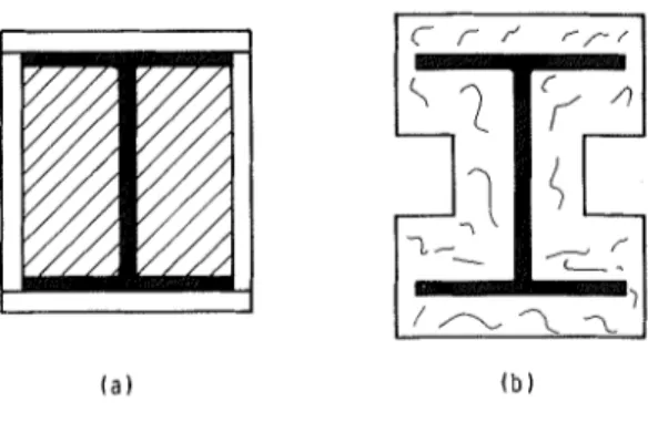
Typical forms and methods of fire protection in cur- rent usc are illustrated in Figs. l to 4. Light protection (Fig. 1) using low density materials appliecl eithrr to the profile of a section or in box forill is most popular from an economic point of view. Massive protection, par- ticularly concrete encase~ncnt, is used in special cases and forms the subject of a separate study.3 External protections, which d o not readily fall into either of thesc categories, have been labelled "complex protection" (Fig. 3) bccausc their analysis may require special meth- ods or engineering judgment. Box protected 13-columns with core filling or very thick contour protection arc examples. Liquid filling as fire protection (Fig. 4) can be accoinplished by use of design illcthods described in Refs. 3 and 4. This paper will confine itself to the fire re- sistancc of steel colun~ns protected by relatively low- density materials, examining the problcrn by both fun- damental and experiinental engineering methods.
T h e ability to maintain its loacl carrying capacity is the only pcrformance requirement of a building colunln
T . T . Lie is Research O#cer, Fire Research Section, Division of Build- ing Research, National Research Council of Canada, Ottazoa, Canada.
M '
. W . Stanzali is Steel Industries' Fellow, Division of Building Research, ~Vational Research Council of Canada, Ottazua, Canada.
*
Fire regulations and "stantlarrls" concern themselves only with pedornzance (luring afire test, not with the degree of (lamage suf- fered by a structure or its possible reusability after afire.during fire exposure. Consequently, the first applicable North American firc test standard5 required a sanlple a t least 9 f t in length to be tested under an applied load calculated to develop the theoretical working stresses of the design. I n this standard the column is required to sustain the appliecl load for a period equal to the length of time for which classification is desired. Such classifi- cations, measured in hours, form the basis of column protection required by building regulations.
Experience with the loaded column fire test indicated that failure of a protected stcel column was reasonably predictable on the basis of the temperature attained by the steel cross section. This newer alternate test of protec- tion for structural steel columns requires that a sanlple a t least 8 ft in length be tested in a vertical position without appliecl load. T h e test is applicable when the protection is not required by design to carry any part of the colunln load. T h e applied protection must be restrained against longitudinal t h ~ r m a l expansion greater than that of the stcel column. Tcmperatures are measured by at least three therinocouples located a t each of four levels (cross sections). T h e upper and lower lcvels arc 2 ft from the ends of the steel column and the two inter- nlediate levels are equally spacecl. T h e test is considered successful if the transmission of heat through the protec- tion during the periocl of fire exposure for which classi- fication is desired does not raise thc averagc (arithnleti- cal) temperature of the stecl a t any level above 1000°F, or above 1200°F at any one of the measured points.
( a ) B o x P r o t e c t i o n ( b ) C o n t o u r P r o t e c t i o n
E g . 7 . Light protectiou
82
Fig. 2. Massive protection
These methods are stated in the current version6 of the fire test standard, and standard test nlethods used in othcr countries are essentially similar.
T h e expense involved with large-scalc fire testing (in thc orcler of several thousand clollars per tcst) has en- couraged a more fundamental approach to thc evalua- tion of fire resistance. T h c prescilt paper is the most recent cffort, and is based on the findings of other re- search workers and the results of many calculations and experiments by the authors. Although the methods used to derive the information that follows were often coinplex and expensive, an cffort was inade to find those most suitable for practical use in the design of fire protection for steel building columns.
CRITICAL TEMPERATURES AND STRUCTURAL DESIGN
T h e critical tcinperature of a steel column is defined as the cross-scctional averagc temperature at which the mcmber can no longer pcrform its load-carrying func- tion; it is the cross-sectional average tempcraturc a t which the factor of safety incorporated in the structural design becomcs unity. With axially-loadccl inembers the tcinpcrature at which thc column buckles" is usually re- qardccl as the critical tenlpcrature in firc resistailcc stuclics and depends on scveral factors. T h e inost signifi- cant are: loacl intensity (stress) ; incchanical propcrties of thc stecl; shape, unit mass and length: end concli-
*
D u r i n g j r e tests it has been customary to permit a lateral deflection of 6 in. or more in the United States and 3 in. i n Erlglanrl and most European countries. f i r the purposes of this work, however, failure zvill be taken as the point at zvhici~ lateral deformation due to axial load begins, i.e., the point at w11icl~ the column buckles. Buckling mean3 the point at which any structure or part of a struc- ture passes from one deflection pattern to another without a change it1 load, i.e., the point at zvhich itjirst becomes unstable. I n a f i r e test this would correspond approximately to tire point of maximum expansion. Point of n ~ a x i m u m expansion means the time at which the colurnn i s at its maximum length during the jire test. 7'11~ column temperature at this time i s usually less than the ma.n'rnum temperatztre at the time of collapse. f i r tests of short duration (up to 2 h r ) , the points of maximum expansion and ultimate ' yailure" are separated by only a f e w minutes, but for longerjire test periods tirere ?nay be a considerable time lapse betzvcctr lilt two.l a ) ( b )
Fig. 3. Complexprotection
tions; contribution of the protection to the strength of the structural unit.
I n the present study it was assumed that the protec- tion does not contribute to column strength ancl that the column is axially loacled to the allowable stress per- mitted by the American Institute of Steel C o n ~ t r u c t i o n . ~ Accordingly, the following expressions were uscd in the calculations :
where
T h e allowable strcsses calculatccl with the above cquatioils arc similar to thosc specificcl in several other c o u n t r i e ~ . ~ " o ~ "
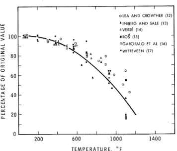
T h e incchanical properties that inost significantly affcct the critical tclllpcrature of a stecl column are illoclulus of elasticity ancl yield strength of thc stcel. Both decreasc as temperature increases. Data concerning the clependencc of these propcrties on tenlperaturc havc been reported by several autl~~rs.~"-'~hileasurccl values of the modulus of elasticity ancl the yield strength of various structural carbon stecls (ASTM A36, St-37,
Fig. I. Liqrrid-jilliny a s j i l e protection
I
o L E A A N D CROWTHER (12)1
w ' I N B E R G A N D SALE (13) 3 2 A V E R S ( (14) IRO? (15) - 2 O G A R O F A L O ET A L (16) - a Z-
80 - - C3-
- E - 0 u. 6 0 - - 0 - w - 0 C3 ," 4 0 - 0 - Z w - - 0 Dz 20 - - - - T E M P E R A T U R E , " FFig. 5. Morlulus of elasticity of carbon steels as a function of temperature
CSA G40.12) as a function of teinperature are plotted in Figs. 5 and 6. T h e wide spread in the data can be attributed to many factors, the most important probably being the variability of steel quality and thc influence of strain rate and creep properties on the test results.
Curves have already been drawn20 to suit an analyti- cal expression as well as the data reported in the litera- ture. These will be used to evaluate the critical ternDera- tures of steel columns and their dependence on column size, shape, and length. T h e authors point out that the yield strength curve represents the average decrease with temperature, but the modulus of elasticity curve, be- cause it represents the inore important variable, is somewhat conservative. T h e appropriate analytical ex- pressions for yield strength and rnodulus of elasticity are: F, = ~ , , ( 1 - 0.780 - 1.890~) (4)
and
E = E,(I - 2.040~)
respectively. In these equations
I I I I I I I I INGBERG A N D SALE (13) 1 R O ~ (1s) OGAROFALO ET AL (16) .SIMMONS A N D CROSS (18) - WITTEVECN (171 ' H A R M T H Y A N D STANZAK (19) - - - - - - - - T E M P E R A T U R E , O F
Fig. 6. Yield strength of carbon steels as a function of temperature
2) T h e influence of creep is negligible a t tempera- tures below approximately 95O0F1\nd will not be separately taken into account. I t should be realized, however, that the presence of creep deformation is al- ready inherent in the expressions for mechanical proper- ties used in the calculations.
3) T h e stress-strain curve at elevated temperatures can be obtained from an expression similar to that pro- posed by Galambosn for normal service temperatures:
T h e following method was used to calculate buckling stresses and critical temperatures for steel columns with various slenderness ratios:
For stresses below the yield strength of the steel the buckling stress F,, is given by
T h e following assumptions were made in the calcu- lations :
1) T h e effect of residual stresses can be ignored for rolled profiles. As these are clue to stresses caused by faster cooling of the outer flanges than the flange-web junctions, it follows that on rapid heating the process is reversed. With longer fire resistance times, say 2 hr or morc, sufficient time for stress relief clue to metallurgical changes is available. With colcl-rolled ancl welclecl sec- tions the effect of residual stresses ma); be significant where fire cxposure is brief.
(5) where E, is the tangent modulus obtained by differenti- ating Eq. (6), so that
For low slenderness ratios the calculated values of
F,, will exceed the yield strength of the steel. I n this case buckling stress is considered to be the yield strength of the steel as determined by Eq. (4), at the temperature under consideration.
Using Eqs. (4) to (8), and assuming values of F,, and
E, of 36 ancl 2900 ksi, rcspectively, colu~nn curves have been calculatecl for various steel tcmpcratures. These curves are plotted in Fig. 7, along with the AISC design curves given by Eqs. (1) to (3). T h e curves show that the
This temperature course is practically the same as that of ASTMQnd I S 0 3 2 for the first 2 hr. After that, it follows approximately the I S 0 course, beconling slightly higher than that of ASTM. I t was necessary to use such an expression of e-powers as a boundary condition in order to make the heat transfer equations integrable. 'The maximum difference in temperature, as compared with ASTM, is in the order of 6 percent.
T o illustrate the effect of slight differences in the ex- posing atmosphere, calculations were repeated using an expression that accurately approximates the ASTM curve :33
where t
5
120. Where t2
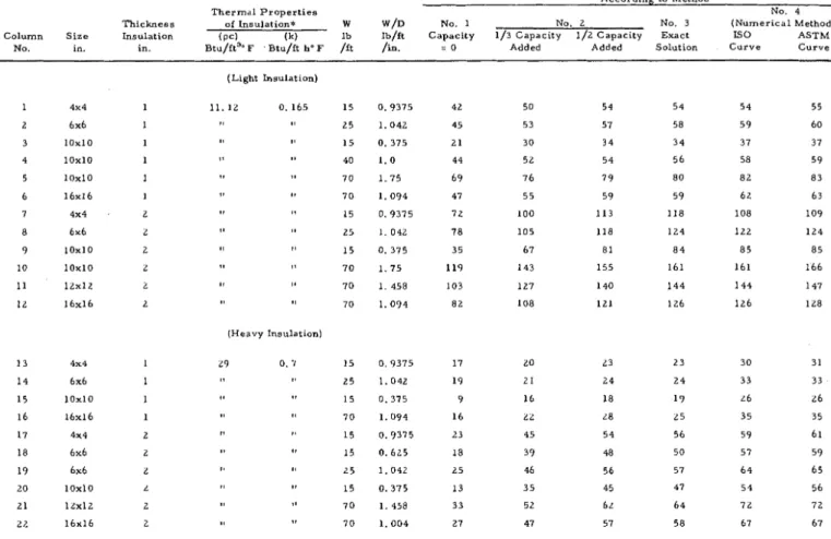
120,T h e results of these calculations are given in the last colunin of Tablc 1 and show that the differences arising out of the use of the two curves are very small indeed.
Table 1 also shows that Method 3 gives practically the same results as ~ e t h o d 4, provided the assumption in Method 3 are closely satisfied, i.e.,
(a) T h e insulation is thin in comparison with the heated perimeter, so that heat transfer is approxi- nlately one-dimensional; generally, this conditioil is reasonably achieved when 1/1)
5
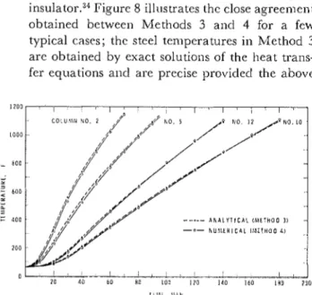
0.05;(b) T h e surface temperature of the insulation is ap- proximately equal to the fire temperature, as is tlle case with a material that is light and a good insulator." JTigurc 8 illustrates the close agreenlent obtained between Methods 3 ancl 4 for a few typical cases; the steel temperatures in Method 3 arc obtained by exact solutions of the heat trans- fer equations ancl are precise providecl the above
20 a i l 60 80 IOII I Z O 1 4 0 1 6 0 I R O a o n
l l h l i , \ l l h ,
1 .8. Tcnrperaturc rise of proterted .steel s o l ~ ~ t n n s culculated by Alctlrods 3 ar~d -./for a f e w tjyical cnsrrs (colutnn and rnatcrial
cllaractcristics arc given i n T a b l e 7 )
assumptions are met; thus, the good agreement of the results obtained by Methods 3 and 4 also proves the accuracy of the numerical method.* I n summary, the calculated results of Table 1 show the following :
1. Neglect of the heat capacity of the protective ma- terial (Method 1) gives low values of fire resistance when compared with experimental d a t a 3 h n d values calcu- lated by other methods. An estimate3"ndicates that re- sults obtained by Method 1 have practical value when the ratio
heat capacity of insulation
5
0.5 heat capacity of steel2. Adding one-third of the insulation's heat capacity to that of the steel gives better values than Method 1, but they are still low compared with the values produced by other methods and experimental data.
3. Adding one half of the insulations's heat capacity or using Method 3 (analytical) provides very good agree- ment with values obtained by Method 4 (numerical) for light insulating materials. For more clense materials, the results obtained by adding one half of the insula- tion's capacity or by Method 3 are somewhat lower than those of Method 4.
I n this case, the assumption that the surface temper- ature of the insulation is equal to the fire temperature is probably not sufficiently satisfied. I t can be s h o w d 4 that with a heavy material, i.e., the procluct kpci is large, the temperature of the surface will be appreciably lower than the fire temperature.
4. Values obtainecl using Method 4 arc the most realistic, provided the thermal properties of the protec- tive material are accurately known.
I t should be pointed out that where ~nodels 1 to 3 are used for the solution of fire resistance problenls a value can usually be obtained with the aicl of a slide rule or desk calculator using materials properties reasonably representative of those a t elevated teinperatures and often found in the literature. Application of Metliod 4 requires a high-speed digital co~nputcr and materials properties obtainable from only a limited number of laboratories, including the authors'. Method 4 is, how- ever, the one no st suitable for calculations involving protective materials containing components that undergo significant chemical reactions a t elevated temperatures, for example, cement paste and gypsum. T h e change in thermal properties of sucli materials, particularly in- crease in specific heat. will result in an increased fire -
resistance. Unfortunately, the variation of specific heat with te~npcraturc for these materials follows a n irregular
" 111 these calc~~latior~s, irypotilctical colum~ns ruiti~ box protection
having tile ci~aractcristics stated in Table 7 zucre used.
86
Table 1. Comparison of Fire Resistances Calculated by Various Methods
Thermal P r o p e r t i e s
F i r e R e s i s t a n c e ( T i m e in minutes to r e a c h 1 0 0 0 ° F steei-temperature) According to Method
No. 4
Thickness of Insulation* W W/D No. 1 No. 2 No. 3 ( N u m e r i c a l Method)
Column S i z e Insulation ( P C ) (k) lb lb/ft Capacity 1/3 Capacity 1/2 Capacity Exact IS0 ASTM
No. in. in. ~ t u / f t ~ " F . Btu/ft h " F /ft /in. = 0 Added Added Solution Curve Curve
(Light Lnsulation)
(Heavy Insulation)
+ In the calculations, a value of 0. 11 Btu/lbeF h a s been used for the s p e c i f i c heat of s t e e l .
pattern and representative values at elevated tempera- tures are often difficult to provide, rendering models 1 to 3 unsuitable for such protective materials.
For lighter materials whose heat capacity is rela- tively small, on the other hand, the influence on fire resistance of changes in heat capacity with temperature is also relatively small. By examining the results obtained by means of Methods 1 to 4, it was possible to derive simple formulas for the fire resistance of steel columns thus protected. These are accurate enough for most practical purposes, as will be shown.
DESIGN FORMULAS
T h e derivation of design formulas was based on an ex- amination of the paranieters governing the rise of steel temperature during fire exposure. Empirical formulas based on the most significant parameters were derived as will now be described.
One of the assunlptions common to all methods used in the analysis described in the previous section is that
heat transmitted through the insulation to the steel core is equal to the increase in the heat content of the steel (the heat capacity of air spaces enclosed by the insulation is always so small that it is neglected). Thus, where one- dimensional heat transfer is assurnecl (models 1 to 3), the temperature rise of the steel is given by:
T , b T .
c,W -- = Ak --I
b t bx
where
c , = specific heat of steel
W = mass of steel per unit length
A = area of protection a t the interface between pro- tection and steel through which heat is trans- ferred to the steel, per unit length
k = thermal conductivity of insulation
T , = steel temperature
T i
= insulation temperaturet = time
x = coordinate perpendicular to insulation surface.
If thermal resistance between the insulation surface and fire is neglected and a linear temperature gradient through the insulation assumed, it becomes:
where
I', = fire temperature
I = thickness of insulation
Substitution in Eq. (12) the11 yields:
which shows that the steel temperature is a function of the parameter W I I A R if the specific heat of steel is taken as a constant. Because the heated area A is proportional to the heated perimeter D, the steel temperature is also a function of WQDk.
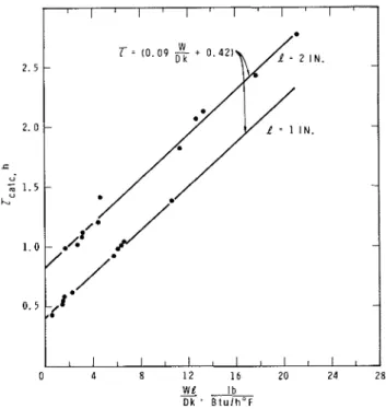
A plot of the fire resistances obtained by means of Method 4 and the ASTM fire curve against the parame- ter W / D k (Fig. 9) shows that this parameter alone can- not sufficiently describe the fire resistailce of a protected steel column. This is not unexpected, because the param- eter does not include the influence of the heat capacity of the insulation on the steel temperature. Adding an- other parameter, however, that is a function of I only, and can thus take into account to a certain degree the insulation's heat capacity, makes it possible to express the computed fire resistance by a single formula:
where C is a constant. As indicated, the term CI takes into account the heat capacity of the insulation and a value of 0.42 for C gives a good fit with the computed fire resistance (Fig. 9).
All parameters in the formula can be determined readily, except for thermal concluctivity of the insula- tion, k, which almost always varies with temperature. If a constant value of k is used, therefore, it should be chosen so as to characterize, approximately, the actual thermal conductivity a t elevated temperatures. Such approximate values are given in Refs. 34 and 37.
Normally, thermal conductivity increases with den- sity. As density is a quantity that can be readily deter- mined, an attempt was made to find a relation between density and thermal concluctivity for use in Eq. (15). Figure 10 is a plot of k vs. p and indicates that the two can be approximately related by the expression:
I t shoulcl be noted that gypsum boards, whose ther- mal properties vary irregularly with temperature because of clehydratioi~,~~ are not included in the graphs. Neither
Fig. 9. CalculatedJire resistance as a function of I4'llDk for tzoo protection thickncsscs
is Eq. (16) applicable to porous mineral wool products with a density of less than about 20 lbs,/ft3 because their thermal conductivity increases very rapidly with tem- perature owing to radiation from fibre to fibre.34 T h e reference states, however, that a value of approximately
can be used in Eq. (15) for the conductivity of mineral
D E N S I T Y , l b l f t 3
Fig. 70. Apf~roximate thermal conductivity ( k ) at elevated temf~eraturcs of various materials as a fir~zction of their h n s i t y ( p )
Fig. 7 7. Comparison belween calculated and experimentalfire resistances (calculated from Eq. ( 7 8 ) for light and chemical[v
stable prolectionr) 6 4 .c U
-
m U L 3 - 2wool in the density range 7 to 20 lbs/ft3. This illustrates that caution should be applied in the correct use of these formulas.
Generally, light, fibrous, porous materials such as mineral wool products will provide lower fire resistances than those calculated. Others that undergo chemical changes (gYpsu~n, cement paste, some concrete or plaster aggregates) will provide higher fire resistances. Chemi- cally stable materials (vermiculite, perlite, dense mineral wool, asbestos, clay) are expected to yield fire resistances very close to those calculated by the design formula. O n substitution of Eq. (16) into Eq. ( l j ) , this becomes:
7 SPRAYED FIBRE [ULI (37)]
0 VERMICULITE @LC (388
-
.
SPFAYED ASBESTOS [TNO (394o VERMICULITE
ENO
(39jl m VERMICULITE EFRO (404 CLAY BRICK ~ U T H O R S ( N R C C ~ - A SPFAYED ASBESTOS ~ U T H O R ~ (304 VERMICULITE ~ U T H O R S (NRCC)] - 0 v /-
/"
" '2 '3/':
All parameters in this expression can be readily deter- mined.
Using a value of C = 0.42 (which gave the best fit with fire resistances computed by Method 4), the ac- curacy of Eq. (17) was examined by comparing calcu- lated fire resistances with experimental data from labora- tories in Britain (JFRO), Canada (NRCC and ULC), Holland (TNO), Japan (BRI) and the United States (ULI). T h e materials in the tests wcre for the most part common, protective materials such as vermiculite, per- lite and sprayed fibres with various binders. and mineral wool. One test involvetl a clay brick. Both box and con- tour type protections were reprcsentecl. T h e comparison
I I I I
0 1 2 3 4 5
I I I I I
CEMENTITIOUS MIXTURE [ULI (374
a ASBESTOS CEMENT E N 0 (390
- -
PERLITE PLASTER [BRI (280
- -
/
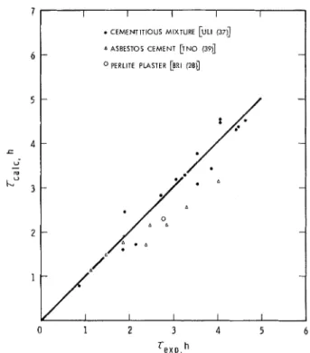
- - - /:* - .& - I I I IFig. 7 2 . Comparison between calculated and experimcntaljire resistances (calculated from Eq. ( 7 9 ) for lighl protections containing
cementitious components)
shows that calculated values of fire resistance are in fair agreement with experimental results, although generally slightly lower for chemically stable materials. As a result, the following expression was chosen as yielding the most representative answers (Fig. 11) :
for relatively lightweight protective materials (P
5
50 lbs/ ft3).For materials that contain cement paste or gypsum,
Eq. (1 8) provides conservative answers. Using C = 1.2 gives good results (Fig. 12) and for these materials the expression
should be used (P
5
50 lbs/ft3).Design fornlulas (18) and (19) were developed by a semiempirical approach and offer a far sinlpler solution to column fire resistance problen~s than has previously been available. Users should appreciate, however, that because of their generality certain pitfalls can be en- countered if the): arc applicd to a problem incliscrilni- nately, as has already been illustratccl for lnincral wool proclucts. I t is evident from the section "Tenlperaturc Rise of Protected Steel Columns" that the accuracy of calculated results can be improved for any material by
89
returning to Eq. (15) whenever sufficient test data are available.
Further examination of low-density mineral wool protections serves as an example. I t has already been stated that Eq. (16) and hence Eq. (17) are not valid for these protections. If the actual thermal conductivity of k = 0.15 Btu/ft h OF is used in Eq. (15), as has been recomniended, reasonable agreement with experimen- tal data may be obtained for the density range 7 to 20 lbs/ft3. With even lighter products, such as are normally used for sound absorption, a value of k = 0.25 Btu/ft h OF or higher was found to be appropriate.
DISCUSSION
The present study was designed to provide methods for: 1. Assessing the effect of construction (geometry) dependent parameters on the fire resistance of pro- tected steel columns,
2. Exteilsion of fire test data on protective materials to enable wider and more realistic application of known information in building construction, 3. Facilitating development of new products by re-
ducing the amount of fire test data required to gain acceptance.
Each of these items will be discussed in turn and, where possible, illustrated by examples.
1. Construction Dependent Parameters-These are the "size and shape" factor WID, the protection thick- ness I, type of protection (box or contour), and whether or not a continuous air gap is present between the pro- tective cover and steel. Quality of workmanship is naturally of vital importance, but variations therein are usually not amenable to quantitative treatment. Quality of workmanship in commercial construction generally falls considerably short of that in specimens submitted for fire test.
In the examples that follow, a W10 X49 section is used as a basis of comparison because it is the shape most com~nonly fire tested in North America. A sprayed fibre having a density of 15 lbs/ft3 serves as a typical pro- tective material
(a) Size and sllape factor WID: If a box type protection for a W10X49 with I = 0.75 is assumed, Eq. (18) yields a fire endurance time of 96 min and a fire resistance classification of 19; hr. The same protection on an 8 x 8 x
M
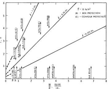
HSS (tubing, 25.4 lbs/ft) provides a fire resistance of only 70 min, making the difference between a 1% hr and a 1 hr rating. A similar rating would be obtained for a W6X15.5 section, one of the lightest rolled sections used for building colunins.Figure 13 shows how fire resistance varies with WID for a particular sprayed fibre applied to a thickness of $i-in.; typical steel sections are noted on the graph. The
W
-
D ' i n .
Fig. 7 3 . Effect of "size and shape" factor kV/D on fire resistance
fire resistance of the thickness chosen varies almost di- rectly with WID, and although the smallest columns obtain a fire rating of 1 hi-, a rating of 2 or 3 hr can be ob- tained with the same protective thickness for many sections coininonly used in high-rise steel frame con- struction.
(b) Thickness of protection I: Doubling the protection on a W10 X49 section of the previous example to 1.5 in. yields a fire resistance of 192 min or 3.2 hr. Thus, where a small margin of safety is available in a fire test provid- ing a given rating, any increase or decrease in desired rating can be provided by a proportionate increase or decrease in thickness of protection.* (This is true only if the protective material is not subject to large cracks and remains in place.)
(c) Type of protection (box or contour): The type of pro- tection has a considerable influence on the fire resistance of flanged profiles. Continuing with a W10X49 section protected with %-in. sprayed fibre, the fire resistance was 96 min with box protection but only 72 inin with contour protection, resulting in fire resistance classifica- tion of 1% and 1 hr, respectively. Figure 13 shows ex- amples of other common sections.
I n the past it has been common to relate colun~n fire resistance only to size by stating that classifications de- rived by test apply to a minimum size, for example, W10X49. This practice can be misleading in that a W12 X65 column with contour protection will have prac- tically the same fire resistance as a W10X49 column
*
McGuire et a12' have proposed that 11/1? = (i-,/~?)'.~"or iden- tical columns with different protective thicknesses. Consequently, the authors of this study caution that a margin of safety of at least71/5 should be present i n a test result for each doubling o f f i r e
resistance to be calculated by E q . ( 7 8 ) . Conversely, it is always saje to make calculations resulting i n a lesserjire resistance than one that i s known by test.
90
similarly protected. If a test were performed on the W12 column, the rating might well be rejected for use with a W10 column because the latter is "smaller."
(d)
Air
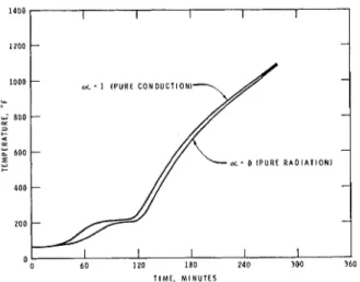
gaps: To illustrate the influence of a continu- ous air gap on fire resistance, the W10 X49 example is continued. With no air gap between the box protection and flanges, the fire resistance time was 96 min; with a I-in. air gap it is 84 min; with a 2-in. gap, 75 rilin; with a 3-in. gap, 68 niin, etc. Thus the presence of an air gap can suficiently lower fire resistance to change the fire resistance classification, in this case from 196 hr to 1 hr. In general, the presence of a continuous air gap in a construction increases its fire resistance, as is the case with suspended fire-resistive ceilings versus those di- rectly applied. With protected columns, this is only true where the air gap occurs between layers of protec- tive material, not between the protective material and the colun~n. The latter point has been proved by Lie and Harmathy31 who found that assuining heat transfer to steel by radiation or conduction produced little differ- ence in the calculated temperature rise (Fig. 14). This fact also dispels the common belief that the increase in fire endurance achieved with flanged profiles by the change from contour protection to box protection is due to the beneficial influence of the air space thus created. I t is due to the decrease of the heated perimeter D. 2. Extension of Fire Test Data-Some possible exten- sions of fire test data have already been illustrated in the examples. These can be extremely important in facili- tating the introduction of new products or methods, and in overcoming everyday problems encountered in building practice.Protection for columns smaller than the standard Wl 0 X49, for example a W6 X 15.5, has been questioned. I t is now possible to calculate the protection required on the basis of a known standard fire test result for a W10 X 49 section.
A plot such as that illustrated in Fig. 13 can also be drawn for most comnlon protective materials, using infornlation available from existing fire test data. This greatly facilitates the design of fire protection for new steel products (tubular columns are a fairly recent ex- ample) or custom-made sections. Similar design methods can be applied to protection of steel joists and beams if the heat sink effect of the floor slab is ignored.
As a final example, if an air gap is required to ac- commodate a certain non-combustible building service such as a water pipe, but test data is available only for contact protection, the increase in fire protection re- quired by creation of the air gap can be calculated. The result will usually be quite conservative owing to the extra core heat capacity provided by the building ser- vice in question.
3. New Products-Several full-scale fire tests costing many thousands of dollars are usually carried out in de- veloping and gaining acceptance for a new column fire protection material. I t should be clear that only one non-loaded fire test need be conducted, and that it should be designed so as to yield the maximum fire resistance classification that may be desired (usually 3 or 4 hr). This is necessary to ensure that the material is capable of remaining in place and relatively intact during the maximum fire exposure contemplated for the product. All other fire resistance requirements can be conservaiively calculated by means of the design formulae.
To summarize, the design formulas are very useful and their reliability increases with availability of the following information :
(a) density of the protective material
(b) knowledge of the cheillical reactions that take place while the material is heated
(c) average thernial conductivity characteristic of the behaviour at elevated temperatures for use in Eq. (15), obtained by laboratory tests or calcu- lated from fire test results
(d) a value of C, calculated from fire test data on a given material for use in Eqs. (15) or (17), that is more appropriate than the general values for C used in Eqs. (1 8) and (1 9)
(e) the amount of available fire test data, including a fire test for the maximunl fire exposure con- templated
CONCLUSION
Means of solving fire resistance problems for protected steel columns have been presented. All rely on careful engineering judgement in the choice of solution and assessment of the confidence level of that solution. With known and widely used materials, for which considerable fire test data are available, it is suggested that Eqs. (18) and (19) be incorporatecl in building regulations in the form
where
C = 0.5 for protections mainly consisting of chemi- cally stable materials such as vernliculite, perlite, sprayed asbestos with various binders, and dense
( p
2
20 Ibs/ftY) mineral woolC = 1.2 for protections containing cement paste or
gypsum, such as asbestos-cement board, plasters, and cementitious illixtures
1400
b
Greek Letters
Fig. 74. EJect of heat trarzsfer mechanism from protection to steel on the steel temperature rise
1200
Equation (17) is valid for relatively light protective materials ( p
5
50 lbs/ft3). W h e n used for heavier ma- terials, it is expected to give conservative estimates of fire resistance.NOMENCLATURE
a T h e r m a l diffusivity, ft2/h
A Area of protection a t the interface between protec- tion and steel through which heat is transferred to steel, per unit length ft2/ft
c Specific heat, B t u l l b O F
C Constant, taking into account the heat capacity of insulation
D
Perimeter of protection a t the interface between protectioil and steel through which heat is trans- ferred to steel, in.E Modulus of elasticity, ksi
F Stress, ksi
k 'Thermal conductivity of insulation, Btu/h f i "1;
K Effective length factor 1 Thickness of insulation, in.
L Height of column, ft
r Radius of gyration, ft t Time, h r
T Temperature, O F
W Atlass of steel section per ft, Ib/ft
x Coorclinatc perpendicular to insulation surface
-
-
Subscripts a Allowable CT Criticalf
O f fire i Of insulation o A t room temperature s Of steel t T a n g e n t y Yielda Fraction of insulatioil capacity added to that of steel
1000 - - cL
-
I ( P U R E C O N D U C T l O N l % 800 - - z 3 + 4 z ;; 600 - - d .d a. o [ P U R E R I \ D I A T I O N I + 400 - - - 0 I I I I I REFERENCES1. Stanzak, W . W. and T . T . Lie Fire Resistance of Unpro- tected Steel Col~~mnsJournal of the Structural Division, ASCE,
Vol. 99, No. ST5, May 7973.
2. Lie, T . T . and T . Z. Harmathy Fire Resistance of Concrete Protected Steel Columns To be publis/zed.
3. Seigel, L. G. Water-Filled Tubular Steel Columns-Fire Protection Without Coating Civil Engineering, Vol. 37, No. 9, Sept. 7967, pp. 65-67.
4. Port, L. PV., J. J . Keough, and R. W . PVollett Water-Filled Steel Columns for Fire Protection Institution of Engineers,
Vol. CE77, No. 2, Australia, Oct. 7969.
5. Standard Specifications for Fire Tests of Materials and Constructions American Society for Testing and Materials, ASTM C79-26T, 7926.
6. Standard Methods of Fire Tests of Building Construction and Materials ASTM Designation E779-77, 7977 Book of ASTM Standards, Part 74, pp. 437-448.
7. Specification for the Design, Fabrication and Erection of Structural Steel for Buildings American Institute of Steel Construction, 7969.
8. Steel Structures for Buildings CSA Star~dard S76-7969, Canadian Standards Association, 1969.
9. Canadian Structural Design Manual Suppbment No. 4 lo the National Building Code of Canada, hrational Research Council o f Canada, 7970, p. 377. (IVRCC 77530)
10. Godfrey, G. B. The Allowable Stresses in Axially-Loaded Steel Struts The Structural Engineer, Institution of Structural Engineers, Vol. 40, No. 3, 7962, p . 97.
11. Johnston, B. G. Guide to Design Criteria for Metal Com- pression Members Column Research Council, Second Ed., John
Wiley & Sons, Inc., Nezer York, 7966, p. 36.
12. Lea, F. C. and 0 . H. Crowther The Change of the Modulus of Elasticity and of Other Properties of Metals with Tem- perature Engineering, Vol. 98, 1974, p. 4S7.
13. Ingberg, S. H. and P. D. Sale Compressive Strength and Deformation of Structural Steel and Cast-Iron Shapes at Temperatures up to 950°C (1742'F) Proceedings of the American Society for Testing and Materials, Val. 26, 11, 7926,
p. 33.
14. Verse, G. The Elastic Properties of Steel at High Tempera- tures Transactions, American Society of Mechanical Engineers, Vol. 57, 7935, p. 7 .
15. Ros, M . Feuersicherheit und Feuerschutz der Stahlkon- struktionen Gutachterz erstattet an die Technische Kommission des Vcrbandes Schweizerisclzcr Briickenbau-und Stahll~ochbau-
Unternehmungen, Zurich, 1947.
E Relative strain
p Density of insulation, lb/ft3 T Fire resistance, h
ACKNOWLEDGMENT
T h e authors wish to thank Messrs. E. 0 . Porteous a n d
J. E. Berndt for their help in the experimental work a n d the evaluation of results.
This paper is a contribution from the Division of Building Research, National Research Council of
92
E N G I N E E R I N G J O U R N A L / A M E R I C A N INSTITUTE O F STEEL CONSTRUCTION
6 0 1 2 0 180 240 300 360 Canada, a n d is published with the approval of the
16. Garofalo, E., P . R . Malenock, and G . V . Smith The Influence of Temperature on the Elastic Constants of Some Commer- cial Steels, Determination of Elastic Constants A S T M S T P 729, American Society for Testing and Materials, 7 9 5 2 , p. 7 0 .
17. Witteueen, J . Brandveiligheid Staalconstructies, Centrum Bouwen in Staal Rotterdam, 7966.
18. Simmons, T4'. F . and C . C . Howard Elevated-Temperature Properties of Carbon Steels A S T M Special Technical Pub- lication No. 780, American Society for Testing and Materials, Philadelphia, 7955.
19. Harmathy, T . Z. and W. W . Stanzak Elevated-Temperature Tensile and Creep Properties of Some Structural and Pre- stressing Steels American Society for Testing and Materials, Special Technical Publication 4 6 4 , 7970, p. 786.
20. Lie, T . T . and D . E. Allen Calculation of Fire Resistance of Reinforced Concrete Columns National Research Council of Canada, Division of Buidling Research, Tech. Paper 378, August 7 9 7 2 ( N R C C 72797).
21. Galambos, T . V . Structural Members and Frames Prentice- Hall, Inc., Englewood Cligs, N . J., 7968.
22. Mitchell, N . D . Fire Tests of Columns Protected with Gypsum Research Paper R P 5 6 3 , Bureau of Standards, Journal of Research, Val. 7 0 , June 7933.
23. Ingberg, S . H . , H . K. Grigin, W . C . Robinson, and R . E. Wilson Fires Tests of Building Columns Technologic Papers of the Bureau of Standards, No. 784, U . S . Department of Commerce, National Bureau of Standards, Washington, 7927. .
24. Ashton, L . A . and N . Dauey Fire Tests of Steel Columns from "Investigation of Building Fires, Part V, Fire Tests on Structural Elements" National Building Studies, Research Paper No. 7 2 , H . M . Stationery O f i e , London, 7953.
25. Methods of Fire Tests of Walls, Partitions, Floors, Roofs, Ceilings,. Columns, Beams and Girders C S A Standard B54.3-7964, Canadian Standards Association, Ottawa, 7964.
26. Geilinger, W . and S . Bryl Feuersicherheit der Stahlkon- strukstionen IV Teil Feuerschutz uon Stahlstutzen, Verlag Schweizer Stahlbauuerband, Zurich, 7962.
27. McGuire, J. H., W . T.V. Stanzak, and M . L a w The Scaling of Fire Resistance Problems I n preparation.
28. Fujii, S . The Theoretical Calculation of Temperature-rise of Thermally Protected Steel Column Exposed to the Fire Building Research Institute Occasional Report No. 7 0 , Tokyo,
7963.
29. Pettersson, 0. Utvecklingstendenser rijrande brandteknisk dimensionering av Stalkonstruktioner Vag-och uattenbyg- garen, No. 6-7, Stockholm, 7964, pp. 265-268.
30. Lie, T . T . Temperature of Protected Steel in Fire. Paper 8 of "Behauiour of Structural Steel i n Fire," Ministry of Tech- nology and Fire O@cesl Committee, Joint Fire Research Organi- zation Symposium No. 2 , H . M . Stationery O@ce, London, 7968.
31. Lie, T . T. and T. Z. Harmathy A Numerical Procedure to Calculate the Temperature of Protected Steel Columns Exposed to Fire National Research Council of Canada, Diuisiorr of Building Research, iVRCC 72535, March 7 9 7 2 .
32. Fire Resistance Tests of Structures Iso Recommendation R 834, International Organization for Standardization, 7968.
33. Williams-Leir, G . Analytic Equivalents of Standard Fire Temperature Curves T o be published.
34. Lie, T . T . Fire and Buildings Applied Science Publishers Ltd., London, January 7972.
35. Graue, A . de and G . A . Herpol La Resistance au Feu des Elements de Construction Centre ScientiJique et Technique de la Construction, Bruxelles, 7977.
36. T.Vitteueen, J . Brandveiligheid Staalconstructies Centrum Bouwen i n Staal, Rotterdam, 7966.
37. Berechnung des Brandwiderstandes von Stahlkonstruk- tionen Schweizerischen Zentralstelle fur Stahlbau, Zurich, 7969. 38. Private communication Underwriters' Laboratories Incorpo-
rated, unpublished test data.
39. Report on Mineral Composition Unitsfor Use in a Column Protection Design Underwriters' Laboratories of Canada, File CR676-7, Application No. 70 T 8 6 , 7977.
40. Gedrag van Bouwmaterialen en Bouwconstructies bij Brand Reports Instituut T . N . O . uoor Bouwmaterialen en Bouw- constructies, 7965-7970.
41. Private communication Department of ScientifiG and Industrial Research and Fire O@ces' Committee, Joint Fire Research Or- ganization, unpublished test data.
APPENDIX A
HEAT TRANSFER EQUATIONS
Models 1 and 2-The general form of the equation that describes heat transfer through insulation from a fire to steel is
where a is the fraction of the thermal capacity, of the insulation t h a t is addecl to the steel capacity. I n Model 1
the value of a is 0 ; in Model 2 it is o r
x.
If the temperature rise a t the exposed surface follows the temperature time relation,
T h e solution of E q . ( 1 ) is:
where
kA
Y = --
-l(c, W
+
apciAl)Model 3-Heat transfer equations t h a t determine temperatures in insulation and steel are as follows:
T h e temperature of the insulation satisfies the differ- ential equation for therinal conduction
At the exposed surface of the insulation, temperature is assuined to follow the fire tenlperaturc course T I .
T h u s , for x = 0
At the interface of the insulation, the heat flow to the steel is equal to the increase in the heat content of the steel per unit time. Hence, for x = 1
where
T i
=T,
(7)Initially, the temperature of a column is equal to the room temperature, so that for t = 0
T i
=To
(8)T h e method of solving Eqs. (4) to (8) is given in Ref. 30. For a temperature rise a t the exposed surface that follows the temperature time relation given by Eq. (2), the solution is as follows:
m
Ts
-To
= 2160 - 2160 f ( ~ , ) e - ~ ~ " "n = l
where
k
a =
-
thermal diffusivity of insulationP c i
Bn
= roots of @ t a n /3 = hl 1 = thickness of insulation 2(Pn2+
h2) sin Pnl f(Pn) = PnP(SnW hh2)+
hIModel 4-The equations are described completely in Ref. 31.
'This publication is being distributed by the Division of Building Re- search of the National Research Council of Canada. It should not be reproduced in whole or in part without permission of t h e original pub- lisher. The Division would be glad to be of assistance in obtaining such permission.
Publications of t h e Division may be obtained by mailing t h e appro- priate remittance (a Bank, Express, or Post Office Money Order, or a cheque, made payable to the Receiver General of Canada, credit NRC) to the National Research Council of Canada, Ottawa. KlAOR6. Stamps are not acceptable.
A list of all publications of t h e Division is available and may be obtained from the Publications Section, Division of Building Research, National Research Council of Canada, Ottawa. KIAOR6.
94