Development and Application of a Non Invasive Image
Matching Method to Study Spine Biomechanics
by
Shaobai Wang
B.S., Mechanical Engineering
University of Michigan, 2006
Submitted to the Department of Mechanical Engineering
in partial fulfillment of the requirements for the degree of
Master of Science in Mechanical Engineering
at the
MASSACHUSETTS INSTITUTE OF TECHNOLOGY
June 2008
© Massachusetts Institute of Technology 2008. All rights reserved.
Signature of Author...
---.--Department of Mechanical Engineering May 12, 2006
C ertified by... .. ...
Guoan Li Associate Proessor of Orthopaedic Surgery Harvard Medical School Thesis Supervisor
A ccepted by... ...
Lallit Anand Professor of Mechanical Engineering Chairman, Committee on Graduate Students
MASSACHLt.s•.r INSTTUTE
OF TEOHNOLOGY
JUL
2 9 2008
Development and Application of a Non Invasive Image
Matching Method to Study Spine Biomechanics
by
Shaobai Wang
Submitted to the Department of Mechanical Engineering
on May 15, 2008 in partial fulfillment of the
requirements for the degree of
Master of Science in Mechanical Engineering
Abstract
Research on spine biomechanics is critical to understand pathology such as degenerative changes and low back pain. However, current study on in-vivo spine biomechanics is limited by the complex anatomy and invasive methodology. Modem clinical imaging techniques such as magnetic resonance and fluoroscope images, which are widely accessible nowadays, have the potential to study in-vivo spine biomechanics accurately and non-invasively. This research presents a new combined magnetic resonance and fluoroscope imaging matching method to study human lumbar vertebral kinematics and disc deformation during various physiologic functional activities. Validation and application of this method as well
as discussion of its performance and applicability are detailed herein.
Thesis Supervisor: Guoan Li
Title: Associate Professor of Orthopaedic Surgery Harvard Medical School
Acknowledgment
I have to admit the acknowledgment is my favorite part and this is my first time to write one. Maybe not many people will get a chance to read this. However, I'd like to say, I don't know how to put this but I'm kind of a big deal. First and foremost I thank my mom Du Chen and dad Wang Hui Lian. At this age and after three years living by myself, I now fully understand how much they care for me and love me. I have tons of words to say to them and I'll tell them personally instead of write here since they don't understand English and I would rather make them proud and take good care of them to show the love. My sister Wang Ya Nan and my cousin Ding Guo Hao has also supported me throughout my life and made my world more interesting.
I must also thank the many teachers and mentors of me, who enriched me with knowledge as well as the philosophy of life. Dr. Guoan Li introduced me to this research and he's both a nice supervisor and a good friend.
Finally I'd like to acknowledge my lots of friends in China and in the United States. If I should list all the names and fun times, it will definitely overwhelm the main part of the thesis. So don't feel that I forgot you, and as far as we share the best memories, we are always best friends. Jeffery Bingham is one coolest guy among all. George Hanson is one peppiest guy among all. I'd like to use two words I learned from them to show my respect, shenanigan and punk. I won't ever forget the great time we had. I wish both of you success in your school work and love.
I'd like to end with an old Chinese saying, "sdn ge ch6u pijiming, sai gu&
zhfi ge liacng". This saying translates as "three stinky leatherworkers (leatherheads?) surpass the greatest legendary military counselor (zhFi ge liaing ) in the Three Kingdoms era". I'm not saying that I'm stinky or silly. I mean with the help from all the people, I finished the research, I will achieve success and I will live happily ever.
Contents
CHAPTER 1: INTRODUCTION ... 15
1.1 PREVIOUS STUDIES IN SPINE BIOMECHANICS ... 16
1.1.1 In-vitro spine biomechanics study... 16
1.1.2 In-vitro disc deformation study ... 17
1.1.3 In-vivo spine biomechanics study... 19
1.1.4 In-vivo disc deformation study ... 21
1.2 M OTIVATION .. .. ... ... 22
CHAPTER 2: IMAGE MATCHING METHOD ON SPINE STUDY...25
2.1 IM AGING .... ... ... ... ... 25
2.1.1 M RI... 26
2.1.2 C T ... ... 29
2.1.3 MRI and CT model registration ... 31
2.1.4 Dual orthogonal fluoroscopic ... 31
2.2 M ATCHING .... .... ... ... 35
2.3 SUMMARY ... 38
CHAPTER 3: VALIDATION ... 39
3.1 IN-VITRO VALIDATION ... 40
3.1.1 CT and MR models... 40
3.1.2 Dual fluoroscopes section ... ... 41
3.1.3 Accuracy and repeatability analysis ... 43
3.1.4 Conclusion and discussion ... 46
3.2.1 M R models... ... ... ... 47
3.2.2 Dual fluoroscopes section ... 47
3.2.3 Results and discussion... 49
3.3 SUM M ARY ... ... 50
CHAPTER 4: APPLICATION ON SPINE BIOMECHANICS STUDY...53
4.1 EXPERIMENT SETUP... 54
4.1.1 Vertebrae range of motion... ... 57
4.1.2 In-vivo disc deformation... 58
4.2 R ESULTS... 60
4.2.1 Vertebrae range of motion... ... 60
4.2.2 In-vivo disc deformation... ... 65
4.3 DISCUSSION ... 67
4.4 SUM M ARY ... 69
CHAPTER 5: DISCUSSION ... 71
5.1 ADVANTAGES AND LIMITATIONS ... 71
5.2 COMPARISON WITH PREVIOUS STUDIES ... 73
5.2.1 Accuracy validation of the in-vivo methods... ... 73
5.2.2 Spine segments range of motion... ... 74
5.2.3 In-vivo disc deformation... ... 77
5.3 CT VERSUS MR MODELS FOR COMBINED DFIS STUDY ... 78
5.4 FUTURE WORK... 79
5.5 SUM M ARY ... ... 82
List of Figures
Figure 2-1: An example MRI slice of the human lumbar spine... .27
Figure 2-2: Digitize of MRI vertebrae contours to reconstruct 3D mesh model... 28
Figure 2-3: Automatic segmentation of CT to reconstruct 3D mesh model ... 30
Figure 2-4: Register the MRI model with CT model... ... 30
Figure 2-5: Dual fluoroscopic system setup. ... ... 32
Figure 2-6: Restore the distortion caused by fluoroscope. ... 34
Figure 2-7 Matching of MRI model and DFIS setup... 36
Figure 2-8: Coordinate system to describe 6DOF spine kinematics... 37
Figure 3-1: A demonstration of local coordinate system of the ovine lumbar spine. ... 40
Figure 3-2: MTS machine setup to perform a validation test on the accuracy. ... 41
Figure 3-3: Manual flexion test to validate the repeatability. ... 42
Figure 3-4: Matching the 3D model with 2D fluoroscopic images. ... 43
Figure 3-5: DFIS setup for human lumbar spine study during various physiologic functional activities ... . ... 48
Figure 3-6: Human 3D vertebral models and local coordinate systems. ... 49
Figure 4-1: 3D reconstructed human lumbar human spine model... 55
Figure 4-2: The virtual DFIS used to reproduce the in-vivo vertebral positions ... 57
Figure 4-3: Intervertebral disc deformation of the in-vivo position ... 59
Figure 4-4: In-vivo lumbar spine in various physiologic functional activities ... 61
Figure 4-5: The range of motion of vertebral. ... 64
Figure 4-6: The disc deformation during flexion and extension... 66
Figure 4-7: The disc deformation during left and right twist... 66
List of Tables
Table 3-1: Accuracy test of the DFIS from the MTS machine ... 44 Table 3-2: Repeatability of reproducing the ovine spine relative positions... 46 Table 3-3: Repeatability of living human subject. ... 50 Table 4-1: The range of motion of the lumbar spine at different levels during the various
List of Abbreviations
Low Back Pain (LBP)Degenerative Disc Disease (DDD) Three Dimensional (3D)
Two Dimensional (2D)
Magnetic Resonance Imaging (MRI) Computer Tomography (CT)
Dual Orthogonal Fluoroscopic ImageS (DFIS) Six Degree-Of-Freedom (6DOF)
Range Of Motion (ROM) Finite Rlement Models (FEM) Motion Segment Unit (MSU) Intervertebral disc (IVD) Annulus Fibrosus (AF) Nucleus Pulposus (NP)
Total Disc Replacement (TDR) Standard Deviation (SD) 3 Tesla (3T)
Iterative Closest Point (ICP) Institutional Review Board (IRB)
Chapter
1
Introduction
Low back pain (LBP) secondary to degenerative changes in the lumbar spine is thought to be multi-factorial in etiology 1,2. It has been reported that 75%
of all adults will experience LBP secondary to degenerative disc disease (DDD) in the lumbar spine at some point in their lifetime 3,4. Even though various biological
and biomechanical reasons have been proposed, no quantitative data has been reported to describe the mechanisms of this degeneration. Altered vertebral kinematics has been assumed to be a critical factor leading to this development. Understanding of the biomechanical mechanisms of spinal diseases requires a clear definition of kinematics of vertebra as well as intervertebral disc (IVD) deformation. However, due to the complex anatomy and limited technology, there is currently no published study that has investigated the biomechanics of the vertebral kinematics and disc deformation under physiologic functional activities in the lumbar spine.
A newly developed, non-invasive magnetic resonance imaging (MRI) combined and dual orthogonal fluoroscopic imaging system (DFIS) technique will be used to quantify the in-vivo lumbar spine biomechanics. Three dimensional (3D) MRI models of the lumbar spine segments will be matched to the two dimensional (2D) features of the acquired fluoroscopic images in the two perpendicular views during different physiologic functional activities to study vertebral kinematics and disc deformation.
The technique differs from traditional 2D-3D registration techniques that 15
were designed to determine target joint motion. With the DFIS technique, dynamic positions of the target joint are captured in two orthogonal directions and the joint position is determined simultaneously using the dual image sets and the 3D models. This technique has been extensively validated in terms of its accuracy and repeatability for determining in-vivo human joint position and cartilage deformation 5-11. Recently, a thorough validation of this method for the lumbar spine has been accepted for publication in the Journal of Spine 12. Our previous
studies using this technique have contributed greatly to the understanding of kinematics of human joints, both native as well as joints that have sustained degenerative changes, traumatic injuries, and joints that have undergone reconstructive surgical procedures 6,7,10,13,14
The development and application of combined MRI and DFIS is presented in this thesis for the purpose of study in-vivo spine biomechanics. Accuracy and repeatability of the technique to determine six degree-of-freedom (6DOF) translation and rotation of the spine are discussed. In-vivo vertebral kinematics and disc deformation from normal subjects under various physiologic functional activities are studied.
1.1
Previous studies in spine biomechanics
1.1.1 In-vitro spine biomechanics study
Numerous studies have been carried out using in-vitro experimental setups to investigate the biomechanics of the spine 15-26. The main advantage of in-vitro
methods is the comprehensive visualization of joint function with respect to the individual anatomy. For example, Goel et al. 27 reported on spine mechanics during normal, injured and stabilized conditions. Ketter et al. 20 indicated that the
finite helical axes of motion are useful tools to describe the three dimensional in-vitro kinematics of the intact and stabilized spine. Miura and Panjabi et al. 21
studied the in-vitro flexibility of C2-T1 specimens under compressive preloading. Fujiwara et al. 28 conducted an in vitro anatomic and biomechanical study using human cadaveric lumbar spines. They evaluated the changes in the intervertebral
foramen during flexion and extension, lateral bending, and axial rotation of the lumbar spine and correlated these changes with the flexibility of the spinal motion segments by imaging the spine before and after the application of rotational and loading movements. After all these studies used invasive techniques to obtain their measurements which add morbidity when applied to an in-vivo setting. In addition, these studies have the obvious disadvantage of being performed in-vitro which makes them difficult to interpret in the clinical setting. Finally, the objective measurements obtained are not directly clinically relevant.
1.1.2 In-vitro disc deformation study
IVD deformation is a complex physiologic behavior that has contributory biological, biochemical and biomechanical components which have been studied. In-vitro studies intend to investigate the problem from different aspects, yet limitations exist from the in-vitro nature of these research. Biological models employ a variety of cell, tissue, or organ culture techniques 29-31 with culture
conditions that partially mimic the cellular environment of the human IVD. Mechanical loading has been incorporated into the model to study the interaction between biomechanics and biology 32-36. It has not yet been determined, however,
whether cultured cells can be clinically used to regenerate a damaged IVD.
Biomechanical models include IVD or motion segment unit (MSU) loading experiments such as axial loading, moments and combinations. Disc properties and behaviors, such as modulus 37,38, disc creep 39,40, disc shear 41,42
intradisc pressure 43-45 and disc bulging 46,47 were studied using pressure and
displacement transducers. Experimental studies have also attempted to measure internal disc deformation using radiographic or optical imaging methods by introducing metal beads, thin wires or physically tracking markers 48-52. Other
researchers studied the biomechanical characteristics of discs after removal of the nucleus pulposus (NP) or after chemonucleolysis to simulate degenerative changes
53-57. However, these loading experiments are facing challenging of
intra-specimen variability, difficulty in including muscle activity, and inability to mimic fluid exchange of the disc.
Finite element models (FEM) have been applied to understand the relationships between the biomechanical performance of the disc and disc degeneration. Nonlinearity of the material and geometry has been considered in the model 58-60. Viscoelasticity and fiber-reinforced annulus fibrosus (AF) was
introduced 61-63. Recently, a popular poroelastic material behavior has been
introduced to FEM to consider fluid flow of the disc 64-68. Regional poroelastic
material properties and strain-dependent permeability and porosity has also been investigated 69,70. The FEM introduces lots of parameters to describe the disc
prosperity. The validities of these values require carefully examination. On the other hand, although rudimental validation studies incorporating animal models, in-vitro tests and artificial hydrogel disc model have been carried out 66,71, the
relevance of the FEM IVD model to in-vivo IVD deformation remains a challenge.
Animal models such as rats, rabbits, dogs and primates have been described in literature in an attempt to provide these models with clinical relevance. Despite the ethic concerns, the cost-efficient and clinical relevance to human beings still need to be further investigated.
1.1.3 In-vivo spine biomechanics study
To better understand the in-vivo spine biomechanics, methods that aim to minimize the invasion while maintain acceptable accuracy appear by taking advantages of advanced medical image techniques. CT imaging technique has been widely used for spine kinematics research 16,24,72-78 Among these studies, Ochia et al. 79 attempted to examine in-vivo lumbar spinal segmental motion using parallel CT scans 80. Fifteen asymptomatic volunteers underwent three separate CT scans at different positions (supine and left and right rotations). They used these images to construct separate three-dimensional models, and then calculated segmental motions using Euler angles and volume merge methods in three major planes. The data revealed that spinal torsion resulted in complex coupled motions in the lumbar spinal segments. However, CT scans expose subjects to large amounts of ionizing radiation that is particularly concerning when imaging is performed for isolated research purposes. In addition, although this technique does provide kinematics data in various positions of the spine it does not do so under conditions of physiological loading.
MR imaging has also been applied extensively for the study of spinal
kinematics and has several attractive attributes 81-96. McGregor, et al. 97 used
interventional open MRI to assess the kinematics of the lumbar spine in patients with spondylolisthesis. The findings were compared with those in a published database of subjects with no history of LBP. Kulig et al. 91 assessed lumbar spine kinematics using dynamic MRI in 2004. In their study, a proposed mechanism of sagittal plane motion was induced by manual posterior-to-anterior mobilization. Siddiqui et al. 16 studied twenty-six patients with lumbar spinal stenosis to
understand the in-vivo sagittal kinematics of the lumbar spine at the instrumented and adjacent levels. Pre- and postoperative positional MRI were conducted in the
standing, supine, and sitting positions in both flexion and extension. Measurements of disc heights, endplate angles, segmental and lumbar range of motion were performed and a significant difference was found. Vitzthum et al. 98
also conducted a study that determined the relationship of different structures of the lower lumbar spine during interventional movement examination by MRI methods. While MRI imaging has minimum radiation, MRI limitations include prolonged scanning times during which patient must keep still and inadequacy in describing kinematics in 3D space.
Fluoroscopic and conventional X-ray techniques have been used in various studies on spinal kinematics 15,17,99. Auerbach et al. 15 evaluated the spinal kinematics following lumbar total disc replacement (TDR) and circumferential fusion using in-vivo fluoroscopy. Wong et al. 17 designed the video-fluoroscopy
system with a new auto-tracking technique for the continuous assessment of
lumbar spine kinematics. Intervertebral flexion and extension (L1-L5) were
assessed in 30 healthy volunteers. Allen et al. 99 examined spinal kinematics using
video-fluoroscopy imaging combined with digital image processing. The
parameters studied were instantaneous centers of rotation, intervertebral angles, angles of rotation and displacement for each vertebral joint. Harvey et al. 100
measured lumbar spinal flexion-extension kinematics from lateral radiographs, simulating the effects of out-of-plane movements and errors in the placement of reference points. These studies are able to capture spine kinematics in 2D, however the information is missing for out of plane motion and the errors are comparably big.
Electromagnetic motion measurement devices have also been used in
spine research 101-108. McGregor et al. 102 aimed to quantify rowing technique in
terms of lumbopelvic motion, force production, and work done at different work 20
intensities. The electromagnetic motion measuring device in conjunction with a load cell was used to determine the ergometer rowing kinematics of 12 elite international oarswomen during a routine step test. Steffen 105 measured lumbar
spinal kinematics using 6 DOF electromagnetic tracking system (FASTRAK, Polhemus, USA). Burnett et al. 103 presented a pilot study to examine whether
differences existed in spinal kinematics and trunk muscle activity in cyclists with and without non-specific chronic LBP. Spinal kinematics was measured by an electromagnetic tracking system and EMG was recorded bilaterally from selected trunk muscles. Holt et al. 104 developed a system using an electromagnetic motion system and strain gauge instrumented load cell to measure spinal and pelvic motion and force generated at the handle during rowing on an exercise rowing ergometer. He revealed marked increases in the amount of spinal segmental motion during the hour piece. The relevance of this with regard to LBP requires further investigation.
1.1.4 In-vivo disc deformation study
In-vivo human research attempts have primarily concentrated on the measurement of strain and the evaluation of nuclear migration using imaging technique. Most of these studies are limited in 2D. Using MRI, Brault et al. positioned 10 healthy male in MRI machines with supporting pad under the back at flexion and extension 109. Brault et al. analyzed the pixel intensity along the horizontal mid-discal transect MRI slices and obtained an equation to mathematically curve-fit the intensity profile to study nucleus pulposus (NP) migration during flexion and extension. Fazey et al. took T2 MRI scan of three asymptomatic female subjects in flexed, extended, and left rotated positions combined with flexion and extension 84. They employed a pixel profile technique
O'Connell studied in-vitro disc strains non-invasively in axial compression using MRI 110. MR images were acquired before and during application of a 1000 N axial compression. Two-dimensional internal displacements, average strains, and the location and direction of peak strains were calculated using texture correlation, a pattern matching algorithm. They studied height loss, disc bulging and strains.
Ultrasound has also been used to study in-vivo disc deformation 111. In-vivo creep of human lumbar motion segments and discs subject to pure tension was studied. Elongation of segments was measured by a computerized subaqual ultrasound measuring method as a change of the distance between two adjacent
spinous processes. From time-related measured elongation values, in-vivo
damping constants with creep functions were calculated for each segment, in terms of sex, aging and disc level.
1.2 Motivation
The above literature review demonstrates that spine kinematics and disc deformation have been investigated extensively using various techniques. Collectively, these studies have dramatically improved our understanding of spinal biomechanics and disc deformation and have helped to improve the surgical treatment of spinal degeneration. However, despite these advances, a quantitative understanding of kinematics and IVD deformation in the human spine under in-vivo physiologic functional activities remains elusive. There is little data that has been reported on either vivo 6DOF kinematics or 3D disc deformation under
in-vivo physiologic functional activities. Knowledge of spine biomechanics in
normal subjects is critical for the understanding of the mechanisms of spinal degeneration as well as for the further improvement of surgical techniques designed to restore normal spine kinematics. Due to the complex anatomy and
loading conditions, a quantitative investigation of in-vivo human spine disc deformation presents challenge to the current biomedical engineering technologies.
The MRI combined DFIS image matching method can be applied to most of the articulating joint in the human body. This allows for highly accurate in-vivo study of joint kinematics, dynamics, cartilage contact and ligament interaction. This non-invasive imaging technique should provide important information on the intrinsic biomechanics of the human spine. Using this technique, the research will be a first attempt to study kinematics and disc deformation in normal subjects
under in-vivo physiologic functional activities. It will provide baseline
information of the relationship between abnormal in-vivo biomechanics and the mechanisms of spinal degeneration. The knowledge obtained from this study will help to establish guidelines for the improvement of current surgical techniques and implant design for the treatment of patients with varying degrees of DDD, as well as provide objective functions for the development of tissue engineered biomaterials for disc degeneration repair.
Chapter 2
Image Matching Method on Spine Study
The concept of image matching is relatively simple. A 3D model is obtained through advanced medical image techniques such as MRI and CT. The fluoroscopic images of the subject in various physical functional activities are taken. Based on the perpendicular geometry of dual fluoroscopes setup, the 6DOF position and orientation of the 3D model can be quantitatively determined from excessive 2D features in radiographs. When model and features are matched, the kinematics is recreated. Due to its non-invasive manner and effectiveness on studying complex geometry, this image matching method can be applied on spine study.
2.1
Imaging
With the technological advancements in medical imaging such as magnetic resonance imaging (MRI), computer tomography (CT) and x-ray machines, it is possible to recreate fully 3D anatomical models and also record human physiologic activities in real time. MRI and CT provide tools to recreate the anatomy with sub-millimeter precision. Even though both the CT and MR models had similar accuracy, there is one inherent benefit of using CT imaging for the application of our technique. CT images may facilitate automatic segmentation with commercially available software. In contrast, automatic segmentation for MR models is currently time consuming. However, when measuring vertebral kinematics in human subjects, the dosage of radiation to which the subjects are exposed when utilizing CT imaging may present an ethical concern for the safety
of the individuals being tested. Alternatively, MR model provide us with greater visualization of the ligamentous components surrounding the lumbar vertebra as well as their relation to relevant neurologic structures in this area. Compare to the above two imaging technique, x-ray has the advantage of recreating real time 2D perspective image of the region of interest and patients are not restricted in prone or supine position as in MRI or CT. Thus this part explored MRI, CT for vertebral segment model generation and pulsed fluoroscopy for acquiring images of patient motion.
2.1.1 MRI
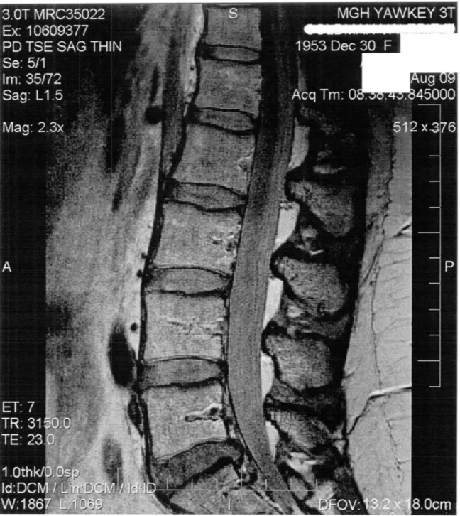
In order to create anatomic 3D model of lumbar spine, MRI has been utilized. Patients are asked to lie supine in a 3 Tesla (3T) MRI machine (MAGNETOM Trio, Siemens, Germany). Using a spine surface coil and a T2 weighted fat suppressed 3D SPGR sequence, parallel sagittal images with a thickness of 1mm without gap, and with a resolution of 512 x 512 pixels were obtained. A field of view of 180 X 180 mm is able to capture the whole lumbar vertebral segment from level L1 to L5. (Fig. 2-1)
Figure 2-1: An example MRI slice of the human lumbar spine from L1 to L5 in the sagittal plane for the purpose to build 3D anatomic model.
3D Spine Model
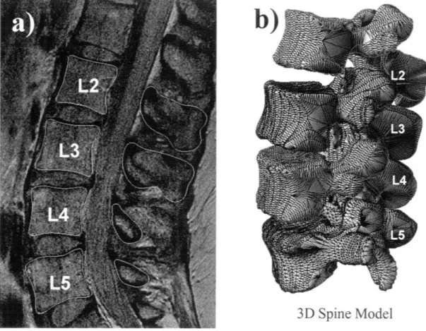
Figure 2-2: a) Contours of the vertebrae bodies was digitized with spline curves give the anatomy information of the lumbar spine. b) 3D mesh model can be generated from digitized contours of MRI layer by layer.
The MR images of the lumbar spine were then imported into a solid modeling software Rhinoceros® (Robert McNeel & Associates, Seattle, WA)to construct a 3D anatomical model of the segments using a protocol established in our laboratory 112. The contours of the vertebrae bodies were digitized manually
based on image intensity using B-Spline curves (Fig. 2-2a). The contour lines were then output into Rhinoceros to construct a 3D anatomical mesh model of the segments. An example of the digitization and mesh is shown in (Fig. 2-2b).
2.1.2 CT
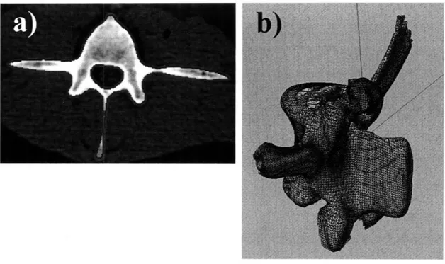
The spine model can also be obtained from CT scanner (LightSpeed Pro 16, GE, Waukesha, WI) using high-resolution axial plane images in the supine position. Images were obtained with a thickness of 0.625 mm and a gap of 0.625 mm, and with a resolution of 512 x 512 pixels. The CT images of the spinal segment were then imported into Matlab® (the MathWorks, Natick, MA). Based on the gradient of image intensity caused by bony structures, Canny edge detection algorithm has been utilized to automatically segment the vertebral bodies 13. The algorithm first smooths the image using a Gaussian filter, and then it computes the gradients from a Laplacian filter. Next, the gradients are reduced by removing non-maximal values. The edges created by the maximal values are further reduced by applying a threshold and examining connectivity. Non-maximal edges connected to Non-maximal edges are kept, while isolated non-Non-maximal edges are removed. Canny edge detection is implemented in Matlab. An example of segmentation is in Fig. 2-3a.
Due to the complex geometry of most anatomical structures and the inherent lack of an edge in biological images, the outlines from the edge detection are manually reviewed. Manual editing is specially implemented at facet joint and at between proximal and distal segments attaches as there are decrease in intensity gradient. 3D anatomical mesh models of the vertebrae were then created from the digitized data. (Fig. 2-3b)
Figure 2-3: a) Automatic segmentation based on canny edge detection for spine CT scan. b) 3D mesh
model constructed from the digitized data.
160
•i:i:i::i:i:ii:i:i: !i i!:ii !ii ii: i
Ilu WJ
Figure 2-4: a) Iterative closest point algorism registers the MRI model with CT model. b) Comparison suggests satisfying geometric agreement with subtle differences.
: : : :: :: :: :: : : : :: : : : : : : : : : : : : :: : : : : :
:-:-:--:---::-:-:::-:---:::--:---':: :-::::: :: ::: ::::::::::::::: :::: :::::::::::::;:::: :::: ::::::-:::::: :-::- :;:::::::::::::::::::::::::::::::::::::: ::: : : : : :::: :: :::: :-:'-::'::i:-'::--:;'::::::-:--- :-::---:::;:----:':---·-'::':-::--- ---:--:: :: ::: : :: : :: : : :: : : :: :: :: : :: : : : : : : :: : ::: ::: : ::: : :: ::: :::::: ; : :::::::::::::::::::::::::::::::::::::::: -::::::: : ::::::::::::::: ::::: ::::::::::::::::::::::::::;::::::: ::: :: ::: ::: ::::: :::::::: :::::::::::i:: ::: : : :::::::::'::: ::: :::: :::: :;:::::::::::::: ::::::i:::::::: : : :: : : : : :: :: : : :: :::::::;::::::::::::: :::::::;::::::::::::::::::::::::: :::::::::::::: : : :: : : :: : : :::::::::::::i::::::i:i::::::: ::::::;::::::::::::::::
- '"-::: - : :: :: : -' :· : :-: : : :: "---::-: ::: ""·''
-:::-2.1.3 MRI and CT model registration
Since CT models have been widely used by researchers to study spine kinematics 16,24,72-79 and CT model is generated from automatic segmentation
based on Canny edge detection, we employed it as a comparison with MR models. The constructed CT and MR image-based models were then mapped together using a customized code implemented in the Matlab based on the iterative closest point (ICP) method 114. About 4000 points were picked from both vertebral body
models. The determination of the optimal shape matching of the two models was characterized by a convergence criterion that using changes in directional derivative of the matching process 114. The average difference between the two
mesh models was calculated to be 0.07±1.1 mm when mapping MR model to CT model. (Fig. 2-4)
2.1.4 Dual orthogonal fluoroscopic
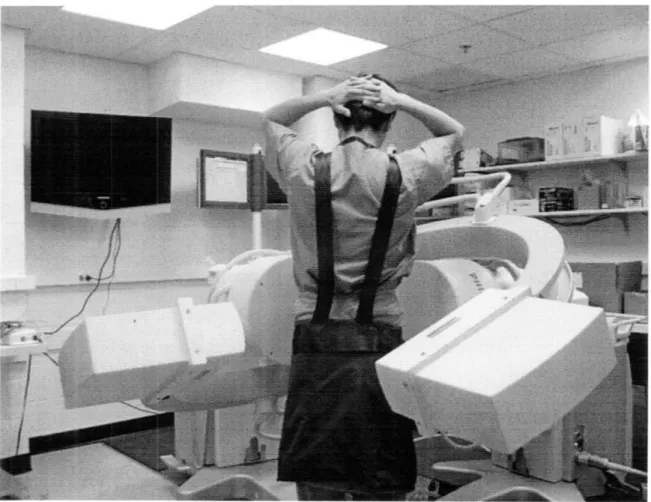
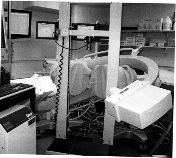
The dual orthogonal fluoroscopic imaging system (DFIS) consists of two fluoroscopes (BV Pulsera, Philips, Netherlands) positioned perpendicular to each other. A subject is free to move within the common imaging zone of the two fluoroscopes. The system is capable to capture real time images of the spine segments simultaneously. A demonstration of the DFIS is shown in Fig. 2-5.
Figure 2-5: Two fluoroscopes positioned perpendicular to each other to capture the spine motion of subjects in the common view port.
The fluoroscopes use pulse snapshots to capture images. The fluoroscopes have a frame rate of 125Hz. 30, 15, or 8 snapshot images per second can be selected that are evenly distributed among the 125 Hz frame rate, which can efficiently reduce the radiation exposure under a high frame rate. The fluoroscope has a clearance of approximately 1 m between the X-ray source and the receiver, allowing the subject to be imaged by the fluoroscopes in real time as he or she
actively performs different maneuvers. With a 1K x 1K resolution of both
fluoroscopes, the total imaging volume can reach up to 30 X 30 X 30 cm3.
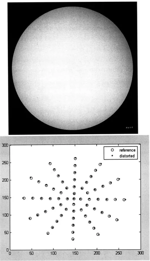
The fluoroscopic images suffer from small amounts of distortion caused by the slightly curved surface of the image intensifier and environmental perturbations of the x-ray. In order to remove "swirl" caused by electro-magnetic disturbance and "fish-eye" from the curved image surface a known grid is imaged and the subsequent image is mapped to the known geometry. A global surface mapping using a polynomial fitting technique adapted from Gronenschild is used to accomplish this 115. A plexi-glass plate with a pattern of holes in concentric circles is used (Fig 2-6).
Figure 2-6: A patterned plexi-plate used to restore the distortion caused by fluoroscope to calibrate
the captured spine image.
2.2 Matching
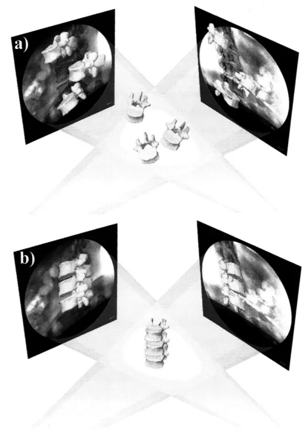
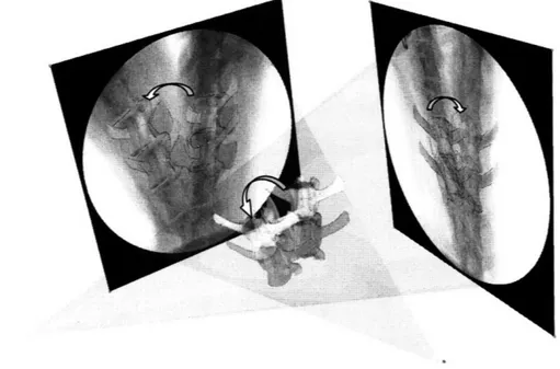
The geometry of the dual fluoroscopes from these tests was reproduced virtually in Rhinoceros. Pairs of fluoroscopic images were placed at the two virtual intensifiers. The CT/MR models of the vertebrae were introduced into the virtual system and viewed from the perspective views of the virtual sources. The 3D models were then independently translated and rotated in 6DOF until their outlines matched the osseous outlines of the fluoroscopic images from the two orthogonal views (Fig. 2-7).
The in-vivo positions of the vertebrae at various physiologic functional weightbearing positions can be reproduced in the Rhinoceros using the 3D models
of the vertebrae and the orthogonal fluoroscopic images 12. The pair of
fluoroscopic images of the spine captured at a specific posture were imported into the modeling software and placed in calibrated orthogonal planes, reproducing the actual positions of the image intensifiers of the fluoroscopes. Two virtual cameras were created inside the virtual space to reproduce the positions of the x-ray sources with respect to the image intensifiers. Therefore, the geometry of the DFIS can be recreated in the solid modeling program. The MR or CT image-based 3D vertebral models will be introduced into the virtual fluoroscopic system and viewed from the perspective views of the two virtual cameras (Fig. 2-7a). The 3D models of the vertebrae could be independently translated and rotated in 6DOF until their outlines match the osseous outlines captured on the two orthogonal fluoroscopic images. This process can be executed using an existing protocol established in our laboratory 6. The software allowed the model to be
manually translated and rotated in increments of 0.01 mm and 0.01. Using this technique, the vertebral positions during in-vivo weightbearing activities are reproduced, representing the 6DOF kinematics at each in-vivo posture (Fig. 7b).
Figure 2-7 a) The 3D model of the lumbar spine segments (from human MRI) were introduced into
virtual system reproduced from geometry of DFIS. b) After manipulate the model in 6DOF, kinematics of the spine can be studied from various physiologic functional activities.
36
i -t i Q ::~:::
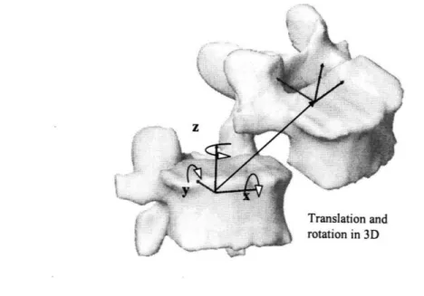
After reproducing the in-vivo vertebral positions using the 3D anatomic vertebral models, the relative motions of the vertebrae can be analyzed using right hand Cartesian coordinate systems constructed at the center of each vertebra (Fig. 2-8). The geometric center of the vertebra body is chosen as the origin of the coordinate system. The x-axis is in frontal plane and pointed to the left direction; the y-axis is in sagittal plane and pointed to the posterior direction; and the z-axis was vertical to the x-y plane and pointed proximally.
The relative motions of the proximal vertebra with respect to the distal vertebra can be calculated at different vertebral levels. Three translations using x, y and z are defined as the motions of the proximal vertebral coordinate system origin in the distal coordinate system: anterior-posterior, left-right and distal-proximal translations. Three rotations using a, P3 and y are defined as the orientations of the proximal vertebral coordinate system in the distal vertebral coordinate system using Euler angles (in x-y-z sequence): flexion-extension, left-right bending and left-left-right twisting rotations (Fig. 2-8).
Figure 2-8: Coordinate system to describe 6DOF spine kinematics, both translational and rotational.
2.3 Summary
While many approaches to study spine kinematics and IVD deformation have been utilized, the quantitative understanding in the human spine under in-vivo physiologic functional activities is elusive. This study will utilize a newly developed, non-invasive imaging technique to quantitatively investigate the intrinsic biomechanics of human spine under physiologic functional activities. The subject underwent an MRI or CT scan to construct the 3D model of lumbar spine. The subject was then imaged by two fluoroscopes in two perpendicular
views simultaneously at physiologic loading motions. MRI models were
introduced into the virtual computer system and were independently translated and rotated in 6DOF until their projection matched the bony outlines of the two fluoroscopic images. The accuracy of this technique will be validated in the following Chapter. The technique will be applied on studying normal human subjects to obtain quantitative data to evaluate in-vivo vertebral motion in the later Chapter. The data will enhance our understanding of spinal pathology and to improve the current surgical treatment methods for spinal diseases that aim at restoring normal spine biomechanics.
Chapter
3
Validation
Limitations of current technology and the complex anatomy of the spine have made in-vivo data limited regarding the motion of the vertebrae under physiologic functional activities. To understand the biomechanical factors that affect spinal pathology, it is critical to accurately determine the spinal structural functions under in-vivo physiologic functional activities. In the previous chapter the idea for employee non-invasive image matching method has been illustrated. The accuracy and repeatability, however requires carefully validation before this method be efficiently applied in spine biomechanics study.
The validation of this technique was conducted in two phases. The in-vitro portion used an ovine spine specimen to validate the accuracy and repeatability of the combined imaging method when used to determine the spine positions in space. Both CT and MR based image models were constructed for the ovine vertebrae in this validation. The second phase was the application of this method to a living human subject in order to determine if the repeatability of the method was
maintained under in-vivo conditions. Only MR model has been utilized to
minimize the radiation dosage to the subject. The goal is to investigate the feasibility for clinical application of the novel technique.
3.1
In-vitro validation
3.1.1 CT and MR models
An ovine lumbar spine specimen, 116 with all the surrounding soft tissues
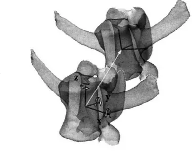
intact was selected and L2 and L3 vertebrae were focused for this study. The spine was CT and then MR scanned according to the protocol in Chapter 2. The contours of L2 and L3 were digitized from both CT and MR images to reconstruct 3D mesh models. The constructed CT and MR image-based models were then mapped together using a customized code implemented in the Matlab based on the ICP method. A local coordinate system was created for each spine vertebral segment model. For the purpose of comparison, the same coordinate system was used by both models. In this study, 6DOF was expressed using the x, y and z axes for left/right, anterior/posterior and up/down translations and using a, P3 and y for the Euler angel flexion/extension, left/right bending and internal/external rotation of the vertebrae (Fig 3-1).
Figure 3-1: A demonstration of local coordinate system established to determine 6DOF kinematics of the ovine lumbar spine.
3.1.2
Dual fluoroscopes section
The DFIS consists of two fluoroscopes positioned perpendicular to each other to capture images of the spine segments simultaneously (detailed in Chapter 2). The specimen was imaged during two tests using DFIS to validate the accuracy and repeatability. First, a gold standard for precisely obtain spine positions was chosen by using an MTS material test machine (MTS Qtest 5,
Minneapolis, MN). The MTS machine has an accuracy of 0.001 mm in translation. The specimen was bounded to the MTS machine which moves vertically upward at 1000 mm/min while dynamic images were taken by the DFIS. (Fig. 3-2)
Figure 3-2: The MTS material test machine was setup to move spine specimen in the common field of view of DFIS to perform a validation test on the accuracy.
This test was aimed to validate the accuracy of the image system in determination of spine translation and speed. In the other test, the specimen was manually flexed to simulate dynamic physiologic flexion-extension motion (Fig.
3-3). Dynamic orthogonal images were taken simultaneously from the
posteromedial and posterolateral directions aimed at the target spinal segment.
Figure 3-3: The specimen was manually flexed to simulate a physiologic motion when two fluoroscopes captured images simultaneously. The test was designed to validate the repeatability of matching spine motion.
The spatial positions of the vertebral bodies during the motion on the MTS machine and the manual flexion-extension activities were reproduced in Rhinoceros software, using the 3D models of the spinal segments combined with the orthogonal fluoroscopic images. First, the geometry of the two fluoroscopes from the two tests was reproduced virtually in Rhinoceros software. Pairs of fluoroscopic images captured at a specific time were placed at the two virtual intensifiers. The CT/MR models of the vertebrae were introduced into the virtual
system and viewed from the perspective views of the virtual sources. The 3D models were then independently translated and rotated in 6DOF until their outlines matched the osseous outlines of the fluoroscopic images from the two orthogonal views (Fig. 3-4). Using this technique, the vertebral positions during various spine activities could be reproduced and represented using the 6DOF positions of the 3D vertebral models in space.
Figure 3-4: After matching the 3D model with 2D orthogonal fluoroscopic images sets from DFIS, the kinematics of the spine was reproduced in space.
3.1.3 Accuracy and repeatability analysis
To evaluate the accuracy of the image matching technique in reproducing vertebral motion, three positions were chosen from the dynamic motion path of the spine that was created using the MTS machine. The exact (to four decimal places) time for each position was obtained from the fluoroscopic radiation impulse data file recorded during the experiment. The distances moved by the MTS machine between the 3 positions were calculated from these time intervals and the known MTS speed. Each of the 3 positions was reproduced 5 times independently using both the CT and MR models and the dual fluoroscopic images as illustrated in the
inset figure in Table 3-1. The displacements of the L2 and L3 vertebrae were calculated between the 3 positions. The translational speed of the vertebra was calculated between the different positions. The displacement and speed data
obtained from the 5 model image matching processes were averaged and
expressed as mean + standard deviation (SD). These data were compared with those of the MTS machine (gold standard) to examine the accuracy of the image model matching method in reproducing the spine translation and speed.
To evaluate the repeatability of using the image matching method to reproduce the dynamic spine motion, five positions along the manual dynamic flexion-extension path were determined 5 times using both the CT and MRI based
models and the corresponding dual fluoroscopic images. The positions and orientations of the L3 with respect to L2 vertebrae were calculated at each selected
flexion-extension position. SD of the 6DOF kinematics reproduced by the 5
image modeling matching processes were calculated. The repeatability in
reproducing the relative positions of the L3 and L2 using the image model matching method was calculated using the average SD of the 5 positions of the spine along the flexion-extension path.
P 2-1 P 3-2 P 3-1 MTS 33.32 mm 33.33 mm 66.64 mm
S
cT
L2
33.52 ± 0.18 33.27
0.09
66.81
0.19
9
E
L3
33.39
0.17
33.15 0.13 66.55 0.14
. MRI L2 33.72 + 0.35 33.14 + 0.32 66.88 ± 0.23 L3 33.23 + 0.25 33.35 ± 0.17 66.72 ± 0.19 MTS 16.67 (mm/s) CT L2 16.77 ± 0.09 16.64 ± 0.04 16.71 ± 0.05 SL3 16.71 ± 0.09 16.56 ± 0.07 16.64 ± 0.03 MRI L2 16.87 ± 0.17 16.56 ± 0.16 16.72 ± 0.06 L3 16.63 ± 0.13 16.66 ± 0.08 16.65 ± 0.05Table 3-1: Accuracy test of the DFIS obtained from comparing vertebrae motion distance and speed prescribed by the MTS machine with the reproduced kinematics.
The displacements of the spine segment between the three positions along the MTS moving path were 33.32 mm (Pl-P2), 33.33 mm (P2-P3) and 66.64 mm (P1-P3), respectively, for both L2 and L3 vertebra. The model matching process showed a high accuracy in determining the positions of the spinal segments (Table 3-1). Both CT and MR image-based models could determine the spine traveling
distances with an absolute mean accuracy below 0.2 mm. The maximal
differences compared to those of the MTS machine measurements were 0.20 mm for the CT model and 0.40 mm for the MR model. Compared with the standard MTS speed of 16.67 mm/s, the CT model reproduced a speed between 16.58 and 16.77 mm/s. The MR model reproduced a speed between 16.57 and 16.87 mm/s. The absolute speed errors were within 0.2 mm/s for both CT and MR models. The accuracy validation using the MTS as a gold standard did not show a significant difference between CT and MR model matching (p=0.2) in determination of traveling distance and speed of the spine.
To evaluate the repeatability, we determined the SD of the 5 matching trials for five positions along the flexion-extension path of the spine segment. The matching process of the dual orthogonal fluoroscopic system was found to be highly repeatable in determining the 6DOF positions and orientations of the vertebrae using both the CT and MR models (Table 3-2). The relative position and orientation of L2 with respect to L3 were determined with a SD less than 0.2 mm using the CT model and 0.25 mm using the MR model. The relative
orientation could be determined to be 0.40 to 0.60 for CT model and 0.60 to 0.90
z c
Table 3-2: Repeatability of reproducing the relative positions of the L3 with respect to L2. The data were averages of standard deviations at 5 positions along the flexion-extension motion path.
3.1.4 Conclusion and discussion
We have developed an imaging matching technique using 3D anatomic vertebral models and DFIS to measure in-vivo spine kinematics. The models were obtained from both CT and MR. Two tests were designed using DFIS to evaluate accuracy and repeatability of this technique. In literature, a few pioneer studies
have investigated spinal vertebral motion using CT imaging 16,23,72-74,79 with
accuracy larger than 1 mm in translation and 10 in orientation. The MR combined DFIS technique is able to determine an absolute mean accuracy within 0.2 mm in translations and a repeatability within 0.3 mm and 0.90 in translations and rotations.
The MR models resulted in similar and sufficient accuracy and repeatability for the purpose of this study compare to CT models either from our study or from
the literature. CT images may facilitate automatic segmentation with
commercially available software. In contrast, automatic segmentation for MR models is currently time consuming. However, the dosage of radiation to which the subjects are exposed when utilizing CT imaging may present an ethical concern for the safety of the individuals being tested. Alternatively, MR model provide us with greater visualization of the ligamentous components surrounding the lumbar vertebra as well as their relation to relevant neurologic structures in this area. Therefore, in order to minimize the risk to the application on living
human subjects involved in Chapter 4 and to enhance our ability to look at the soft-tissue structures of the lumbar spine for further study on pathology, we will use MR imaging exclusively.
3.2 In-vivo validation
Consider the potential anatomic and functional difference between the ovine and human, a validation test was designed to evaluate the repeatability of the model matching method in the determination of in-vivo vertebral kinematics. The image matching method was applied to a living subject (Female, 60 years old). Prior to the initiation of the study, approval by the institutional review board (IRB) was obtained. The subject signed the consent form and was evaluated for the absence of LBP and other spinal disorders.
3.2.1 MR models
The subject underwent an MR scan of the lumbar spine using a surface coil and a T2 weighted fat suppressed 3D SPGR sequence, the same protocol as in Chapter 2 and used for the ovine spine. The 3D MR images were used to construct the 3D model of lumbar spine. A CT scan was not performed to avoid the cumulative radiation dosage on the subject.
3.2.2 Dual fluoroscopes section
The subject was first asked to stand in the dual fluoroscopic image system (Fig. 3-5a) to image the lumbar spine position in the standing weight-bearing
posture. The subject was protected by specifically designed lead vests and skirts. The subject was then imaged in the following sequence of positions: maximal left twist, maximal right twist, and forward flexion at approximately 450. Using the matching method, the relative position of the L2 with respect to L3 vertebra was
reproduced 5 times (Fig. 3-5b). In this study, 6DOF was expressed using the
vertebral displacements along the x, y and z axes for medial/lateral, anterior/posterior and up/down translations and using at, 13 and y for the flexion/extension, medial/lateral bending and internal/external rotations of the vertebrae (Fig. 3-6). The repeatability of this technique to evaluate in-vivo kinematics of the human lumbar spine was represented by the SD of 6DOF translations and rotations from the 5 matchings at each in-vivo position of the spine.
Figure 3-5: a) Dual Fluoroscopic setup for imaging of the lumbar spine position in living subjects during various physiologic functional activities. b) The virtual dual fluoroscopic system is established in Rhinoceros to reproduce in-vivo spine positing using the fluoroscopic images and the 3D vertebral models.
Figure 3-6: 3D vertebral models and local coordinate systems that were used to determine 6DOF kinematics.
3.2.3 Results and discussion
The repeatability in reproducing in-vivo human spine kinematics (the relative positions of the L2 segment with respect to the L3 segment) was shown in Table 3-3 for various in-vivo spine positions. For all the in-vivo physiologic loading positions, the relative translation could be determined within a SD of 0.3 mm, while the orientation could be determined within 0.7', which is comparable with the ovine validation studies from 3.1. The relative position of L2 with respect to L3 was also reproduced using the MR combined DFIS matching method. For example, in forward flexion, the position of L3 with respect to L2 was determined to be -0.79 ± 0.30, 2.23 ± 0.22 and -36.75 ± 0.22 mm in medial,
posterior and distal directions and 3.52 + 0.56°, 3.81 + 0.620 and 4.30
± 0.630 in
forward flexion, left bending and left axial twist. However, these data will be saved and further studied and discussed for the application on human lumbar spine kinematics in Chapter 4.
MRI Position Standing Flexion Twist left Twist right X Y Z a 7Y
L(+)/R(-) A(-)/P(+) U(+)/D(-) FI(+)/Ex(-) L(+)/R(-) L(+)/R(-)
trans trans trans flex bend twist
-0.21 1.2 -36.78 10.29 2.42 1.54
-1.16 ± 0.29 2.86 ± 0.28 -35.71 ± 0.21 7.80 ± 0.46 4.03 ± 0.65 7.02 ± 0.47 -0.79 ± 0.30 2.23 ± 0.22 -36.75 ± 0.22 3.52 ± 0.56 3.81 ± 0.62 4.30 ± 0.63 -1.52 ± 0.29 3.00 ± 0.27 -35.53 ± 0.23 10.89 ± 0.68 7.13 ± 0.56 7.20 ± 0.43 1.13 ± 0.33 3.19 ± 0.24 -35.35 ± 0.18 12.87 ± 0.75 -0.41 ± 0.66 9.98 ± 0.56
Table 3-3: Repeatability of reproducing the relative positions of L3 with respect to L2 using the DFIS when the living subject moved to different positions. The repeatability was represented by mean + standard deviation of the 5 model matchings.
3.3 Summary
Quantitative knowledge of in-vivo vertebral kinematics is instrumental in understanding spinal pathology and for the improvement of the surgical treatment
of spinal degenerative disease. The MR combined DFIS image matching method showed a potential way for non-invasive study in-vivo spine biomechanics under physiologic functional weightbearing activities. This Chapter presented a rigorous validation of the MR (and CT) combined DFIS image matching technique for the non-invasive measurement of spinal motion. The accuracy of this technique was first validated for the determination of vertebral position using an in-vitro experimental setup since a gold standard for vertebral positions was able to be established from MTS machine. The data indicated that the method has accuracy within 0.2 mm in determination of vertebra translations and 0.2 mm/s in translational speed. The repeatability of the method was then examined using both in-vitro and in-vivo experimental design setups. Both the CT and MR image-based model showed similar accuracy and repeatability in the in-vitro tests. The in-vivo human spine experiment using MR model demonstrated a high
repeatability of the method in determination of vertebra within 0.3 mm and 0.60 for translation and orientation.
It should be pointed out that, despite the highly accurate and reliable results obtained during the validation trial, there has certainly been a considerable learning curve during the process of developing this technique. This applies not only to our ability to perform this technique but also to obtain images that are most suitable for the study. It is also significantly more difficult to image in-vivo subjects as motion artifact becomes a concern. We anticipate that there will be a progressive improvement in our ability to obtain fluoroscopic and MR images that were not available at the time of this study. The MR sequences are continuously undergoing adjustment during our ongoing studies in order to improve the resolution of the anatomic features. We therefore anticipate that with further refinement of our technique, coupled with technological advancements in fluoroscopic and MR imaging modalities, the accuracy and reliability of our technique will be improved.
In conclusion, this Chapter examined the accuracy and repeatability of a novel imaging technique in the determination of 6DOF kinematics of lumbar spine segments in a non-invasive manner. The in-vitro validation indicated that this method is accurate in determination of vertebral position in space. Therefore, the MR combined DFIS imaging technique can be a useful tool to investigate in-vivo spine biomechanics, such as to determine vertebral positions and orientations before and after surgical procedures for the treatment of diseased spinal segments in order to evaluate the efficacy of these various surgical modalities in restoring normal spine function. An example of potential applications of this technique includes the evaluation of the effects of spinal fusion or total disc replacement and their effects on adjacent unaffected segments. In the following Chapter, the
method will be applied for the investigation of vertebral motion of living human subjects under various in-vivo physiologic conditions.
Chapter
4
Application on Spine Biomechanics Study
Accurate knowledge of the physiological kinematics of the lumbar spine vertebrae is important to the understanding of the etiology of spinal diseases such
as discogenic lower back pain. This knowledge is also necessary for the
improvement of surgical treatments of spinal diseases that involve either segmental arthrodesis (fusion) or artificial disc arthroplasty (replacement) which may alter the vertebral motion patterns. In-vitro experiments using cadaveric spinal segments have been pursued for decades in order to understand spinal biomechanics 27,117,118. Numerous studies have reported on spine kinematics 15-26
and corresponding deformation 37-43,45-52,119 when a spine segment specimen was
subjected to simulated functional activities.
In order to better understand the biomechanical factors that affect spinal pathology among treated patients, it is necessary to determine the spinal
kinematics in living human subjects. However, the limitations of current
technology and the complex anatomy of the lumbar spine have made it difficult to measure the vertebral motion under physiologic functional activities. In-vivo spinal research to date has mainly concentrated on the measurement of range of motion (ROM) and the evaluation for instability using methods such as bilateral
radiographs, MRI 81,83,84,87,88 CT 73, electrogoniometer 102-105, and
videofluoroscopy 28,120. For example, early research used plain radiographs to
examine the spinal motion of living subjects during flexion-extension positions
121,122. Subsequently, MR imaging technique 123-125 and CT-based methodology 79,126 have been used to measure 3D spinal segmental positions in human subjects
while lying in supine positions.
In the previous Chapter, the MR combined DFIS imaging method has been validated on spine kinematics study. The system was shown to be appropriate for the investigation of lumbar spine motion during weightbearing functional activities. In this Chapter, this technique was first used to determine the 6DOF vertebral motion of the lumbar spine of living human subjects in various weightbearing positions of the body. Then based on the 6DOF kinematics data from these positions, disc deformation was quantitatively studied.
4.1
Experiment setup
Eleven asymptomatic subjects with age ranging from 50-60 years (5
males and 6 females) were recruited for this study. Approval of the institutional review board (IRB) was obtained prior to the initiation of the study. The subjects were evaluated for the absence of lower back pain and other spinal disorders. A
signed consent form was obtained from each subject before any testing was performed.
First, the lumbar segments of each subject were MR scanned with a spine surface coil and a T2 weighted fat suppressed 3D SPGR sequence (same as in Chapter 2 and 3). The subject warmed up for about 30 minutes and then scanned in a supine, relaxed position. The MR images of each subject were carefully examined. Two subjects were found to have presence of early disc degeneration in the absence of clinical symptoms. Additionally, one subject was found to have early scoliosis without symptoms. These three subjects were excluded from further investigation. The MR images of the lumbar spinal segments were then imported into a solid modeling software Rhinoceros to construct 3D anatomical
vertebral models of L2, L3, L4 and L5 of the lumbar spine using the same protocol in Chapter 2 and 3. (Fig. 4-1)
bI
3D Spine Model
Figure 4-1: a) 3D lumbar spine model was constructed from MRI scans. b) The local coordinate systems were established at the center of endplate to study the relative motion of two adjacent vertebral bodies.
Following MR scanning, the lumbar spines of the subjects were imaged using the DFIS. During fluoroscopic imaging, the subject was protected from radiation exposure with appropriate lead shielding. The subject was protected from above and below their lumbar spine by specifically designed skirts, vests, and thyroid shields. A surgeon constantly checked the lead protections to ensure that they did not slip away during the experiment.
The target spinal segments were then exposed to fluoroscopic scanning. The subject was asked to stand and positioned their lumbar spines within the view of both fluoroscopes and actively moved to different postures in a predetermined
sequence: standing position; 450 flexion; maximal extension; maximal left-right
bending; maximal left-right twisting. The two laser pointers attached to the fluoroscopes helped to position the target lumbar spine segments inside the field of view of the two fluoroscopes. At each selected posture, two orthogonal images were taken simultaneously from two directions of the targeted spinal segment. The subject then moved to the next posture under the direction of an orthopaedic surgeon. Care was taken to ensure that no constraint was applied to the hips of the subjects while performing the active motions. During testing, the subject was
exposed to approximately 10 pairs of fluoroscopic projections. The entire
experiment took about 10 minutes. The images were processed in the Digital Imaging and Communications in Medicine (DICOM) and Bitmap file formats.
The in-vivo positions of the vertebrae at various weightbearing body positions were reproduced in the Rhinoceros the 3D models of the vertebrae and the orthogonal fluoroscopic images. First, the geometry of the dual-orthogonal
fluoroscopic system was recreated in Rhinoceros. The MR image-based 3D
vertebral models were then introduced into the virtual fluoroscopic system to be independently translated and rotated in 6DOF until their outlines match the
osseous outlines captured on both fluoroscopic images. This process was
discussed in details in Chapter 2. Using this technique, the vertebral positions during in-vivo weightbearing activities were reproduced, representing the 6DOF kinematics of the vertebrae at each in-vivo posture (Fig. 4-2).