Publisher’s version / Version de l'éditeur:
ASHRAE Journal, 24, 5, pp. 29-32, 1982-05
READ THESE TERMS AND CONDITIONS CAREFULLY BEFORE USING THIS WEBSITE. https://nrc-publications.canada.ca/eng/copyright
Vous avez des questions? Nous pouvons vous aider. Pour communiquer directement avec un auteur, consultez la première page de la revue dans laquelle son article a été publié afin de trouver ses coordonnées. Si vous n’arrivez pas à les repérer, communiquez avec nous à [email protected].
Questions? Contact the NRC Publications Archive team at
[email protected]. If you wish to email the authors directly, please see the first page of the publication for their contact information.
NRC Publications Archive
Archives des publications du CNRC
This publication could be one of several versions: author’s original, accepted manuscript or the publisher’s version. / La version de cette publication peut être l’une des suivantes : la version prépublication de l’auteur, la version acceptée du manuscrit ou la version de l’éditeur.
Access and use of this website and the material on it are subject to the Terms and Conditions set forth at
A smoke control system for high-rise office buildings
Tamura, G. T.
https://publications-cnrc.canada.ca/fra/droits
L’accès à ce site Web et l’utilisation de son contenu sont assujettis aux conditions présentées dans le site LISEZ CES CONDITIONS ATTENTIVEMENT AVANT D’UTILISER CE SITE WEB.
NRC Publications Record / Notice d'Archives des publications de CNRC:
https://nrc-publications.canada.ca/eng/view/object/?id=649cec6e-acd4-4d71-b169-b4199b57922f
https://publications-cnrc.canada.ca/fra/voir/objet/?id=649cec6e-acd4-4d71-b169-b4199b57922f
no. 1038
National Research Council of Canada
c .
2
- -. --
Conseil national de recherches du Canada
A SMOKE CONTROL SYSTEM FOR HIGH-RISE
OFFICE BUILDINGS
by
G.T. Tamura
ANALYZED
Reprinted from ASHRAE Journal Vol. 24, No. 5, May 1982 p. 29-32
DBR Paper No. 1038 Division of Building Research
SOMMAIRE
Un systime d'extincteurs automatiques
5
eau permet de contrgler la quantite de furnee provenant d'un feu et devrait, par cons&quent. 2tre considk6 comme une mesure de protection contre la fum6e. Cependant, dans les bztiments rEcents munis d'extincteurs automatiquesa
eau, les systbmes de de'senfumage constituent souvent une partie du systeme de protection incendie. 11s permettent de rgduire la fum6e avant le d6clanchement des extincteurs automa- tiques et pendant l'extinction du feu. Un systsme d'extincteurs automatiques 'a eau peut aussi r6duire les risques debris de fenEtres en contr6lant la tempErature du feu. Si on suppose que les murs extgrieurs de 1'6tage en feu restent intacts, une gaine de de'senfumage verticale avec un ventilateur en partie supcrieure peut gvacuer la fumge. Cette note fournit les rbultats des essais r6alisb avec un systcme de protection contre la fume'e de ce type pour un immeuble de 34 &ages Equip6 d'un systeme d'extincteurs automatiques 'a eau pour risques faibles.A
Smoke Control System
For High-Rise Office Buildings
A sprinkler system should be considered a smoke control method.
However, in many fire safety systems of sprinklered buildings,
separate smoke controls are included to handle smoke generated
before sprinkler heads are activated. If the exterior walls of a fire floor
remain intact, a smoke shaft with an exhaust fan at the top can
provide effective smoke control.
G.T. TAMURA
MemberASHRAE
A
SPRINKLERSYSTEM controls the amount of smoke generated by fire as well as its spread, and should therefore be considered as a smoke control measure. Separate smoke control systems are often, however, included in the fire safety systems of sprinkled contemporary buildings to handle the smoke generated prior to activation of the sprinkler heads and subsequently from the sprinklered fire. A sprinkler system can also reduce the probability of window breakages by controlling fire temperature. If, as a result, it can be assumed that the exterior walls of the fire floor will remain intact, a smoke shaft with an exhaust fan at the top can ensure effective smoke control.The results reported are of tests conducted on a smoke control system of this type for a 34story office build- ing (Fig. I ) equipped with a light hazard sprinkler system.
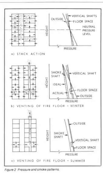
Description of smoke shaft method Figure 2a illustrates pressure and flow patterns caused by stack action in a conventional building when outside temperature is significantly lower than building temperature. The relative po- sitions of the pressure curves for verti- cal shafts, floor spaces, and outside air are indicated. The flow pattern, which can be deduced from the pres- sure diagram, shows a general upward movement of.air so that in the event of fire in a lower floor, smoke will migrate to the upper floors through vertical shafts and openings in the floor con- struction. It may be seen that on the second floor where the fire is assumed to have started, the pressures are greater than those of the vertical shafts at the same level.
G. T. Tamura is a research officer for the Energy and Services Section, Division of Building
Research, Nat~onal Research Council of Canada,
Ottawa, Canada.
ASHRAE JOURNAL May 1982
A smoke shaft with an opening to the exterior at the top maintains pres- sures inside the shaft lower than those of adjacent floor spaces at all levels (Fig. 2b). The positions of the ideal and actual pressure curves of the smoke shaft are shown in the figure, which in- dicate that the pressure differences across the shaft walls are somewhat less than the theoretical values because of friction pressure losses in- side the smoke shaft. Opening a damper in the smoke shaft at the fire floor will extract air from the fire floor, causing pressures on this floor to be less than those of the other vertical shafts (elevator and stair) and of adja- cent floors. The direction of flow, therefore, is from adjacent spaces into the fire floor and from there into the smoke shaft, thus preventing smoke from migrating into stair and elevator shafts. It should be emphasized that this flow pattern will be negated if win- dows on the fire floor are broken be- cause the pressures there will be in- creased to approach those outside, which are greater than the pressures in the adjacent spaces of the fire floor.
In summer, when there is little or no stack action, a smoke shaft is not effective for venting a compartment with a low-temperature fire, but an ex- haust fan at the top of the shaft would make it effective year round as shown in Fig. 2c.
During the early phases of a fire when the temperature in the fire com- partment is increasing rapidly, the air pressure in the compartment also in- creases due to thermal expansion. On- ly when the fire temperature has reached a steady value will the gas cease to expand so that the principal mechanism by which smoke moves out of the compartment is local stack action. The adverse pressure differ- ences caused by the fire are, on the average, in the order of 0.04-0.06 in. of
water (1 0-1 5 Pa) and can be as high as 0.16 in. (40 Pa) of water for a short time, based on test data1j2. Those caused by a fire that is sprinklered can be expected to be less. Adverse pres- sure differences are caused also by building stack action, which depends on outside temperature and building height. The stack pressure difference across the walls of the vertical shaft at any level can be calculated by the following equation:
p, = (1
-
y)Pc (1 ) whereP, = pressure difference across walls of vertical shafts
y = thermal draft coefficient3 and
PC = h g (Po
-
P i )(2)
wherePC = pressure difference due to stack action
h =vertical distance from the neutral pressure level
g = dimensional constant = density of outside air Pi =density of inside air
A pressure difference of 0.10 in. of water (25 Pa) across the fire en- closure, when tested under no-fire conditions, would be adequate to pre- vent smoke from spreading from the fire compartment to adjacent spaces for most high-rise buildings. The re- quired exhaust rate to produce this pressure differential is about 6.0 air changes per hour (ach) for tall office buildings with central HVAC systems4 and about 4.0 air changes per hour with compartmented HVAC systems having no branch air ducts interconnecting floors, except for the outdoor air shaft.
Smoke control system
The test building is conditioned with compartmented HVAC systems. The 29
VERTICAL SHAFTS
1
OLJ T; D FLOOR SPACE E ~- ,-,- ;I NEUTRAL - I .
-L?---
-- PRESSURE ... LU 4 I LEVEL 'L., ,. <>. -. * -. ,-. , . ,.. '-
PRESSURE a ) S T A C K A C T I O N VERTICAL SHAFT b ) V E N T I N G O F F l R E F L O O R-
W I N T E R VERTICAL SHAFT FLOOR SPACE PRESSURE C ) V E N T I N G O F F l R E F L O O R - S L I M M E R ressuFigure 1 Test building (Courtesy of Olympia & York Developments)
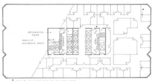
vertical shaft for outdoor air passes through the mechanical room of each typical floor (Fig. 3). The size of the shaft, which is constructed of sheet metal with screwed flange connec- tions and sealed joints, is 54 by 90 in. (1.37 m by 2.28 m). For normal opera- tions, the supply fan at the top me- chanical floor brings outdoor air into the shaft and delivers it through the open dampers in the shaft wall into the mechanical rooms of all typical floors where it is mixed with return air and distributed to the floor spaces with a variable air volume system.
30
The vertical air shaft is designed also as a smoke exhaust shaft with 35,000 cfm (16.5 m3/s) capacity con- nected at the top, and closed multi- blade smoke dampers 32 by 80 in. (0.813 by 2.03 m) in the shaft wall on all typical floors. Under fire conditions, the outdoor supply air fan and the ven- tilation systems are shut down and the outdoor air dampers in the shaft wall of all floors are closed. The smoke darnp- er on the fire floor is opened and the exhaust fan is operated to exhaust smoke from the fire floor into and up the smoke shaft to outside. The central
re and smoke oa tterns
control station to operate the smoke control system is located on the ground floor.
The ventilation systems of the ground and second floors are designed to operate in a smoke exhaust mode to vent these floors in the event of fire. The stair shaft, which serves three parking levels, is also protected from smoke contamination by a pressuriza- tion system. The ground and second floor systems were not tested because the interior construction was too in- complete, although an ad hoc test was conducted on the pressurization sys- tem of the stair shaft serving the three parking levels. Only the results of tests on the smoke control system serving typical floors are reported in the paper.
Test procedure
Tests on the smoke control system serving the typical floors were con- ducted on the 5th and the 15th floors during an evening in March when the outside temperature was 44 F (7OC). All ventilation systems serving the typical floors were shut down, all out- door air dampers were closed, and the smoke exhaust fan was operated with
duction in the pressure differences across the various doors to about 0.060 in. of water (15 Pa). It is ex- pected that opening more than two additional doors in the same stair shaft will have little further effect on the pressures of the vented floor because the stair door opening on this floor will
hlD I M 3 1 t 5 H A k l restrict the rate of air flow from the
stair shaft into the vented floor. Pressure differences measured across the wall of the smoke shaft on several floors are given in Table 1. For both tests, with the 5th or 15th floor vented the pressure differences were greatest at the top and least at the bot- tom. This was dictated by the pressure
* L o c A T I o r d O r S M O K E T E S T S O N T H E l i i H F L O O R losses inside the smoke shaft, and re-
sulted in a greater venting rate on the Figure 3 Plan of typical floor.
15th floor than on the 5th floor. The pressure difference readings indicated that the venting rate of any typical floor would be sufficient to create
the smoke damper open on either the above 0.10 in. of water (25 Pa). It is ex- pressure differences greater than 0.10
5th or the 15th floor. Pressure differ- pected, therefore, that all smoke gen- in. of water (25 Pa) across the enclos-
ences were measured by strain gauge erated by a fire would be exhausted ure of the vented floor. To obtain uni-
diaphragm-type pressure transducers safely to outside through the smoke form venting rate on all floors the
across the doors of stairs, elevators, shaft. smoke shaft should be sized to mini-
washrooms, and the mechanical room; The test was repeated on the 15th mize friction pressure loss. The air
across the ceiling and floor construc- floor with the door of one of the stair velocity inside the smoke shaft was
tions of the vented floor; and across shafts (on this floor) held wide open. 1,080 fpm (5.5 m31s) based on the air
the walls of the smoke shaft on several Measurements (Fig. 4c) indicated that flow rate at the top of the smoke shaft,
floors. Air velocities at the open smoke damper were measured by a hot-wire anemometer traverse and those in the branch duct upstream of the exhaust fan were measured by velocity pres- sure-averaging tubes that were in- stalled during preparations for tests.
The venting test on the 15th floor was repeated with one stair door on this floor held open. The air velocities at the stair door opening were mea- sured by a hot-wire anemometer. A smoke test was also conducted on this floor using smoke candles.
Results and discussion
The results of pressure and flow
Table 1 Results Of Measurements On Smoke Shaft Fifth Floor
AP h~
Shaft Wall Exhaust Rate Shaft Wall Exhaust Rate
In. of In. of
Floor Water (Pa) cfm ach (Lls) Water (Pa) cfm ach (Lls)
31 0.52 129 36,300 7.45 17,110 0.55 137 36,800 7.55 17,350 26 0.49 122 0.54 134 21 0.47 118 0.52 130 16 0.46 116 0.48 121 15 -
-
-
-
20,500 4.22 9,700 11 0.46 116 0.44 110 , 6 0.42 104 0.45 112 5-
- 18,000 3.71 8,530 - - 3 0.41 102 0.46 115measurements with the smoke control system operating to vent the 5th and
15th floors are shown in Figs. 4a and the flow rate at the smoke damper and there was a corresponding pres-
4b respectively. For both cases the opening increased from 4.22 to 4.78 sure loss of about 0.10 in. of water (25
direction of flow is from the stair and ach 23,300 cfm (11.0 m31s) and that Pa).
elevator shafts, washrooms, and floor the pressure differences across the For both tests, the flow rates at
above and below into the vented floor, various doors of this floor decreased the open smoke dampers were about
and from there into the smoke shaft by about one-half to 0.085 in. of water 50 percent of the flow rates out of the
located in the mechanical room. The (21 Pa). The rate of air flow at the open top of the smoke shaft (Table 1); the re-
rate of air exhaust at the open smoke door was 7,400 cfm (3.49 m3ls) or 32 mainder represented the leakage flow
damper in air changes per hour on the percent of the exhaust rate at the into the smoke shaft through leakage
5th floor was 3.71 ach, 18,000 cfm smoke damper; the corresponding av- openings in the closed smoke and out-
(8.53 m31s) based on the floor volume erage air velocity at the open stair door air dampers and in the duct con-
of 290,000 ft3 (8,220 m3) and on the door was 350 fpm (1.8 mls). The same nections. The leakage area of the
15th floor 4.22 ach, 20,500 cfm (9.70 test, except for an open stair door on smoke shaft per floor was estimated to
m31s). Pressure differences on the the ground floor, was repeated on the be 0.30 ft2 (0.028 m2). A smoke shaft
15th floor were greater than those on second stair shaft. The flow rate at the needs to be a relatively air-tight con-
the 5th floor because of the greater ex- door opening on the 15th floor was struction. Field tests5 have shown that
haust rate; but for both tests they were 9,100 cfm (430 m3/s) with further re- a leaky smoke shaft cannot effectively
MECHANICAL ROOM - 7 m \ I 5TH FLOOR 3.71 ach 1. (8.53 rn3/1) SMOKE SHAFT
-
+ , Pa+
a ) 5 T H F L O O R 1: Pa 15Ttl FLOOR 4 . 2 2 och--
19.70 rn3/rli
44 Po b ) I 5 T H FLOOR 15 Pa I 4.78 och (11 .O rn3/1) 18 Po l5TH1
FLOOR1
1
+- C ) 1 5 T H F L O O R - O P F N S T A I R D O O RFigure 4 Results of pressure and flow measurements.
vent the fire floor owing to reduced venting rate at the fire floor caused by excessive pressure losses inside the smoke shaft and extraneous venting of other floors. (The methods of calculat- ing the required size of smoke shaft and exhaust fan capacity are given in
Ref. 6.)
For visual observation, three three-min smoke candles were ignited in the corner office of the 15th floor, as indicated in Fig. 3, with the smoke con- trol system in operation and with all stair doors closed, as for the test con- dition shown in Fig. 4b. The smoke filled the office and drifted into the cor- ridors along the ceiling towards the el- evator lobby where it was held off by
substantial leakage flow through
cracks in the elevator doors into the lobby. Although not verified visually, smoke probably entered the false ceil- ing space and drifted towards the smoke shaft in the mechanical room where it was barely visible owing to dilution.
Twenty minutes after igniting the smoke candle in the corner office, a three-min smoke candle was ignited in the corridor (see Fig. 3), which quickly filled with smoke. When the stair door was opened to duplicate the condition shown in Fig. 4c, the inrush of air from the open stair door cleared the smoke in the corridor in less than a minute. This would assist firefighters in attack- ing a real fire. Smoke was confined to the 15th floor throughout the test, with no evidence of smoke in the stair or el- evator shafts, or in the floors above and below the test floor.
Conclusions
Tests have confirmed that if the ex- terior walls of a fire floor remain intact, as is likely in a sprinklered building, a smoke shaft incorporating the follow- ing features (as found in this test build- ing) can be an effective method of pro- tecting escape routes and floors, other than the fire floor, from smoke contam- ination:
1. Sufficient cross-sectional area to minimize friction pressure losses, so that pressure differences across the smoke dampers are uniform for all floors in order to give essentially the same exhaust rate at each floor;
2. A shaft that includes dampers of relatively air-tight construction to
minimize extraneous venting of floor
I
spaces and thus minimize additional I
pressure losses inside the smoke
shaft;
i
3. Reliable mechanisms that will ensure fully closed smoke dampers until they are required to open to vent the fire floor; and
4. An exhaust fan with sufficient capacity to handle extraneous leakage through the shaft walls and ensure the required venting rate on the fire floor.
Acknowledgement
The author gratefully acknowledges the cooperation and assistance of
Olympia & York Developments,
Mitchell Partnership Ltd., and the Planning and Fire Departments of the City of Calgary during the preparation and conducting of tests. He also acknowledges the contribution made
by R.G. Evans, R.A. MacDonald, and J.
Payer in carrying out the tests.
This paper is a contribution from the Division of Building Research, National Research Council of Canada and is published with the approval of the Director of the Division.
References
1. De Cicco, P.R., R.J. Cresci and W.H. Correale, Report of Fire Tests, Analysis and Evaluation of Stair Pressurization and Ex- haust in High-Rise Office Buildings Per- formed for the New York City Fire Depart- ment. Center for Urban Environmental Studies, Polytechnic Institute of Brooklyn, September 1972.
2. Butcher, E.G., P.J. Fardell and J.
Clark, "Pressurization as a Means of Con- trolling the Movement of Smoke and Toxic
Gases on Escape Routes", JFRO Sym- I
posium No. 4, Movement of Smoke in
Escape Routes in Buildings, Paper 5, Wat-
ford, 1969.
3. ASHRAE Handbook of Fundamen-
tals, Chapter 21, Infiltration and Ventilation, 1977, p. 21.2
4. Tamura, G.T. and C.Y. Shaw, "Ex-
perimental Studies of Mechanical Venting for Smoke Control in Tall Office Buildings", ASHRAE Transactions, Vol. 84, Part 1, 1978,
p. 54-71.
5. Tamura, G.T. and C.Y. Shaw, "Field Checks on Building Pressurization for Smoke Control in High-Rise Buildings", ASHRAE Journal, February, 1981, p. 21-25.
6. Tamura, G.T. and C.Y. Shaw, "Basis for the Design of Smoke Shafts", Fire
Technology, Vol. 9, No. 3, August 1973, p.
209-222. 00
This publication is being distributed by the Division of Building Research of the National Research Council of Canada. It should not be reproduced in whole or in part without permission of the original publisher. The Division would be glad to be of assistance in obtaining such permission.
Publications of the Division may be obtained by mailing the ap- propriate remittance (a Bank, Express, or Post Office Money Order, o r ' a cheque, made payable to the Receiver General of Canada, credit NRC) to the National Research Council of Can- ada, Ottawa, KIA 0R6. Stamps are not acceptable.
A list of all publications of the Division is available and may be obtained from the Publications Section, Division of Building Research, National Research Council of Canada, Ottawa, KIA 0R6.