Publisher’s version / Version de l'éditeur:
Journal of Coatings Technology, 52, 665, pp. 35-43, 1980-06
READ THESE TERMS AND CONDITIONS CAREFULLY BEFORE USING THIS WEBSITE. https://nrc-publications.canada.ca/eng/copyright
Vous avez des questions? Nous pouvons vous aider. Pour communiquer directement avec un auteur, consultez la première page de la revue dans laquelle son article a été publié afin de trouver ses coordonnées. Si vous n’arrivez pas à les repérer, communiquez avec nous à [email protected].
Questions? Contact the NRC Publications Archive team at
[email protected]. If you wish to email the authors directly, please see the first page of the publication for their contact information.
NRC Publications Archive
Archives des publications du CNRC
This publication could be one of several versions: author’s original, accepted manuscript or the publisher’s version. / La version de cette publication peut être l’une des suivantes : la version prépublication de l’auteur, la version acceptée du manuscrit ou la version de l’éditeur.
Access and use of this website and the material on it are subject to the Terms and Conditions set forth at
Adhesion loss due to internal strain
Croll, S. G.
https://publications-cnrc.canada.ca/fra/droits
L’accès à ce site Web et l’utilisation de son contenu sont assujettis aux conditions présentées dans le site
LISEZ CES CONDITIONS ATTENTIVEMENT AVANT D’UTILISER CE SITE WEB.
NRC Publications Record / Notice d'Archives des publications de CNRC:
https://nrc-publications.canada.ca/eng/view/object/?id=ceac081b-93f1-4fed-93ba-c959aa780cea https://publications-cnrc.canada.ca/fra/voir/objet/?id=ceac081b-93f1-4fed-93ba-c959aa780cea
National Research Council of Canada
Conseil national de recherches du Canada
-
-ADHESION LOSS DUE T O INTERNAL STRAIN
by Stuart G. Croll
Reprinted from
Journal of Coatings Technology Vol. 52, No. 665, June 1980 p. 35-43
DBR Paper No. 923
Division of Building Research
L'auteur demontre, experimentalement et theoriquement, comment les defor- mations internes nuisent a I'adhesion des revetements. L'energie de deformation stockee dans un revetement augmente avec I'epaisseur de ce dernier, et, lorsqu'un certain seuil d'epaisseur est atteint, cette inergie suffit i vaincre le travail de I'adhision. Lorsque cela se produit, le revctement se separe sponta- ntment du substrat. L'epaisseur a laquelle se produit le decollement du revitement permet de mesurer directement I'adhision, mesure qui cadre bien avec les rbultats obtenus lors d'essais d'enlkvement et de dtcollement des laques de polystyrene et de polyisobutylmethacrylate utilisees ici.
Adhesion Loss
Due
to Internal Strain
Stuart
G. Croll
National Research Council of Canada*
The manner in which internal strain adversely affects the adhesion of coatings is demonstrated both experimentally and theoretically.
Internal strain energy stored in a coating in- creases with its thickness and, at a certain thick- ness, that energy is sufficient to overcome the interfacial work of adhesion. When that happens, the coating spontaneously peels from its substrate. The coating thickness at which this failureoccurs provides a direct measure of adhesion that corre-
.
lates well with results gained from peeling and pull- off tests on the polystyrene and polyisobutylmeth- acrylate lacquers used here.INTRODUCTION
In'order to be successful, a coating must necessarily adhere to whatever it is intended to decorate or protect. Because a coating may have to withstand many rigors, any strain built into it due to the manner in which it was formed or applied must detract from its performance. Internal strain has been suggested as the cause of adhe- sive failure in a variety of including that of decorative paints which need merely to support their own weight.
Internal strain can weaken the effective adhesive strength of a coating to a value far below its cohesive strength and thus promote the probability of a n inter- facial failure. In fact, certain coatings, which have been shown to suffer a large internal spontaneously peel from their substrates as they dry, if applied in thick films.
The purpose of this paper is to show how internal strain affects the adhesion of coatings and to demon- strate that spontaneous peeling can be used to measure the interfacial work of adhesion and to confirm the results of more conventional adhesion tests.
Essentially, there are two approaches to the question of adhesion: the first attempts to correlateadhesive strengths
tDr. Croll now res~des at 53 Turplns Way, Baldock, Hertfordsh~re, SG7 6LW, England *Materials Sectlon. D ~ v ~ s ~ o n of B u ~ l d ~ n g Research, Otlawa, Canada KIA OR6
with the surface properties of the materials involved; the second describes the performance of systems insterms of stress analysis and various failure criteria. A compara- tively recent development of the latter approach is the energy balance ~ o n c e ~ t ~ ' ~ ' ' which has been successful in analyzing a number of adhesive co~figurations and which will be employed here.
THEORY
The effect of internal strain on the peel and pull-off adhesion tests is analyzed in this section. It is demon- strated that a coating may spontaneously peel from its substrate if it has sufficient internal strain energy stored. A method for estimating this strain energy is also pre-
. ,
sented.
. . .
" .
P'eel Test +Peel testing is one of the most commonly used methods of obtaining a measure of the adhesive qualities of a material. Experimentally, the method is straightforward in comparison with other tests which obtain numerical values for adhesive streogth (as opposed to those which can only rank adhesives or coatings), and the rate of failure can be controlled and readily observed. In prin- ciple, the force required to peel the coating is a direct measure of the energy required to detach that coating. As will be seen later, however, riot all the work expended in a peel test goes to overcome adhesion; there are dissipative mechanisms present.
Diverse aspects of peel tcsting have been subjected to analysis, e.g., the effect of plastic behavior in the mate- rials9 or the degree of bending involved in peeling,'' which demonstrate the limitations of the method.
The energy balance concept adopted here is simple, successful, and it readily incorporates the effect of inter- nal strain. Only the case where the coating is pulled off the substrate at 90' will be considered (Figure 1). Follow- ing
end all,^
the total energy, UT, of the system, peeled at constant speed, isS.G. CROLL
Figure 1-Peel test configuration
where L is the original length of the complete film. The first term on the right-hand side, yb(L -
e
), is the energy that has been expended creating the new surfaces(y is the interfacial work of adhesion) and the second term, F(L -e
), is the potential energy of the applied force, F. The third term t?bt,U~, is the recoverable strain energy stored in the coating owing to the presence of internal strain and assumes that the internal strain is constant throughout the coating, as will be the case in the coatings tested here. UR is the recoverable strain energy stored .&Iunit volume.
The fourth term, UD, is the energy stored in the coating strained by the applied force. One contribution towards it is the energy expended by the peel force in stretching the coating as it is removed from the substrate. This can be readily calculated6 and is much smaller than the other terms in equation (1) and can be neglected. The other contribution is strain energy stored in the peel bend which is assumed to remain constant during the test and therefore does not make a contribution to equation (2). Presumably, if the coating thickness is constant, the peel force is constant throughout peeling and the bend remains a constant size also.
In proceeding with the analysis, if energy is conserved as the adhesive "fracture" progresses then, as the coating is peeled, the rate of change of the total energy, UT, is zero, i.e.,
and the peel strength is given by F
- - - Y - ~ C U R
A more rigorous derivation of this equation can be found in reference (8).
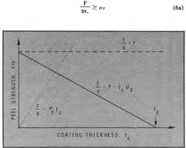
Equation (3) shows that the peel strength decreases, due to the presence of internal strain energy, as the thick- ness of the coating, t,, increases(Figure2). Internal strain is clearly detrimental to the adhesive strength of coatings.
Spontaneous Peeling
The peeling force will vanish for a particular coating thickness, t,, when
Y = tp . UR (4)
i.e., the coating will spontaneously peel from the sub- strate (F/ b = 0) when the strain energy in the coating is just equal to the interfacial work of adhesion (Figure 2). In coatings which are thinner than t,, F / b is greater than zero, and the coatings will remain adhered to the substrate. When t, 2 t,, the coating will spontaneously peel from the substrate (8) as it dries and the internal strain builds up.
Equation (4) might be used to measure y , which is the basic parameter governing the quality of adhesion at the interface and does not depend on interfacial geometry. In the absence of internal strain, y would be directly the peel strength of the coating (Figure 2).
In order to measure y by spontaneous peeling using equation (4), it is necessary to measure U R and t,. The latter can be obtained by direct measurement of the thick- est coating that adheres when dry. UR is the recoverable strain energy per unit volume stored in the coating, e.g., for an elastic material under a onedimensional strain.
where E = modulus of coating
c , = internal strain in coating.
The calculation for typical coatings is given in a later section, but one can see that a calculation of UR and, thus, y should be feasible. In this paper, the results of measuring y by spontaneous peeling will be compared with results from 90' peel tests on polystyrene coatings and pull-off tests on an acrylic coating.
Cohesive Failure During Peel
If the adhesive strength of the interface exceeds the cohesive strength of one of the component materials, then that component will fail, rather than the interface. In the peel test, this amounts to the coating tearing and peeling incompletely from the substrate. Assuming that the coating fails at a stress, O F , determined by the nature of the stress field at the bend and the peel force, the film will fail when
F
-
2 O Fbt, ( 6 4
Figure 2-Graphical representation of the equations governing the 90" peel test
ADHESION LOSS
Equation (6b) is represented in Figure 2 by the dotted line. The intersection of this dotted line and the full line (equation 3) defines a coating thickness above which adhesive failure is the more likely occurrence. In practice, the value of a F would be very difficult to determine and is not attempted here, but cohesive failure will probably occur in coatings of less than a certain thickness.
Pull-Off Test
Figure 3 defines the test geometry. An area of the coating is attached to a rigid cylindrical rod with adhe- sive and pulled off perpendicularly. The stress, a , necessary to detach that area from the substrate is calcu- lated from the force, F, and gives a measure of the coating adhesion. In the absence of internal strain6
where
K
is the bulk modulus of the coating and the other symbols are used as before. One can extend this expres- sion to accommodate the effect of internal strain7As in the case of peeling, the recoverable strain energy counteracts the interfacial work of adhesion. Again, a t a critical film thickness, t,, the strength of the interface,
a, is zero and one expects spontaneous failure of the adhesion when, as in a peel test,
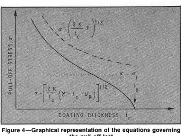
Equations (7) and (8) are represented graphically in
Figure 4 .
It can be seen that internal strain is also very detri- mental to adhesion in this geometry. Again, one can compare the predictions from data gained from spon- taneous peeling with the results of pull-off adhesion tests.
Cohesive Failure During Pull-Off
It can be seen from Figure 4 that the adhesive failure stress in the pull-off test may be very high for thin coat- ings. If the pull-off stress exceeds the cohesive strength of the coating, failure will occur within the coating.
Calculation of the pull-off stress that would result in a cohesive failure is complex. Internal stress (equivalent to the strain) can be represented as two equal stresses at
R I G I D C Y L I N D E R
Figure 3-Geometry of the pull-off adhesion test
Figure 4-Graphical representation of the equations governing the pull-off test
right angles in the plane of the coating. A third stress, perpendicular to these, is the pull-off stress.
If the coating fails in a ductile manner, a yield cri- terion" would be suitable for calculating its cohesive strength in a multiaxial stress state. If the failure is brittle, other methods for calculating the cohesive strength are available.12'"
There is another complication to calculating the maxi- mum pull-off stress resulting in cohesive failure. Adhe- sion of both top and bottom surfaces of a thin coating to a rigid pulling rod and a rigid substrate inhibits lateral contraction of the coating as it is stretched. This has the effect of magnifying the stress that the coating can bear for a given strain. (Appendix A contains a n idealized calculation of this effect.)
A cohesive failure stress, OF, is represented in Figure4 by the horizontal dotted line, which intersects those curves representing adhesive failure. For coatings of thickness greater than that at the intersection, adhesive failure is more likely.
Recoverable Strain Energy Density, U
,
T o calculate the effect on adhesion of internalstrain, it is necessary to estimate the energy stored in the coating due to that residual internal strain. For a perfectly elastic material, the energy stored in the deformed body is that expended in deforming it and can be readily calculated. For a plane stress state (like that of internal stress in a coating), the energy, U, required to deform the body is given by
U = S a x x d e x x
+
J ~ ~+
~J ~ x y d y x y d t ~ ~ (9)In an isotropic coating under internal stress a,, = a,,
(= a), the shear stress T,, is zero, and, thus, equation (9)
can be simplified to
where the strains EX, = cyy = E.
Now in a plane stress situation
S.G. CROLL
Figure S(a)-Estimation of recoverable strain energy by ideali- zation of real stress-strain curve to elastic-plastic form
v = Poisson's ratio of coating, which is generally quite constant irrespective of e .
Thus, the energy necessary to put the coating in a state corresponding to that of its internal strain is
2
u=-
I - u S E(r) dt (12) JE(c) dc = area under stress-strain curve in uniaxial tension up to a strain equal to the internal strain.Knowing the value of internal strain, c,, and the stress- strain curve of the coating would enable us to calculate U. For an elastic material, this would also be the recoverable strain energy density and is given by
Large values of UR will be detrimental to adhesion [equations (3) and (8)], which may occur if either the modulus, E, or the internal strain, c,, is large. Because it is the energy that expresses the effect of internal strain, tensile and compressive internal strains are identical in their effect.
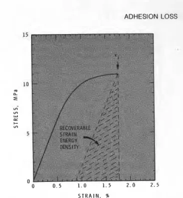
Real coatingsare not elastic materials. Being polymeric, they are nonlinear and viscoelastic. This means that only part of the energy expressed in equation (12) is recov- erable and can be used against the work of adhesion. An accurate calculation of the energy available would re- quire an extensive knowledge of the hysteresis charac- teristics of the coating material and exact knowledge of the strain rate during the production of internal strain and its release during peeling. Therefore, it is proposed to treat the coating as a n ideal elastic-plastic material as in Figure 5(a), where the shaded area represents the elastic (and therefore recoverable) part of the strain energy,
u'.
That area can be calculated, after idealizing the stress- strain curve.Another procedure which gives the same result for U' is to construct an approximate hysteresis loop, from the point on the stress-strain curve which corresponds to c,, by assuming that the first part of the return curve is a straight line parallel to the "elastic" modulus as in Figure 5(b). Since the area of the loop represents the energy dissipated, the shaded part approximates the
Figure 5(b)-Construction of approximate hysteresis loop corresponding to stress-strain curve (full line) strain energy recoverable upon reducing the stress to zero,
u'.
The value of UR can be calculated from either construction.This section has dealt with the recoverable strain energy density in an isotropic coating, which has only a biaxial stress state. Appendix B shows how the sit- uation would be much worse in an adhesive butt joint wherein internal stress (strain) might be present in three directions.
EXPERIMENTAL METHODS AND RESULTS The coatings investigated were clear lacquers formed from either polyisobutylmethacrylate, duPont Elvacitea 2045, (PIBM) or polystyrene, Dow Styrona 685, (PS) dissolved in reagent grade toluene. Values for the internal strain, ~ i , have been reported b e f ~ r e . ~
PIBM e, = 5.8 X lo-' (std deviation 4.4 X PS e, = 1.75 X 10⁻² (std deviation 9.9 X 10'~) In both cases the strain is independent of coating thickness.
Steel feeler gauge stock was used in all cases as the substrate. The usual dimensions for coatings were 12.7 mm X 60 mm. In every case, the substrates were cleaned with toluene and paper tissue before application of a new coating. Environmental conditions were maintained throughout at 23OC (k0.25') and 50% R H (f2%).
Spontaneous Peeling
In order to obtain the thickness at which spontaneous peeling occurred, coatings of varying thickness were drawn down onto the feeler stock and allowed to dry. The thickest coating that remained attached was taken to represent the peeling thickness. Once an adhesive failure crack started, it did seem to propagateinto regions where the coating thickness was lower and one would not have otherwise had a failure. The uncertainty introduced here was eliminated by repeating the test with slightly different coating thicknesses. Another source of error was that the edges of a coating are thinner than the main extent and so tend to inhibit failure. Nevertheless, it did seem possible
ADHESION LOSS
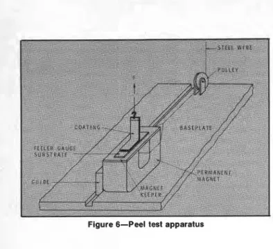
Figure 6-Peel test apparatus
to derive a unique value of peeling thickness, t,, for a particular coating-substrate system
For PS t, = 18 pm (+ 1 pm) For PIBM t, = 480 pm ( 2 4 0 pm)
PS coatings took two to three weeks to dry completely and PIBM coatings of suitable thickness took about nine months. Because repetition of tests on PIBM would be impracticable, the initial batch of coatings contained many more than the initial batch of PS coatings.
The P S coatings were all formed from a 10% w / w initial solution; the PIBM coatings were made by first drawing down a thin coating from a 10% w/ w solution, for good wetting of the steel substrate, and thenapplying a thick layer from a denser solution a day or so later.
Peel Tests
The apparatus on the PTFE baseplate, Figure 6, was clamped to the mobile crosshead of an Instron tensile testing machine. A steel piano wire was attached to the main frame of the testing machine so that the downward motion of the crosshead, which produced the peeling, also moved the magnet (and, thus, the substrate and coating) the same distance across the crosshead in order to keep the peel angle at 90". A PTFE guide was attached to the magnet and ran in a straight groove in the baseplate in order to keep the motion of the magnet and coating, linear.
Using a magnetic clamping arrangement has two advantages. One is that the coating and substrate are eas- ily and quickly attached to the machine, and the second is that positioning the coating so that the peel angle is 90" is also very simple; there are no clamps to undo or realign. A small brass (nonmagnetic) plate and hook were glued to the coating with a filled epoxy resin. In order to pull the coating off, the hood was attached via non- magnetic rods to the b a d cell of the testing machine and the crosshead moved down at a constant speed (2 mm/ min) and the peeling force was obtained as a func- tion of time.
This procedure was quite satisfactory for the thin PS films but the peel test proved to be entirely unsuitable for
PIBM coatings. Thin PIBM coatings had such good adhesion that they either failed cohesively under load or the hook detached from the coating. PIBM coatings that were sufficiently thick to have poor adhesion were too thick and stiff to use in a peel test, so the pull-off test was used to measure their adhesion.
Graphs obtained for (PS) peel force as a function of time show typical slip-stick behaviorI4 as displayed in other peel test work. During the "stick" part of the peel, the adhesive fracture is not proceeding but the load is building up to a value that will cause failure. After the adhesive crack has been initiated, the energy stored in the extended and bent coating is dissipated in propagating the crack and the "slip" occurs, the load falls rapidly and the crack propagates quickly, thus, the rate is not deter- mined by the testing machine. In order to calculate the peel strength, the peak load between the "stick" and "slip" modes was used as it corresponds to the initiation of failure and for that "instant," the rate of peel presumably is defined by the rate of crosshead movement.
Results are plotted in Figure 7. The test was observed throughout to make sure that the peeling occurred nor- mal to the length of the coating. As the proportion of peeled film increased, its torsional rigidity decreased and peeling tended to occur at an angle, or not completely across the coating. The best results often came from the earlier stages of the test.
Pull-Off Tests
Pull-off tests were attempted for both PS and PIBM coatings. The coatings were prepared as before. When dry the substrates were attached to larger plates using a cyanoacrylate adhesive and clamped to the Instron cross- head. The pull-off was effected by attaching 7 mm diam- eter brass cylinders to the coatings using a filled epoxy adhesive. After preparing the epoxy adhesive, it was allowed to stand for one hour before application so that most of the hardener would be reacted and, thus, not af- fect the coating. The glued joints were then left for three days before the pull-off so that the epoxy could harden properly under ambient conditions. Care was taken to ensure that the cylinders pulling the coating off were strictly vertical but elaborate procedures suggested else- where l 5 were not used. The pull-off rate was 1 mm/ min.
Measurement of the pulled-off area was made using photographic enlargements. The results are plotted in
Figure 8 (a) for PIBM coatings and in Figure 8 (b) for
PS coatings.
C O A T I N G T H I C K N E S S . p m
S.G. CROLL
C O A T I N G T H 1 C K N E S S . p in
Figure 8(a)-Pull-off results and predictions for PIBM coatings
Mechanical Properties of Coatings
Films of both coating formulations were made by coating tinplate and freeing the dried films with mercury. The dried films had the same dimensions as the coatings
investigated above (12.7 mm X 60 mm) and were tbin
enough (
-
40 pm) to.ensure complete dryness after abc .t two months. Stress-strain data were obtained with the tensile testing machine mentioned before, using clamps operated by air pressure. In this way, the clamping pres- sure could be varied so that the films did not break in the clamps. There was a n experimental variation of+
5% between the stress-strain data obtained from different films.In order to duplicate the stress conditions in the dried films, the films were incrementally strained and the stress was allowed to relax after each increase in strain to a value sensibly constant after about seven days. The "relaxed" stress-strain curves are reproduced in Figures 9(a) and (b). Also shown in these diagrams is the shaded portion corresponding to the estimate of recoverable strain energy density in uniaxial tension
u'.
For PIBM U ' = 9.89 X 10' J m-'
which represents 100% of the area under the curve up to the internal strain.
For PS U' = 4.78 X
lo4
J m-'I . .
C O A T I N G T H I C K N E S S . pm
Figure B(b)-Pull-ofl results and predictions for PS coatings
which represents 35% of the area under the curve up t o I
the internal strain.
Values of Poisson's ratio adopted are those previously measured4 of 0.4 (PIBM) and 0.39 (PS).
The initial slope of the stress-strain curve defines the appropriate value for Young's modulus, E.
PIBM, E = 0.60 GPa
and Bulk Modulus, K = E
3(1 - 2v)
= 1.0 GPa
PS, E = 1.24 GPa
K = 1.88 GPa
Interfacial Work of Adhesion
Applying the values obtained for U' and v t o equation (14) gives, for the recoverable strain energy density,
PS UR= 1.57 X 10' J m-'
PIBM UR = 3.30 X
lo4
J m-'Now the interfacial work of adhesion can be calculated from equation (4) using the peeling thickness
PS y = 2.8 (f0.5) J m-2 (N m-I)
PIBM y = 15.8 (5 3.3) J m-2 .(N m-'$
Uncertainties are calculated from those of t,, ei and the stress-strain curves. Similar magnitudes of y have been reportedI6 for the adhesion of polymeric coatings on a variety of substrates, although not for the combinations used here.
The interfacial work of adhesion is much greater for PIBM coatings than it is for PS coatings, which means that one must use more energy to detach the PIBM coat- ings. In other words, the adhesion of PIBM coatings t o feeler gauge stock is much greater than that of PS coatings even when the effect of internal strain is elimi- nated. Acrylic coatings adhere well in general to many substrates, while it can be seen that PS would not make a practical coating.
The values of y obtained here were used to predict the strength of peel test and pull-off joints with some success as will be seen later. However, the determination of the critical peeling thickness can be regarded as an adhesion measurement in its own right.
Various methods of measuring adhesion are discussed fully in reference (1 5). Adhesion is a very difficult quan- tity to measure. For example, the often-used scribe type of test ploughs the coating from the substrate and is a complex mixture of adhesive and cohesive measurement. It can only be used to rank coatings. The peel test has
been extensively analyzed and does render a value of y,
but it is best used with flexible coatings which adhere poorly.
The pull-off method also gives a physical value for adhesion but involves attaching cylinders to the coating with adhesive which may affect the coating and its adhesion even before the test is performed. Further, the
ADHESION LOSS
actual test may involve considerable deformation of the coating (and substrate) and the force measured may not represent work done against adhesion, but work done deforming the components of the system.I7
Spontaneous peeling has none of these disadvantages. Strictly, the work of adhesion measured is that of a coat- ing under strain, but the situation is better (simpler) than in other adhesion tests. Experimentally, one needs only to measure the thickness of the coating at various points which is quite a straightforward test needing little equipment. The force which is responsible for detaching the coating is an intrinsic property of the coating and can
be measured separately.
Interfacial work of adhesion, y, is calculated from the product of UR, which is a function of the coating material only, and t,, the peeling thickness.
By using this method one could readily, and quanti- tatively, follow the effect of different substrates or their preparation on y for a particular film(in which UR would be a constant). The best coating for this purpose would be one such as PS, i.e., a thin coating which dries quickly and detaches readily. Alternatively, the peeling thickness would enable one to compare the adhesion of a variety of coatings to a particular substrate.
Pull-Off Tests
The PS coatings gave low results irrespective of their thickness, Figure 8(b). In this case, comparing the re- sults with the theoretical curves calculated using values derived from spontaneous peeling and the mechanical tests yields no information.
On the other hand, data from PIBM coatings show that the theoretical curve presents a reasonable repre- sentation of the pull-off results. The data demonstrate the decrease in adhesive strength (pull-off stress) as the coat- ing thickness increases, due to the presence of internal strain.
As an area of coating is pulled from the substrate, it may not break immediately around its periphery but peel back more coating. Since much less force is required in a peel test to remove a given area of coating than is needed to pull it off directly, one can see that the area which finally detaches may be considerably enIarged by peeling (which decreases the stress apparently necessary).
For a coating to peel, it must be flexible. Bending rigidity, D, increases as the cube of the thickness.
The thin PS films are, therefore, very flexible and will peel much more readily than the PIBM films, which probably explains the low pull-off results. PIBM coat- ings will not show such a great tendency to peel, not only because of their considerably greater thickness but be- cause of their greater intrinsic adhesion. Unfortunately, it is not possible to observe the interface of a pull-off test and the peeling that may occur.
Especially low values for pull-off stress may also be attributed to differences in substrate surface or its prepa- ration. Alternatively, deformation in the PIBM coatings
S T R A I N . W
Figure 9(a)-Uniaxial, relaxed stress-strain relationship for PS films, showing estimate of recoverable energy (- 300 pm thick) may effectively decrease the pull-off stress. For example, the pull-off stress of a rigid cylinder adhering to a deformable half spacc.6^ is much less than that for the same material in a thin layer between a rigid cylinder and a rigid substrate (which is the case assumed here).
Cohesive failure of the PIBM almost always occurred in coatings less than 200 pm thick. This corresponds to a stress of about 10 MPa and is certainly a brittle failure at the test speed employed, and, thus, does not correspond to a point on the stress-strain curve presented in Figure 9(b). Further discussion of the cohesive strength of coat- ings under these circumstances is not within the realm of this paper.
In the absence of internal strain, the 10 MPa cohesive strength line would not intercept the adhesive failure line until a thickness of 320 pm. All coatings thinner than this would fail cohesively if there were no internal strain.
S T R A I N . '70
Figure 9(b)-Uniaxial, relaxed stress-strain relationship lor PIBM films, showing estimate of recoverable energy
S.G. CROLL
The pull-off test seems best suited to rigid coatings and adhesives which are less likely to peel as well.
Peel Tests
It is impossible to carry out peel tests on the PIBM coatings. Coatings that were sufficiently thick to reduce the peel strength to a measurable level proved to be too stiff to bend, as explained previously.
The experimental configuration worked well for PS coatings, however, and the results agree closely with the line representing the prediction from the spontaneous peeling (Figure 7). Loss of adhesive strength because of internal strain is demonstrated very well by these data. Unusually low values of peel strength can be attributed to imperfections in the substrate surface or its prepara- tion. In fact, the excellent agreement of the theoretical line with the higher values of peel strength is somewhat fortuitous. The construction employed to calculate U' from the stress-strain curves (and thus UR and y ) almost certainly gives an underestimate. Consequently, the true value of y for PS under these circumstances should be a little higher. Nevertheless, the results from the peel tests and the spontaneous peeling d o agree very well.
Coatings thinner than 4 p m always tore during the test, so no data could be gathered for very thin coatings.
Provided that the coating is flexible enough to bend, peel testing is more readily performed than pull-off test- ing. Peeling is the method requiring the least force to detach a given area of coating and so is not likely to be complicated by a weaker mode as is pull-off testing (by peeling). Furthermore, visual inspection of the process of peeling is usually possible.
CONCLUSIONS
The results presented in this paper demonstrate that internal strain can have a large and detrimental effect on the adhesion of coatings. Energy stored in a coating by virtue of its internal strain increases as the coating thick- ness increases and, at a ' particular thickness, becomes sufficient to overcome the work of adhesion at the inter- face so that the coating spontaneously peels off. This spontaneous peeling thickness is a direct measure of the work of adhesion for a particular coating-substrate system and might also be used to determine the effect of changing the substrate (or its treatment) or as a means of comparing the over-all adhesion of various coatings. Results from spontaneous peeling might also be used to check the results of other adhesion tests.
Measuring the interfacial work of adhesion from the spontaneous peeling gives results that are consistent with those of other polymer-substrate combinations.
Predictions using the energy balance analysis of adhe- sion agree well with the results from pull-off tests and especially so for the peel tests on PS films. The predic- tions were constructed using values derived from spon- taneous peeling and an approximation of the recoverable strain energy density. Under the test conditions em- ployed, the spontaneous peeling gave the same value for the work of adhesion, y, but in a simpler and moredirect manner than the other tests.
It was found here that one had to use the pull-off test to measure the adhesion of the rigid PIBM film. For the flexible material, PS, the peel test worked well because only one mode of failure occurred (peeling) and it could be visually monitored. In a pull-off test, peeling can also occur and mar the results.
T o be sure of measuring adhesion properly, it must be done in such a way that the adhesive strength of the configuration is significantly lower than the cohesive strength. If possible, the mode of failure during a test should be unambiguous, either peeling or pull-off, not both. Employing spontaneous peeling does eliminate many of the problems of conventional adhesion testing.
ACKNOWLEDGMENT
This paper is a contribution from the Division of Building Research, National Research Council of Can- ada, and is published with the approval of the Director of the Division.
References
( I ) Prosser, J.L., 'Internal Stress Studies," Modern Paint and Coat-
ings, 67, No. 7, p 47-51 (1977).
(2) Bullett, T.R., "Film Structure and Adhesion," J. Adhesion, 4, No. I, p 73-82.
(3) Saarnak, A., Nilsson, E., and Kornum, L.O., J. Oil & Colour Chem. Assoc., 59, No. 12, p 427-432 (1976).
(4) Croll, S.G., "Internal Strain in Solvent Cast Coatings," J O U R N A L
OF COATINGS TECHNOLOGY, 51, NO. 648, p 64-68 (1979).
(5) Croll, S.G., "The Effect of Titania Pigment on the Residual Strain, Glass Transition and Mechanical Properties of a PMMA Coat- ing," Polymer, 20, No. 11, p 1423-1430 (1979).
(6) Kendall, K., "The Adhesion and Surface Energy of Elastic Solids," J. Phys. D: Appl. Phys., 4 , No. 8, p 1186-1 195 (1971). (7) Kendall, K., "Shrinkage and Peel Strength of Adhesive Joints,"
J. Phys. D: Appl. Phys., 6 , No. 15, 1782-1787 (1973). (8) Maugis, D. and Barquins, M., "Fracture Mechanics and the
Adherence of Viscoelastic Bodies," J. Phys. D: Appl. Phys., 11, No. 14, p 1989-2023 (1978).
(9) Gent, A.N. and Hamed, G.R., "Peel Mechanics for an Elastic- Plastic Adherend," J. Appl. Polymer Sci.,21, NO. 10,p 2817-2831 (1977).
(10) Nicholson, D.W., "Peel Mechanics with Large Bend~ng," Inf. J.
of Fracture, 13, No. 3, p 279-287 (1977).
(1 1) Williams, J.G., "Stress Analysis of Polymers," John Wiley & Sons, N.Y., (1973).
(12) Schaeffer, B., "Fracture Criterion for Solid Propellants," Ad- vances in Research on the Strength and Fracture of Materials, p 1145. Fourth International Conference on Fracture, University of Waterloo, 1977, Vol. 3B, Applications and Non-Metals, Ed. D.M.R. Taplin, Pergamon Press.
(13) Manjoine, M.J., "Multiaxial Stress and Fracture," Chapter in "Fracture," Ed. H. Liebowitz, Vol. 3, Academic Press, N.Y. (1971). (14) Gardon, J.L., "Variables and Interpretation of Some Destructive Cohesion and Adhesion Tests," Chapter 8 in "Treatise in Adhe- sion and Adhesives," Vol. 1, Ed. R.L. Patrick, M. Dekker, Inc., N.Y., (1967).
(15) Bullett, T.R. and Prosser, J.L., "The Measurement of Adhesion,"
Prog. Organic Coatings, I , No. 1, p 45-71 (1972).
(16) Chow, T.S., Llu, C.A., and Penwell, R.C., "Direct Determination of Interfacial Energy Between Brittle and Polymeric F~lms," J. Polymer Sci.,: Polymer Phys. Ed., 14, No. 7, p 1305-1310 (1976).
(17) Gent, A.N. and Kinlock, A.J., "Adhesion of Viscoelastic Mate- rials to R~gid Substrates. 111. Energy Criterion for Fa~lure," J.
ADHESION LOSS
APPENDIX A
In the configuration represented by Figure 3, lateral contrac- tion of the coating is restricted by adhesion to the substrate and t o the rigid cylinder as well as cohesion to the surrounding area of the coating. Thin coatings will suffer this restriction most. Assuming that there is no strain allowed in the x and y directions (in the plane of the coating) and that the pull-off stress a, is exerted in the z direction, then Hooke's law gives
1
c, = - [u, - u(u, = 0\)1
E ( A l )
From symmetry a, = a,, and so after some algebra
1- U)
u , = Et, ( I - 2 u ) ( I + u ) ( (A?)
Thus, for a given pull-off strain t , , i.e., movment of the cylinder, the stress is multiplied by a factor depending on Poisson's ratio compared t o the value it would have been if there were no ~ o n s t r a i n t s on the coating area, i.e.,
a , = Et,
If a typical value of v is 0.4, then
(1 -u)
( 1 - 2 u ) ( l + u ) = 2.143
This is a rather idealized treatment, but it does indicate that there may be a significant multiplication of the cohesive strength in a pull-off test. In a real coating the presence of internal strain may make a difference.
APPENDIX
B
If a n adhesive joint were made such that the thickness of the For plane stress the corresponding strain energy is given by adhesive layer was constrained to remain at its original wet
thickness (as well as the area) then internal stress (strain) would 2 EE?
u 2I =- u . , (B4) (Equation 13)
be present in all three cartesian directions.
Assuming that the strain, t , would be equal in all three
directions, then the bulk strain (AV/V) is given by and the ratio of the strain energy in the 3-D (adhesive) t o the
2-D (coating) values is given by (if the same linear strain is pres- -- (B1) ent in both cases)
and the strain energy density, U3, for a n elastic body would be -- U 3 3(1-U) u z - 2 ( 1 - 2 v ) U - - K - =-.-
I - :
("J)
:
3(IE2u) ( 3 ~ ) ~ (B2)I n a typical coating v = 0 . 4 SO
where K = bulk modulus - .
U I
E = Young's modulus -= 2.25
u2
v = Poisson's ratio
therefore, than doubled F o r a n elastic adhesive the strain energy available is more ( v = 0 . 4 ) if the thickness is constrained as well as the area. Consequently, the spontaneous peeling thickness
This publication is being distributed by the Division of Building Re- search of the National Research Council of Canada. It should not be reproduced in whole or in part without permission of the original publisher. The Division would be glad to be of assistance in obtaining such permission.
Publications of the Division may be obtained by mailing the appro- priate remittance (a Bank, Express, or Post Office Money Order, or a cheque, made payable to the Receiver General of Canada, credit NRC) to the National Research Council of Canada, Ottawa. K I A 0R6. Stamps are not acceptable.
A list of all publications of the Division is available and may be obtained from the Publications Section, Division of Building Research, National Research Council of Canada, Ottawa. KIA 0R6.