Design and Experimental Evaluation of an
Autonomous Surface Craft to support AUV operations
by
Robert R. Williams, IV B.S. Aerospace Engineering
Embry-Riddle Aeronautical University, 1996
Submitted to the Department Mechanical Engineering in Partial Fulfillment of the Requirements for the Degree of
Master of Science in Mechanical Engineering
at the
Massachusetts Institute of Technology
February 2007
© 2007 Robert R. Williams, IV. All rights reserved.
The author hereby grants to M.I.T. permission to reproduce and to distribute publicly paper and electronic copies of this thesis document in whole or in part in any now known
or hereafter created., k \ \ N
Signatures of Author
Certified by
Accepted by
Department of Mechanical Engineering January 9. 2007
/
John LeonarcAssociate Professor of Mechanical Engineering Thesis Supervisor
Lallit Anand Chairman, Department Committee on Graduate Theses MASSACHUSET S INSTRJTE
OF TECHNOLOGY
Design and Experimental Evaluation of an Autonomous
Surface Craft to support AUV operations
by
Robert R. Williams IV Submitted to the
Department of Mechanical Engineering on December 2006
In partial fulfillment of the requirements for the degrees of Master of Science in Mechanical Engineering
Abstract
In recent years, there has been a large increase in the use of autonomous underwater vehicles (AUV) for numerous military, commercial, and scientific missions. These include mapping, oceanographic data collection, and search and recovery. The list of the key technologies for AUV research includes communications, power, navigation, design, vehicle tracking and sensor fusion. Despite rapid progress in some of these areas, a number of barriers exists. This thesis offers a novel approach to address these issues by utilizing an Autonomous Surface Craft (ASC) with a wetbay from which to launch an
AUV, including a launch capability. This paper also discusses the fusion of sensors
required by these two vehicles, including computer resources, sonar images, and power.
A new method is described by which an ASC can be tracked through the use of a towed
underwater modem increasing the communication range over two kilometers. This thesis describes how an ASC tracks an AUV by configuring two modems together in a short baseline acoustic array. Results of this tracking show less than four meters of error under difficult real-world test conditions. Discussed are the advantages of transmitting the information obtained in the AUV modem transmission via surface communications. A tracking ASC maintaining close proximity to the AUV allows a larger bandwidth of underwater communication, increasing the flow of information. Expanded flow enables multiple assets to communicate over long-ranges. The impact of these contributions will expand the capabilities of autonomous vehicles.
Thesis Supervisor: John Leonard
Acknowledgements
The people I feel deserve to be acknowledged and thanked are "the do'ers", they not only talk the talk but also walk the walk, following through on their ideas and commitments. These are the people who
influenced me in a positive way by their teamwork and work ethic. If I had a statement that started with "I need" or "I want", these are the first people who would offer their help.
First and foremost, this would not have been possible without my advisor John Leonard. It was his open mind that allowed me to be a part of his team. His diligent management served as an example for me as I focused on my research and development. His remarkable understanding and his seemingly unending patience allowed me to progress smoothly through my research with a minimum amount of drag. John Leonard has been the best manager and mentor I could ever have asked for.
Jacques Leederkerken has the ability to code my thoughts and help expand them. His assistance greatly enhanced the results achieved. He spent many early mornings with me pulling vehicles through the bowels of MIT, prepping the code, and setting-up tests. His on going effort will continue to increase the
capabilities on this thesis topic and improve the results.
Andrew Patrikalakis, was my lab partner and without him testing would not have been possible. He devoted many late nights designing and assembling complex and unique vehicle components. We had many impromptu think tank meetings. He was a great sounding board for me to throw different ideas. His knowledge base and views often differed significantly from mine thus sowing seeds for unique results. One of these results was the use of an array to track vehicles.
Joe Curcio's knowledge and hardware ability were essential during this project. His knowledge helped fabricate and guide me through the development of a new vehicle. His natural ability to adapt and overcome is his strong suit and was used many times during missions to allow testing to continue. His thesis editing effort to help organize my thoughts was invaluable. Joe was able to keep me calm and make me laugh through his never-ending stories of "the trials and tribulations of Joe".
My wife Cheryl, helped in a different way; she kept me sane, she kept me fed, she kept me clothed and
Table of Contents
List of Figures... 11 List of Equations... 13 1 Introduction... ...- 15 1.1 A pp lication ... . 16 1.2 P roblem ... . . 16 1.3 E xam p le M ission... ... 18 1.4 Layout... . .. . ... 19 2 History... 212.1 Amphibious Assault's History ... 21
2.2 Manned Clearance History ... 22
2.3 B each Survey ... 24
2.4 Manned Beach Clearance Techniques... 26
Swimmer Loadout ... 26
Over the Horizon Launch...26
Transports... .. ... 27
G etting To Shore... 29
B each Search ... 30
Extraction ... 30
2.5 B each C learance... 32
2.6 Ship H ull Inspection... 34
2.7 History of A UV navigation and localization methods ... 35
Localization...38
2.8 Sonar ... 40
3. Advances in Design... 43
3.1 Current design... 43
3.2 W et bay construction... 43
3.3 Cooperative Navigation Hardware ... 47
Configuration...48
Transm ission... 50
3.4 Towfish Design... 51
Towfish Body ... 51
Towfish Tailfin... 53
4. Fusion of Sensors and Com ponents ... 57
4.1 Power and Communication... 57
4.2 Sonar ... 59
5. Cooperative ASC/AUV Navigation... 63
5.1 M ethodology... 63
5.2 Array Configuration... 63
5.3 Transmission package... 64
5.4 Transmission Range and Localization Calculations ... 66
5.5 Baseline Ambiguity ... 69
5.6 Environmental Factors in Testing ... 71
5.7 Results... 76
Stationary Array Results ... 76
M obile Array Results... 80
6.1 Summary of Hardware Contribution ... 89
6.2 Future Hardware Research... 90
6.2 Summary of Software Contributions... 90
6.4 Future Software Research... 91
List of A bbreviations... 93
List of Figures
Figure 2.1: A simple beach obstacle- landmine on a tree stump ... 23
Figure 2.2: Dislodged beach emplacements... 24
Figure 2.3: Large tidal zone ... 25
Figure 2.4: Variety of insertion methods... 27
Figure 2.5: Loaded Combat Rubber Raiding Craft... 27
Figure 2.6: Navy SEAL's using a rubber kayak for insertion... 28
Figure 2.7: Navy SEALS performing a high-speed boat cast... 28
Figure 2.8: Navy SEALS performing a high-speed boat cast... 29
Figure 2.9: Navy SEAL performing a high-speed pick-up ... 31
Figure 2.10: Navy SEAL loading a shallow water obstacle ... 32
Figure 2.11: Navy SEAL loading a hedgehog with explosives... 33
Figure 2.12: Navy EOD loading a column mine with Explosives ... 33
Figure 2.13: Jap-Scully loaded with Explosives ... 34
Figure 2.14: Swimmer performing a ship hull inspection... 35
Figure 2.15: SLS Image- USS Monitor of of... 40
Figure 2.16: FLS image- sunk sailboat in Charles river ... 41
Figure 3.1: Wetbay frame and panels... 44
Figure 3.2: ASC front view with bilge keels... 45
Figure 3.3: Kayak with 8020 frame rails ... 46
Figure 3.4: Kayak with bulkheads... 46
Figure 3.5: Wetbay mounted in ASC frame... 47
Figure 3.6: Ranger AUV mounted in wetbay... 47
Figure 3.7: Fixed array with deck CPU and two WHOI Micro Modems ... 49
Figure 3.8: Scout ASC with mobile array ... 50
Figure 3.9: Towfish with WHOI Micro Modem... 52
Figure 3.10: Original and final tailfin design... 54
Figure 3.11: Three towfish during surface checkout ... 55
Figure 3.12: ASC operating off Monterey Coast... 55
Figure 4.2: Blue View Blazed Array (450kHz)... 59
Figure 4.3: Sequence of sonar images with two targets... 61
Figure 5.1: A SC with m obile array ... 64
Figure 5.2: Navigation local ASC references ... 67
Figure 5.3: Reference frame conversion... 68
Figure 5.4: Baseline am biguity... 70
Figure 5.5: Charles River bathymetry top view ... 72
Figure 5.6: Charles River bathymetry three dimensional view... 73
Figure 5.7: Charles River water temperature... 73
Figure 5.8: Charles River water salinity... 74
Figure 5.9: Charles River water sound speed... 75
Figure 5.10: Original tailfin towfish with WHOI Micro Modem transducer... 76
Figure 5.11: Baseline ambiguity solution with stationary array... 77
Figure 5.12: Stationary array initial testing ... 78
Figure 5.13: Stationary array with missed ranging... 79
Figure 5.14: Stationary array with multi-path effect ... 80
Figure 5.15: A SC with array course... 81
Figure 5.16: Actual course one and two from GPS data ... 81
Figure 5.17: Baseline range and bearing results with moving array... 82
Figure 5.18: Baseline ambiguity results in Cartesian Coordinates... 83
Figure 5.19: Final vehicle track in Cartesian Coordinates... 83
Figure 5.20: Difference in acoustic range versus GPS for course two ... 84
Figure 5.21: Difference in acoustic range versus GPS for course one ... 85
Figure 5.22: Difference in acoustic range vs. GPS for course one... 85
Figure 5.23: Raw data intersections on both sides of the baseline ... 86
Figure 5.24: Natural baseline ambiguity constraints ... 87
List of Equations
Equation 5.1 Equation 5.2 Equation 5.3 Equation 5.4 Equation 5.5 Equation 5.6 Equation 5.7 Equation 5.8 Equation 5.9 Equation 5.10 Equation 5.11 Speed of Sound ... 67Range from Time ... 68
Angle from Range Intersections ... 69
Target Location in ASV Reference Fram e ... 69
Rotation M atrix ... 70
Target Location in Global Reference Fram e ... 70
Baseline Side Point to Point Average ... 72
M axim um Vehicle Velocity Lim it ... 72
M oving Baseline Average ... 73
Standard Deviation... 73
1 Introduction
The Office of Naval Research (ONR) has defined five major priorities encompassing the design criteria before autonomous vehicles can be incorporated into the naval fleet for wide use [1, 2]. An autonomous platform must be able to have an autonomous dynamic control during missions, perform 1) reconnaissance, 2) surveillance, 3) target acquisition/ designation, 4) beach survey and 5) battle damage assessment. An Autonomous Surface Craft (ASC) with its complement of sensors, can fulfill a number of these roles due to its diversity and adaptability to the environmental requirements. Additional priorities set forth are a robust package that can operate in multiple environments and conditions. Fusion of the ASC's and Autonomous Underwater Vehicle's (AUV) capabilities allows for a broad range of underwater environments to be reconnoitered. Underwater reconnaissance and surveillance missions are primarily preformed through sonar image processing. The result of these processes gives the manned operator a map specifying the locations of objects of interest in the surveyed area. Surface surveillance can be performed with off-the-shelf visual augmentation packages. Cameras would record beach and hinterland information that can be broadcast real-time through RF communications. The communication package can be a low-power commercial 802.11 Wi-Fi communication link or a more robust low-probability-intercept/low-probability of detections (LPI/LPD) military system. The ability to feed this all through a robust mission-planning package of following waypoints and performing tasks is essential and greatly simplifies the efforts required to operate the system [20].
Technology has necessitated a shortened reaction time for a country if it is to be effective in engaging its military power in defense against an invasion. Deploying ground forces effectively and safely is of great concern. Designing equipment to counter enemy defensive weapons prior to the deployment of ground forces, specifically for an amphibious assault, provides the motivation for this thesis. Hopefully, these efforts will reduce the causalities of our countrymen in future littoral conflicts.
1.1 Application
The idea of using autonomous vehicles to search a given area and to return disclosed information has existed for many years. The United States Department of Defense has many remotely operated vehicles. Landbased remotely operated vehicles, such as Talon, can be manually driven to objects of interest and, by using visual camera technology, can record images allowing an operator to classify objects of interest after the mission [3]. Many airborne assets exist, such as the Predator and Global Hawk, which have extensive sensor payload for tracking and prosecuting targets [3]. They also have an ordnance payload and can operate as the sole source for an offensive engagement. The Navy uses the Super Scorpio for salvage operations in deep water, and recently has used a Semi-Autonomous Hydrographic Reconnaissance Vehicle (SAHRV or the civilian version
REMUS) for clearance operations in Al-Basrah Port, Iraq [11]. These are all important
advancements toward fully autonomous operations but they are labor intensive. They require an extensive infrastructure to operate. In contrast, operation of an autonomous vehicle reduces the manpower needed to prosecute the same mission by requiring minimal configuration and is designed for no user interaction once initiated. As robots evolve into autonomous vehicles, their abilities to calculate the correct path must expand exponentially. They are limited by the ability of the programmer to ensure that all environments they can enter are accounted for in the operating software. This configuration for environmental information would be uploaded as to what course to follow to fulfill the mission requirements. The autonomous vehicle then determines the correct path to complete the mission.
1.2 Problem
The Autonomous Operations for Future Naval Capabilities (AOFNC), a recent research program of the Office of Naval Research (ONR), addresses autonomous operation gaps in the ability of the United States Navy Forces to conduct successful autonomous missions. The vision of AOFNC is to dramatically increase the autonomy, performance,
and affordability of the autonomous vehicle systems. To meet this charter, four major vehicle categorizes were determined to cover all current autonomous realms: Unmanned Aerial Vehicles (UAV), UAV Propulsion, Unmanned Undersea Vehicle (UUV/AUV) Technology and Unmanned Ground Vehicle (UGV) Technology [2]. The AOFNC-designed products, both hardware and software, are to be capable of transition into the fleet operation forces with minimal effort.
Of these categories, the AUV technology project addresses the capability to perform
missions with AUV assets allowing United States Navy Forces to expand their sphere of influence and to mitigate the inherent risk of operating in littoral waters. The Navy AUV's Master Plan [1] identifies seven key missions that can be fulfilled by autonomous programs: 1) Intelligence/Surveillance/Reconnaissance (ISR), 2) mine countermeasures (MCM), 3) oceanography, 4) communications/navigation aid (C/NA), 5) anti-submarine warfare, 6) weapon platform engagement, and 7) logistics supply. This paper will discuss four of these missions: ISR, MCM, oceanography, and C/NA. The goal of ISR is to provide the ability to rapidly survey selected areas using networks of small AUV's, performing functions such as mine hunting/neutralization, underwater object location and recovery, and hydrographic/bathymetric surveys [2]. Locating mines in littoral waters is the primary purpose of sonar equipment. Oceanography, such as depth, temperature, wave height and duration information is also recorded. The surface C/NA is to provide a communication/navigation relay for other underwater vehicles operating in the immediate area and is expected to serve as a gateway for an autonomous underwater communication network. This is also the root of the research performed in this thesis, with respect to localization of an underwater vehicle from a single surface asset. Sensor fusion between two waterborne autonomous vehicles to increase the capability of both is advantageous. This combination is force multiplier, where the abilities of each vehicle are far surpassed
1.3 Example Mission
An example of how an ASC used during a tactical situation is; imagine a U.S. ground assault force aboard ships located over the horizon, off the coast of a terrorist-supporting country. To initiate a predawn amphibious assault, the ships launch a group of autonomous surface vehicles at dusk. Each of the ASC's travels at five knots to a unique target, determined from a-priori reconnaissance maps. As ASC's navigate toward shore, they employ on a small motor with an electrical alternator to keep their batteries fully charged. Prior this infiltration, the motor is shutdown to minimized noise and batteries maintain power to operate the ASC's and AUV's systems. The ASC sends a real-time surface Forward-Looking Infrared (FLIR) imaging system, along with wave period and wave height information from gyro rate calculations to the command and control ship through a SATCOM/Iridium communication package. This combined with the forward-looking sonar image from the AUV payload forms a substantial situational awareness for those in control and can assist in their formulation of a plan of attack for the follow-on beach assault.
The ASC utilizes the sonar of the AUV mounted in its wetbay to determine its position in reference to an uploaded reconnaissance map of the underwater domain. From this result, the ASC can adaptively vectoring itself to its pre-designated target. It begins to flood ballast tanks decreasing its surface signature. As a specific target comes within range, the AUV receives a final surface navigation fix and launches from the ASC. The un-tethered AUV dives on a target intercept course, followed by the ASC navigating a shadow course. A communication conduit is maintained between the two autonomous vehicles using underwater acoustic communications (ACOMMS). As the AUV makes its way toward the target, it transmits a unique ACOMMS signal, which is received by the
ASC along an acoustic array. The ASC calculates the position of the AUV from the ACOMMS signal. If the AUV course exceeds an error corridor toward the target, the ASC will transmit an error correction for the ALJV to amend any underwater navigation
error, thus enabling the AUV to properly proceeed toward the target. Once the AUV sonar acquires the target, its terminal guidance code is enabled.
With the AUV at the target, it begins a detailed transmission of the ten most recent sonar images to the ASC. The ASC uses this transmission to accurately determine the AUV's final position. The ASC transmits to the command and control, the location and final images used for target acquisition, and classification. The command and control can then identify, and verify the target as necessary . If the command and control deems a change of target is required, the new mission would be relayed through the ASC to the AUV. When the AUV mission is complete and remains with the target, the ASC returns over the horizon for reuse if required.
1.4 Layout
This thesis discusses the initial steps toward the realization of a new paradigm for an
ASC and an AUV to interact cooperatively while performing a mapping and surveillance
mission. The following chapters will define how four of the seven missions as outlined
by ONR vision of the future for Naval work with AUVs.
Intelligence/Surveillance/Reconnaissance (ISR) gathering is accomplished using low cost forward-looking sonar underwater. Through sonar image detections, objects that meet predefined MCM criteria can be located. Oceanography characteristics can be determined from both autonomous platforms using sensors to determine wave height, wave period, water temperature, and other data. The Communication/ Navigation Aid
(C/NA) is where the true fusion of sensors takes place. It is important for the two vehicles
not only for maintaining an accurate position of the AUV but for also sending terminal
AUV guidance and returning final images to planners for detailed real-time analysis for
future missions.
Chapter Two discusses the history of amphibious warfare as it pertains to methods used for clearing a safe passage which will allow troops to penetrate from the ocean onto the shore. Discussed are current techniques used by the US military to clear a beach of underwater threats. The capabilities of past and current vehicles are discussed: can they operate as efficiently? In addition, this chapter discusses the manned assets which are available today; and the Navy's is interest in replacing them with autonomous vehicles to fulfill the requirements.
Chapter Three presents a novel approach for docking an AUV into an ASC with a launch capability. We present the design of the RUSSO (Remote Underwater Surveillance and Support) ASC, a robotic surface craft designed for autonomous deployment and operation of AUVs. The design has been instantiated as an extension of the Scout ASC developed
by Curcio et al. at MIT [7], [12]. We use the Nekton Ranger as the target host AUV[6].
This chapter also reviews the hardware design and provides details of key subsystems, including autonomous launch, modular bay, and hull modifications.
Chapter Four focuses on the sensor fusion of the design, interaction of sensors including the power and communication between vehicles systems. In addition, this chapter describes extensive field trials using a Scout ASC equipped with a Blazed Array Forward Looking Sonar (FLS) for mapping experiments.
Chapter Five addresses the cooperative ASC/AUV navigation problem, presenting a new approach to tracking an AUV from the surface, using standard Woods Hole Oceanographic Institute (WHOI) Micro Modems in a short baseline configuration [8]. Extensive experimental results are reported. (This algorithm has been implemented in close collaboration with MIT EECS Ph.D. candidate Jacques Leedekerken.)
Finally, Chapter Six summarizes the contributions of this thesis and suggest directions for future research. Exciting possibilities for further extending the RUSSO/Scout ASC concept including surface concealment, satellite communications, launch of a swarm of sensors, and creation of long duration mobile gateway.
2 History
The Office of Naval Research has an interest in the welfare and safety of sailors manning the front lines. It is commissioned with advancing the technologies available for deployment into any theater of operation. Today's escalation of terrorist activities poses great challenges to the men tasked with protecting American values. The capabilities of these foes and the countries which harbor them bring a significant military threat to the Unites States. This enemy has a history of unprovoked violence towards others and is currently challenging all of the free countries of the world. As a result, the United States has been constructing equipment to decrease the risk to the warfighters. The United States military forces have been deployed into foreign countries in an effort to reduce the threat these countries impose to the free world. Gaining access to these countries is the first step. Very few countries are landlocked. However, many defiant countries have allies or neutral neighboring countries. Neighboring countries in some cases play a neutral role fear of retaliation and concern for safety of their citizens. Their neutral role typically precludes the use of their land as a passageway by international forces. If a defiant country is surrounded by friendly or neutral countries but has seashore access, two options exist for gaining entry: amphibious and or airborne assault.
2.1 Amphibious Assault's History
The root mission of sea warfare for naval forces is defined with a primary mission of transporting ground offensive forces into a position where they can project military power ashore and engage the enemy. In previous eras amphibious assaults stood as the preferred method to deploy troops onto foreign land. In modern times, this still remains true even though airborne assaults have gained popularity with the expansion of air power. In the past and present, the bulk of forces are landed from the sea. They allow for a large amount of warfare equipment to be brought ashore in a short period. Enemies familiar with amphibious warfare fortify beaches with defensive weapons: mines,
barricades, impingements, and beach artillery emplacements are set to block any advances by foreign countries through their shores.
Historically, the first known amphibious assault was recorded in 490 BC during the Battle of Marathon, when the Persians attempted to conquer the Greeks. The vessels in the assault force numbered approximately 600 while the number of soldiers involved were 40,000 [3]. The losses sustained by these forces were high due to poor planning of the amphibious assault. Due to sea conditions encountered during the invasion, more then half of the troops never made it ashore. Rough seas forced the ships onto rocky shores destroying the ships and forcing the men into the hostile waters. When the remaining armada returned to sovereign soil, they had less then 200 ships surviving and only 30% of the men.
Amphibious assaults have been a part of American history. George Washington's crossing of the Delaware in 1776 won a decisive victory over the British at Trenton. This victory has been singled out as having reinvigorated the American Revolution spirit. History refers to this as the turning point in the revolution. In the Battle of Normandy, an estimated three million troops crossed the English Channel into occupied France. In fierce fighting, the allies broke through the German lines and began to win the war. The Battle of Normandy was the turning point in World War II. Naval power was also used extensively in other US conflicts such as Korea, Cuba, and Vietnam.
2.2 Manned Clearance History
Manned underwater obstacle clearance has occurred throughout history. During the Battle of Normandy, United States Navy swimmers were called on to conduct pre-assault hydrographic reconnaissance of the objective beach areas. Swimmers were launched from submarines and ships, under the cover of night. They swam ashore to locate and map obstacles; in addition, they mapped the beach gradient from twenty feet deep to the shore. Once the data were composed, follow-on clearance missions were sent before and during the assault, sometimes in broad daylight, to remove the mapped obstacles from the
landing area. The swimmers cleared a number of enemy beach emplacements prior the arrival of assault forces and continued to clear obstacles throughout the battle thus increasing the landing beach area. Their only protection from enemy fire was naval gunfire support which was not accurate enough for defeating targets within rifle range. The result was personal losses of over 70% on some beaches but the number lives the surveying forces saved was substantial. The overall job of these men has remained the same over the years; they had been called Naval Combat Demolition Units (WWII), Scouts and Raiders (Korea), and Underwater Demolition Teams (Vietnam). Today they are called Navy Sea Air and Land Commandos (SEALs), a small tight group of men ready to take war to the enemy, to be employed when diplomatic relations fail. In addition to these forces, Navy Explosive Ordnance Demolition (EOD) has also been used to ensure beaches are clear of enemy threats.
Countries know being invaded from the sea is a high probability. In an attempt to discourage amphibious assaults, they fortify their defenses by placing obstacles in the littoral waters. Wide varieties of fortification obstacles have been used, and have been made of metal, concrete, wood, and composites. Some are very elaborate setups of steel structures with buttress and inverted arches to impale approaching landing craft. More simple designs such as a wooden pole angled toward the beach approach are effective as in Figure 2.1.
Some are made exclusively to house explosives (mines); they have a variety of different detonation methods. Three major types of mines can be deployed: bottom, water column, and free-floating. Bottom and water column mines are typically placed in close proximity to the beach, while free-floating mines are unrestrained and thus can be encountered in seemingly countless places. The capability to remove these obstacles with minimum risk to troops is of great interest.
2.3
Beach Survey
An up to date and accurate map is required to effectively prosecute any beach clearance mission. Beach defenses are typically a mixture of different types of obstacles; not all have explosives and not all are made of steel. Properly deployed defenses will defend a given beach independent of the current and tides.
Beach defenses are deployed usually in some arranged fashion. However, the exact location of an obstacle in the surf zone varies as the forces of the tides move them throughout the surf and shallow water. Sometimes the obstacle locations vary every time a tide occurs. As shown Figure 2.2, large surf dislocated these concrete-weighted steel structures onto a rock jetty.
The result is that a beach survey has a limited life to remain accurate; water conditions, such as extreme tides, currents, or storms, continue to modify the seafloor, particularly in the littoral waters. Obtaining an accurate map of a littorial area is often difficult to do; some areas have a twenty-foot vertical difference between low and high tide, which can cause the waters to recede a normal beach gradient by more then two miles, as shown in Figure 2.3.
Figure 2.3: Large tidal zone
Performing a manned survey on this beach would be difficult to do, due to the shear size of the beach area. A prior survey of tides and current to ensure the validity of the proposed beach is necessary for a beach landing.
2.4
Manned Beach Clearance Techniques
This sub-section contains a detailed description of manned clearance operations; it is intended to give the reader a background of current capabilities and can be passed over at reader prerogative. The current techniques of all military manned clearance detachments are similar to one another and are described below. Significant detail is expounded here because it is important to understand what an autonomous vehicle (and every autonomous vehicle designed for Navy for use in littoral waters) is supposed to replace.
Swimmer Loadout
A swimmer loads out for a beach clearance mission with minimal gear. The reason is that
loose gear slows forward progress. He has the water distance and surf to protect him from the enemy and conceal his movement. A swimmer will use a wetsuit to combat water temperatures and increase his duration; it is also good for protection against coral, rocks, barnacles and other sharp objects underwater. Other standard items include mask, knife, gloves, fins, and explosives to leave behind.
Over the Horizon Launch
The first step is getting to the beach. Before insertion of swimmers, a large Navy vessel will dispatch smaller vessels from over the horizon at an infiltration point. Small vessels including surface rubber boats and mini-submarines are used. Submarines such as the
SEAL Delivery Vehicle (SDV) are launched from a variety of naval platforms. An
SDV's can enable swimmers to travel long distances in shallow water while remaining undetected. Other times a small boat is launched underwater. A stowed rubber boat is worked free by swimmers on the deck of the submarine. The boat may have engines and other equipment lashed inside it ready for use once it reaches the surface and is inflated.
A variety of insertion methods are shown in Figure 2.4. All swimmers are wearing the
standard gear (note mask, knife, and fins). Some swimmers are also using an open circuit compressed air system; these are not used near the shore and will be left on the ship. Pulmonary air embolisms have occurred in divers when the large sea surf cycles over them while searching the bottom.
Figure 2.4: Variety of insertion methods
Transports
Some missions call for fast raids into small shallow harbors. Combat Rubber Raiding Craft (CRRC) are used as a high-speed motorized transport for OTH insertion of swimmers into a hostile beach area. These have maximum payload of six men at up to 20 knots, as shown in Figure 2.5.
Special rubber kayak's have been used in the past and can be employed as a speedy human power shallow-draft transport. The two-man kayak can be carried and paddled easily for long distances in shallow water, as shown in Figure 2.6.
Figure 2.6: Navy SEAL's using a rubber kayak for insertion
Another manner in which to enter the water in a short period is a high-speed boat drop off, as shown in Figure 2.7. This allows multiple swimmers to arrive at a beach expeditiously.
This allows a boat to decrease its chance of enemy contact by staying at speed. Men climb from the drop-off boat into the rubber raft towed alongside, ready to drop overboard on a given signal. They are dropped off about every fifty feet along a straight line a few hundred yards from shore. They will return to this line later to be picked up by the same boat. As fast as the two men in the rubber raft drop off, their places will be taken by the next pair to be "delivered." The first man is given a signal to drop and the rest follow as fast as possible.
Figure 2.8: Navy SEALS performing a high-speed boat cast
Figure 2.8 shows the actual dropping of swimmers to perform an initial inspection of a beach. The swimmer entering the water on the right is dressed for warm-water work.
Getting To Shore
Insertion methods vary and are dependent on the capabilities of the enemy. Under the cover of night, insertion methods include: small surface craft, high-speed drops from RHIBs, Zodiacs with small outboard motors, small inflatable boat under paddle power, kayaks, airdrops, and others. At two miles out from the shore, swimmers deploy to swim the remainder of the way. The speeds at which they can swim are directly dependent on the surface conditions. Sea State III and above greatly hamper forward progress. In all
cases, the overall time personnel can be in the water is limited by the onset of hypothermia.
Beach Search
The area that can be surveyed in one night is greatly dependent of environmental factors. How much and how fast a beach can be surveyed is proportional to the number of swimmers, the range of visibility, the extent of illumination and sea conditions. A typical method of searching for underwater obstacles is called the "parallel beach survey" technique. Swimmers form a line parallel to the shore at an interval determined by sea conditions. The swimmers on each end of the line ensure the swimmer line is parallel to the shore. These two swimmers position themselves by using GPS and take bearings to known positions to triangulate a fix. Their task is to maintain a steady position for the rest of the swimmers to use as a reference. The remaining swimmers, using only visual clues space out evenly between the two ends. When the lead end swimmer is satisfied with the form and separation of the swimmer line, he signals for them to dive. The swimmers then submerge and visually search a predetermined area and note the depth. When a swimmer surfaces he records his findings along with the depth on waterproof paper. Then the swimmer line moves perpendicular to the shore and the swimmers dive again. This process is repeated until the desired beach has been searched.
Extraction
Once the swimmers' mission is completed they proceed for recovery. For a high-speed pick-up, the swimmers swim to the predetermined recovery area. They form a straight line horizontal to the beach, with some separation. A small rubber boat is towed along side of a high-speed boat. In the small rubber boat, an individual holds a large rubber loop over the side. This loop is used to snare and snatch the swimmer from the water. As a boat approaches, the swimmer extends his arm to be hooked and is snagged by the loop, as shown in Figure 2.9. The velocity of the boat pulls the swimmer from the water and literally flips him into the boat. As he quickly moves out of the way, another swimmer is
snagged until all swimmers are recovered. Speed of the pick-up is important as it helps flip the swimmer into the boat.
Figure 2.9: Navy SEAL performing a high-speed pick-up
The most important aspect of the pick-up falls directly on the shoulders of the high-speed boat's coxswain. A pick-up is successful only if all swimmers are snared on the first pass. If the pick-up craft is detected, it is often moving fast enough that most enemies fail to realize that a swimmer pick-up is taking place. If a swimmer is missed, the boat has to make a second run and that increases the chance of detection and as well as being engaged by weapons. Therefore, it is the responsibility of the boat coxswain to maneuver the boat down the pick-up line, close enough to the swimmers so they can be snared, and at a speed that will allow each swimmer to be pulled into the small boat before the boat reaches the next swimmer. Timing, speed, and boat location are critical to the success of this operation. This method greatly reduces overall recovery time and any danger to the boat from enemy fire. However, many swimmers returned from these recoveries with black and blue bruises covering the entire inside of the arm, caused by the impact of the pick-up sling.
2.5 Beach Clearance
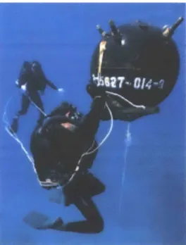
When a beach has been designated for use in an amphibious assault, missions are performed to remove any objects that were found during the beach survey. On this mission, a swimmer line is formed again, with each swimmer carrying a bag of explosives. The end of the line swimmers attempt to align themselves in the same position as the previous survey, and an underwater search is performed again. Once a target of interest has been located such as this steel hedgehog in the shallow surf zone, the swimmer attaches the package of explosives to it.
Figure 2.11: Navy SEAL loading a hedgehog with explosives
When the two swimmers at each end of the swimmer line are certain all targets of interest have been loaded with explosives, the line proceeds to the extraction point. This is very tedious and time consuming because of the detail procedures in loading targets correctly, as shown in Figure 2.12. It is a very delicate procedure that warrants absolute attention
for the team's safety.
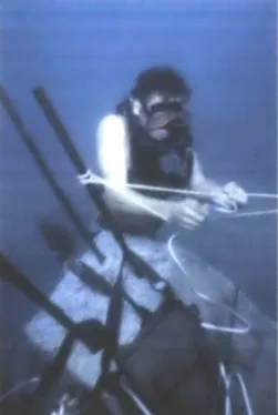
Figure 2.13 shows a segment of a network of explosive line that is routed throughout the beach area. A surf surge makes staying clear of hazards quite difficult.
Figure 2.13: Jap-Scully loaded with Explosives
The risk of human life does not exist only underwater. The threat from shore defenses can be extremely high. After the charges have been set, all the swimmers return to the pickup boat for extraction. Explosive charges are fired by timers or remotely, giving the men time to clear the area prior to the blast. Any swimmers not clearing the area can be incapacitated or killed by resulting underwater shock waves.
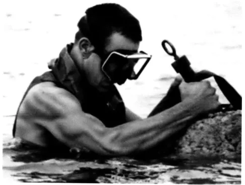
2.6 Ship Hull Inspection
Although the duties of the swimmers are primarily offensive against enemy obstructions along beaches, other tasks can be assigned. These can include making close-in shore inspections for enemy pillboxes and fortifications, charting underwater obstructions and mines and destroying them, marking or blasting channels, making maps of invasion landing routes, and other similar missions. Additional missions performed for friendly forces can include inspecting friendly ships for battle damage and propeller obstructions,
and other underwater work such as rescue and recovery. Figure 2.14 shows a swimmer under a ship, perhaps accomplishing a propeller inspection. Some swimmers can hold their breath up to three minutes without special breathing apparatus. This swimmer, with no oxygen -just mask and fins - may be able to conduct quite an extensive inspection
without going up for air. This research is ongoing for future AUV development beyond the research of this thesis.
Figure 2.14: Swimmer performing a ship hull inspection
2.7 History of A UV navigation and localization methods
Navigation
There are several navigation systems used by AUV researchers. One system is a non-acoustic approach; this system can be totally passive and requires no initial setup. The major method used in this approach is to install a GPS receiver and an inertial navigation system (INS). Throughout the mission, the AUV performs a number of surfacing
maneuvers to relocate itself and reset inertial navigation system (INS) drift. There are some downsides to this approach: if a hard requirement exists, such as no surfacing being allowed, the accuracy of the navigation system relies solely on the INS, which can become inaccurate after long periods, as navigational errors accumulate. An INS is also costly and difficult to implement. If this is the case, the high cost of an accurate INS can sway research to a different approach. Another approach is an acoustic method, where the range of a vehicle is determined from transponders using acoustics.
Acoustics
Acoustic systems require some additional setup and utilization of hardware components external to the vehicle in order to assist in navigation. Currently, the different approaches can be broken into four subsets: long baseline (LBL), moving long baseline (MLBL), short baseline (SBL), and ultra short baseline (USBL) [3].
In LBL navigation, fixed transponder buoys are pre-positioned to encompass an operating area. The working vehicle sends a transmission and waits for replies. By recording the two-way time of flight of the acoustic signal, the range can be determined, if a constant sound speed is known. This process is initiated by the AUV and returned by the transponder. Using multiple transponders, the location of the vehicle can be triangulated. Navigation using two transponders can be achieved, but the possibility of baseline ambiguity exists. Using three or more transponders eliminates this problem. The height or depth of the transponders must also be determined to minimize error. This method has been investigated by many researchers [4-7], [15], [16], [17].
Processes have also been developed to actively determine the location of the transponders to help minimize the error [4]. An LBL system is the primary navigation system of the Woods Hole Oceanographic Institute (WHOI) REMUS system [16], [17].
MLBL is similar to LBL by using a transponder and two-way time of flight measurements, but differs in that the transponders are on mobile surface platforms
allowing minimal setup and positioning of transponder buoys. In addition, the AUV area of operation is not confined by pre-located transducers. Tests performed by Curcio et al. in 2005 were able to track surface craft by using multiple platforms each carrying a single transducer to triangulate the location [7], [12].
SBL works by attaching multiple transducers to a single platform to track an AUV. The platform determines the location of the AUV by a modified two-way time of flights. A single transducer initiates a signal to the AUV. When the AUV responds, the one-way time of flight measurement is recorded by all receivers. Each of these measurements varies and needs to be normalized to a one-way time of flight by removing the initiation time of flight. The AUV location can be determined from as little as two transducers but as in the LBL case, ambiguity exists. The ambiguity can be eliminated by adding an additional transducer off the baseline of the first two transducers. The ambiguity can also be determined by angle changes of the baseline for sequential measurements or movement of the transducers. SBL has been employed on several different ROV and
AUV platforms [14].
USBL systems use a surface ship following at a close range. A one-way signal from the AUV is received by a number of receivers in close proximity on the surface ship. The
receiver system measures the difference in phase each receiver reports. This system does not allow for two-way communications. Bidirectional communication (sometimes through a tether) allows the AUV to receive updates of its position. In a reversed format, this system has also been used for terminal guidance into an underwater vehicle-capturing device [14], [15].
These navigation systems, LBL, and SBL, have been combined in the past in an effort to track sperm whales [15]. This method used SBL to estimate a relative direction to a sperm whale emitting clicks. On a submerged AUV tethered to a surface GPS buoy a four hydrophone SBL setup was utilized to determine the relative direction by calculating the difference in arrival times to the hydrophones. The single SBL system was employed on two vehicles. Two vehicles independently calculated bearing angle and elevation angles
to the target whale using the SBL systems. Using LBL techniques between the two vehicles allowed for an intersection and the probable location of the whale to be determined. The tests determine that a precise inclination measurement of the array was important to minimize error. It was difficult to quantify an absolute error because no ground-truth navigation system is available for whales. All error estimations were made
by observations of whale surface positions.
Localization
Acoustic range-only Self Localization and Mapping (SLAM) has been preformed by researchers using a variety of methods: Monte Carlo, Kalman filters, Markov Doppler/Compass/LBL assisted navigation filters have been tested, [4], [59], [60]. The Kalman filter assumes a multivariate Gaussian distribution [17], [20], which is fully described by a mean and a covariance matrix. Extended Kalman filters approximate linear solutions to nonlinear problems [21]. This allows for an efficient implementation, but divergence is also a potential problem with an extended Kalmen filter. The divergence is exacerbated when angle errors are high, and the Gaussian is a poor approximation.
Monte Carlo localization provides yet another method of representing multimodal distributions for position estimation. Also known as particle filtering, Monte Carlo localization approximates a distribution using a finite number of weighted samples. The estimated distribution is updated using importance sampling: new samples are drawn from the old distribution at random, propagated in accordance with robot odometry, and then weighted according to available sensor information. One advantage of Monte Carlo localization is that the computational requirements can be scaled as needed by adjusting the number of samples of the distribution [19], [59]. Computational complexity can be an issue with this approach.
For range-only navigation, research has shown Kalman filter tends to perform better then other approaches [59]. Tests were performed by Newman et al. [4] to determine beacon location and vehicle trajectory. Localization of the vehicle using multiple range
measurements along with vehicle depth created a two-dimensional problem to determine the vehicle location. A non-linear optimization algorithm was used to simultaneously determine beacon locations. Better results are achieved when multiple methods are used such as Kalman filtering with Doppler velocity log. Newman [4] performed test in 2002 to verify the capabilities of Kalman filters to locate accurately and AUV using range only measurements, Doppler and compass data. The results of this work showed that AUV tracking was possible.
In 2002, experiments were performed to enhance range-only location from two-way time of flight. An AUV was deployed using stationary acoustic transponder beacon as navigation aids. The locations of these beacons were known. A robust outlier rejection method was used to remove non-Gaussian noise [55].
Environmental Geo physical properties have also been used to determine underwater location. In 2003, Nygren and Jansson tested a technique using a bathymetric multibeam sonar to map the seabed topography. The data obtained from bathymetric image for a given area were compared to previously existing map. From this, the vehicle calculated its location within the previous map. The AUV was able to achieve accuracy from one to seven meters within a one square kilometer grid.
Geospatial navigation is not a promising method for clearing a beach. Historically, assault beaches have been chosen for a smooth gradient and sandy bottom. The ability to determine your location from bathymetric means requires a significant height change in the bottom images; sandy bottom beaches are typically smooth and gently sloped toward the shore. Sandy beach bottoms typically shift with the tide; forever changing small sand ridges on the seafloor lay down in different patterns with the prevailing current. The texture of these ridges is similar to an enlarged fingerprint with ridges in some cases reaching a maximum height of two inches. Navigation using these techniques is problematic because the a priori map will soon be obsolete due to changes in target locations and an altered bathymetry from tide and storms.
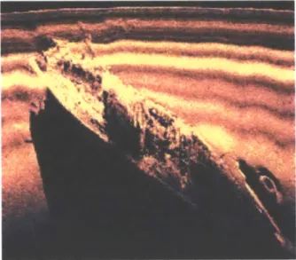
2.8 Sonar
There are two types of sonar used for creating the prior map for the final reacquisition of targets. The first used by the REMUS vehicle is a side looking sonar (SLS) [16]. It works by taking a thin picture of a small swath of the floor, and example is shown in Figure 2.15. The thin picture is perpendicular to the direction of travel. At the end of a run the thin pictures are stitched together to form a coherent image. This image will show
details of the ocean floor. It relies heavily on the shadows created by an object for recognition and classification. This is a labor-intensive process. Algorithms are currently being developed to minimize the human interface required.
Figure 2.15: SLS Image- USS Monitor of of
The capabilities of SLS mapping are extensive. They have been fitted to small AUV and performed well in a variety of roles. Most recently, a SAHRV (the military version of REMUS) was used to map Al-Basrah, an Iraqi oil port [16]. During this mission other assets were also employed. The SAHRV worked more effectively and cleared more area than any other platform. It was able to locate objects of interest for Navy divers to check.
The clarity of an SLS image is directly correlated to the stability of the vehicle carrying it. A smaller less stable vehicle is susceptible to uncontrolled motion, which skews the images. As the title suggests, SLS looks to the side of the vehicle. It has a fast update rate requiring minimum CPU speed to process the images because only a small swath is added after each return. It is not capable of seeing or recording features that are approaching the vehicle. This limitation eliminates it from being used as the sole device for location and terminal guidance of objects of interest in littoral waters.
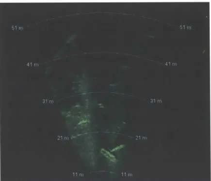
A Forward Look Sonar (FLS) enables the AUV to see what it is approaching. The image
return from a FLS is different than a SLS. The FLS image is similar to an overhead shot that depicts ranges and bearings. Each ping returns a new full image; a single ping return is shown in Figure 2.16. It does not perform as well in identifying objects, as shadows and the clarity are not as refined as the SLS.
Figure 2.16: FLS image- sunk sailboat in Charles river
The refresh rate is highly dependent on CPU speed because most systems require the image to be processed before the next ping is sent. The single image contains more information then a single swath of images from the SLS. Typically SLS refresh rates are
greater than those from a FLS. If processing of images can be controlled, minimizing
CPU overhead, the refresh rate can increase substantially. Technology is also processing
the majority of the image prior to reaching the main CPU. Taking this overhead off the main CPU will greatly increase the refresh rate.
Vehicles that contain both FLS and SLS have been developed and used with exceptional results. They allow the user to see an object of interest from both perspectives, furthering their ability to classify the object.
This chapter has shown the current capabilities of manned assets and techniques used for insertion and infiltration of a littoral beach. It has also described the current capabilities of the two types of sonar's available and provides an explanation of common navigation techniques in use today.
3. Advances in Design
This chapter presents the design of the RUSSO ASC, a robotic surface craft designed for autonomous deployment and operation of AUVs. The design has been developed as an extension of the Scout ASC, created by Curcio et al. at MIT [7], [12], [56]. We use the Nekton ranger as the target host AUV [6]. This chapter reviews the goals of the design and provides details of key subsystems, including vehicle modifications, hardware designs, and autonomous launch constraints.
3.1 Current design
The first version is the Scout ASC which provided an easy-adaptable test platform for developing algorithms and initial testing of new equipment for use on other platforms. Over the past few years, the Scout ASC has proven to be a sturdy and reliable platform that is used extensively for software and hardware validation. It has been used in support of multiple ONR field experiments, in a variety of environments, including ponds, lakes, and protected and unprotected ocean environments in both fresh and salt water. The Scout ASC has proven its ability to be rapidly configured by strapping on new sensors for evaluation and testing of software algorithms.
3.2
Wet bay construction
In order to build the next version of an ASC, a clear understanding of its purpose needed to be defined. This new ASC is to be capable of all of its past missions and be able to have an increase in durability of both hardware and software. The major design change for the new vehicle is the ability to house and launch an AUV from an internal wetbay, shown in Figure 3.1. The design is not limited to launching one particular vehicle. The wetbay is expanded to accommodate the largest possible payload allowable by the ASC hull, allowing for expansion of future roles and missions of the ASC.
Inner dimensions of the wetbay are fifty inches long, by ten inches wide and nine inches tall. The top is open to the middle section of the ASC, which allows for easy connection of hardware mounts and electrical connections. The bottom is also open to allow for the release of the payload at anytime and for payload sensors to be mounted below the hull. The open top, open bottom design adds flexibility in that the payload is not confined to fit
into the vertical area.
Figure 3.1: Wetbay frame and panels
Construction of the internal wetbay walls used quarter-inch thick High-Density Polyethylene (HDPE) welded at the seams. These seams serve as the first barrier in waterproofing the center section of the ASC. A second waterproof barrier is a coating covering all seams in the center section. The urethane epoxy sealant remains flexible once cured, thus allowing the wetbay to sustain some abuse while preserving its watertight integrity. The walls were supported by aluminum extrusions to disperse the torsional load on the walls. Aluminum "L" angle extrusion is used for the four vertical attachment, reducing the capability of the walls bulging between connection points due to water pressure and loads. A large (1%/") flange surrounds the base of the wetbay for two reasons. The first is to allow a gasket to be compressed between the flange and the ASC hull to form a watertight seal. The second is to add strength to the middle of the ASC.
We were concerned with the longitudinal and torsional strength of the ASC hull once the wetbay was installed because of the large amount of hull material removed from the center that was the original load dispersing webbing. In addition to the loss of strength,
fifty-eight percent of the ASC keel was lost from the open area consumed by the wetbay; the result would be a less-stable craft. To add dynamic stability, aluminum "T" angle extrusion was used on the left and right sides of the hull at the wetbay interaction, as shown in Figure 3.2, two bilge keels extend into the slipstream and allow for the attachment of additional keel components if necessary.
Figure 3.2: ASC front view with bilge keels
One by 1/8 inch bar was used to tie together the top four corners of the housing together, allowing for several attachment points to distribute the load evenly between the bay insert and the ASC frame rails.
Inside of the ASC, 8020 extruded aluminum frame rails were used to secure the wetbay, as shown in Figure 3.3. The ASC internal frame is further strengthened by the wetbay housing. The 8020 rails were bolted to the front and rear 3/4 inch thick HDPE bulkheads, forming a rigid box frame and adding strength to the hull.
Figure 3.3: Kayak with 8020 frame rails
The bulkheads were made slightly oversized for force fit in the front and rear then sealed into place. Over sizing the bulkheads does not allow for any movement of the frame rails in the ASC, as shown in Figure 3.4. Silicon glue sealed the three compartments to form three independent watertight chambers. This added safety in the design ensures that any one compartment can flood but the vehicle will remain buoyant.
The wetbay slips into the ASC framework from the bottom and is designed to be semi-permanent, as shown in Figure 3.5. However, the ability exists to replace the bay with only a minimum of labor.
Figure 3.5: Wetbay mounted in ASC frame
Once the AUV mounts are installed, the AUV can be mounted from either underneath or the top. Shown in Figure 3.6, a Nekton Ranger AUV is installed at a fifteen-degree downward angle, allowing the sonar head to be fully submerged for use during the transit. At this angle, the maximum range of the sonar in a typical water depth of 18 meters is 67 meters. The effects of this are discussed in detail in Chapter 4.
Figure 3.6: Ranger AUV mounted in wetbay
3.3 Cooperative Navigation Hardware
The surface navigation of an ASC is a simple process of GPS waypoint following, provided a high-level control has been implemented. A waypoint and thrust are defined and the ASC navigates a straight line to the waypoint then waits for the next instruction. During this process, it continuously updates its position using GPS and compass inputs. It