DEFORMATION AND RUPTURE OF
CYLINDRICAL SHELLS UNDER DYNAMIC
LOADING
by
Michelle S. Hoo Fatt
S.B. in Mechanical Engineering, Massachusetts Institute of
Technology (1987)
S.M. in Ocean Engineering, Massachusetts Institute of
Technology (1990)
Submitted to the Department of Ocean Engineering
in partial fulfillment of the requirements for the degree of
Doctor of Philosophy in the field of Structural Mechanics
at the
MASSACHUSETTS INSTITUTE OF TECHNOLOGY
June 1992
@
Massachusetts Institute of Technology 1992. All rights reserved.
Signature redacted
A uthor ... ... ...
Department of Ocean Engineering
Signature redacted
June 12 1992
Certified by...
Professor Tomasz Wierzbicki
Professor
The is Supervisor
Signature
redacted
A ccepted by ... . -...
A. Don
Carmichael
Chairman, Departmental Committee on Graduate StudentsARCHIVES
MASSACHUSETTS INSTITUTE
OF TFVHN01 O(y
'JUL 2 2 1992
DEFORMATION AND RUPTURE OF CYLINDRICAL
SHELLS UNDER DYNAMIC LOADING
by
Michelle S. Hoo Fatt
S.B. in Mechanical Engineering, Massachusetts Institute of
Technology (1987)
S.M. in Ocean Engineering, Massachusetts Institute of Technology
(1990)
Submitted to the Department of Ocean Engineering on June 12, 1992, in partial fulfillment of the
requirements for the degree of
Doctor of Philosophy in the field of Structural Mechanics
Abstract
The dynamic plastic response and failure of unstiffened and ring-stiffened cylindrical shells subjected to dynamic loads were studied. The proposed solution methodology, based on a simple computational model of the shell and the concept of equivalence parameters, incorporated two main load-resisting mechanisms in the shell: stretching in the longitudinal direction and bending in the circumferential direction. From this method, the complicated two-dimensional cylindrical shell problem was reduced to a one-dimensional problem of a string-on-foundation. In particular, the magnitude of the transient and final shape of the transverse deflections of the shell undergoing impact and explosive-type loading were predicted. In order to predict shell failure, the solution for the transient deflection was coupled with a simple fracture criterion - the critical strain to rupture. Both exact and approximate solutions for the impact and impulsive loading of the unstiffened shell were compared and gave similar results for high velocity impact and impulsive loading. In the ring-stiffened shell, the overall deflection profile was shown to consist of both a global and local (between stiffeners) deflection fields thereby revealing a complex interplay between the stiffener and the bay. Furthermore, a parametric study on the stiffened shell showed that string-on-foundation model for which ring-stiffeners are represented by lumped masses and springs is a promising method of analyzing the structure.
Thesis Supervisor: Professor Tomasz Wierzbicki Title: Professor
Dedication
Acknowledgement
There are many people who I need to acknowledge, but the most important one of them all is my advisor and mentor, Tom Wierzbicki. Despite the fact that most of our time was spent arguing, I was very fortunate to have met and worked with such a unique person. I have never learned (and probably will never learn) as much from anyone as I did from Tom Wierzbicki. To me, he remains one of the greatest teacher of all time!
Although I did not get to work closely with him until the very end, I would also like to acknowledge Professor Frank McClintock for pointing out inconsistencies where they appear and teaching me of even better ways of writing technical information. It is not often that one gets the attention of an engineering professor who is not only skilled in mechanics but also in the art of writing, and for this reason I am lucky.
I thank Mr. William McDonald and Dr. Minos Moussouros of the Naval Surface Warfare Center (White Oak) for providing both financial and educational support that was needed to keep this research ongoing. In particular, I dearly acknowledge Minos for supervising my work on both the dimple ring model and the contribution of the shear work rate. The research was supported by the Office of Naval Research under Contract No. NOOO 14-89-C-0301.
During my Ph.D. studies and the development of the thesis, I had the privilege of working with three other people, Professor R. Rosales (Applied Mathematics De-partment, MIT), Dr. Ion Suliciu, and Dr. Miheala Suliciu (both from the Institute of Mathematics of the Romanian Academy, Romania). Through our meetings and heated discussions, I was able to obtain some knowledge about non-linear wave me-chanics and its application to plasticity. The impact of these three people on my work will become more evident when reading the thesis.
I would also like to thank Professor Norman Jones (University of Liverpool), Professor Steve Reid (UMIST), and Dr. Bill Stronge (Cambridge University) who were kind enough to allow me to visit their respective universities. By learning of their work, I was able to return to MIT with the valuable information needed to solve
Finally, I would also like to acknowledge some very important people: Professor T. Francis Ogilvie, Row Selman, Muriel Bernier, and Judi Sheytanian. The final semester of Ph.D. studies was an unbearable time for me and without the critical advice from these people, I do not think I could of made it out in one piece. (Actually, I'm not sure I did.)
I1'
Contents
1 Introduction 15
2 Literature Review 18
3 Problem Formulation 22
3.1 Assumptions and Simplifications ... 26
3.2 Bending Work Rate . . . . 29
3.3 Membrane Work Rate . . . . 29
4 String-On-Foundation 30 4.1 The Concept of Equivalent Parameters . . . . 30
4.2 Equivalent Bending Resistance . . . . 32
4.2.1 Non-axisymmetric stationary hinge model . . . . 34
4.2.2 Ring resistance . . . . 36
4.3 Calculation of Other Equivalent Parameters . . . . 37
4.4 The Wave Equation . . . . 41
4.5 Dimensionless Parameters . . . . 44
5 Unloading Conditions 46 6 Projectile Impact into Cylinders 48 6.1 Summary of the Exact Solution . . . . 50
6.2 An Approximate Solution . . . . 54
6.2.2 Ballistic limits . . . . 60
6.2.3 Extension of the model . . . . 61
6.2.4 Damage of cylinders due to dropped objects . . . . 62
7 Explosive Loading on Unstiffened Shell 66 7.1 Impulsive Loading . . . . 66
7.2 Summary of the Exact Solution . . . . 69
7.3 An Approximate Solution . . . . 72
7.3.1 Modal analysis . . . . 72
7.4 Generalization for Different Pressure Distribution . . . . 77
8 Explosive Loading on Ring-stiffened Shell 78 8.1 An Exact Solution of the Partial Differential Equation . . . . 86
8.2 Unloading . . . . 93
8.3 Experimental Validation . . . . 94
8.3.1 Motion before unloading: Phase I . . . . 98
8.3.2 Motion after unloading: Phase II . . . . 99
8.3.3 Effect of stiffener footing . . . . 105
8.3.4 Neglect of bending work rate in the axial direction . . . . 105
8.4 Calculations of Strain Fields and Fracture Initiation . . . . 107
8.5 A Parametric Study . . . . 108
9 Conclusions 114 A Kinematics of the Stationary Hinge Model 116 B Evaluation of Oo, 01, and (2 119 B.1 Calculation of O0 . . . . 120
B.2 Calculation of 01 . . . . 121
B.3 Calculation of 92 . . . . . . . . 122
D A Special Orthogonality Condition 128
E Evaluation of Fourier Coefficients 130
F Lumped Mass M and Bending Resistance
Q
132F.1 Case A: hNA> h -- - -- - - - --... 133 F.2 Case B : hNA< h - - -- --- - --... 133
List of Figures
3-1 Geometry and loading of a cylindrical shell. . . . . 23
4-1 Possible cross-sectional shapes of the deformed shell. . . . . 33
4-2 Non-axisymmetric stationary hinge model. . . . . 35
4-3 Ring resistance. . . . . 38
4-4 Kinematics of the deformed ring. . . . . 40
4-5 Variation of 01 and 02 with w,/R. . . . . 42
6-1 Impact of a spherical projectile on an infinite tube and a simple com-putational model. . . . .. 49
6-2 Phase plane analysis of impact into cylinder. . . . . 52
6-3 Permanent longitudinal deflection profiles of a cylinder for various val-ues of the mass ratio parameter. . . . . 55
6-4 Growth of the dimensionless shell deflection with time at the point of im pact . . . . 56
6-5 Instantaneous velocity profiles of the shell. . . . . 57
6-6 Damage of a tubular member caused by a dropped drill-collar as a function of the drop height. . . . . 64
7-1 Unstiffened shell modeled as a rigid-plastic string on a rigid-plastic foundation. . . . . 67
7-2 Propagation of unloading waves (-boundaries) in a pressure loaded shell for various values of the dimensionless impulse. . . . . 70
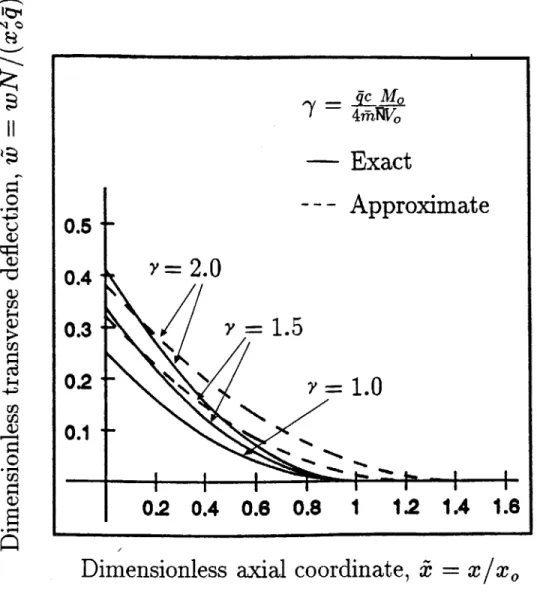
7-3 Normalized permanent deflection profiles of an unstiffened shell for
small (f = 0.1) and large (I = 0.89) dimensionless impulse. . . . . 71
7-4 Dimensionless central deflection versus time (comparison of the exact and approximate solution). . . . . 75
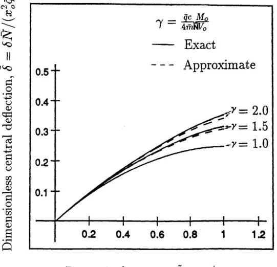
7-5 Dependence of dimensionless permanent central deflection on the mag-nitude of im pulse. . . . . 76
8-1 Ring-stiffened shell subjected pressure loading. . . . . 80
8-2 Global and local deformations of a ring-stiffened shell subjected an impulsive loading. . . . . 82
8-3 A continuous-discrete model of a single bay in the ring-stiffened shell. 85 8-4 Shifting of the neutral axis. . . . . 87
8-5 Geometry of a ring-stiffener and the concept of an effective breadth of the stiffener footing. . . . . 88
8-6 Stepwise initial velocities of the stiffener and the shell produced by a uniform impulse. . . . . 89
8-7 Experimental profiles . . . . 95
8-8 Stiffener dimensions. . . . . 96
8-9 Normalized transient deflection profiles within the central bay. .... .100
8-10 Normalized transient velocity profiles within the central bay. . . . . . 101
8-11 Transient deflection profiles for the central bay (using modal analysis). 104 8-12 Final deflection profiles for varying stiffener footing. . . . . 106
8-13 Maximum deflection v. impulse parameter. . . . . 110
8-14 Maximum deflection v. mass parameter. . . . . 111
8-15 Maximum deflection v. stiffness parameter. . . . . 113
List of Tables
4.1 Equivalent parameters calculated for the stationary hinge model . . . 43 6.1 Comparison between the experimental and theoretical ballistic limit in
the tests reported by Stronge. . . . . 62
6.2 Geometrical and mechanical parameters of a typical offshore tubular member hit by a drill-collar. . . . . 65
8.1 8.2 8.3
Pressure loadings . . . ... ....
Calculated quantities for the shell .. . . . . First ten eigenvalues calculated for the mass ratio 7 = 1.45. . . . .
98 99
NOMENCLATURE
C - 0ao/p transverse wave speed
f=
T/(qle) normalized shear forceh plate thickness
hb equivalent bending plate thickness
hi equivalent inertia plate thickness
hNA neutral axis
21 length between bays
li,12 lengths to divide bay and stiffener 1, characteristic length for normalization l, length between stationary hinges
m = ph mass per unit area of cylinder
in equivalent mass per unit length n integers
p pressure load p equivalent line load p, pressure load amplitude
q bending resistance per unit length
r radial component
r, radius of projectile
t time
tf response time
u axial deformation
ui components of displacements vector
v tangential displacement w transverse or radial deflection
wf final transverse deflection
x axial coordinate
X0 = N /q characteristic length
W
work rateP
axial forceF., G., H coefficients of eigenvalue expansion terms
I
impulseIc critical impulse to rupture
2L extent of pressure load
Rt stiffener mass
Mb total bending moment
M, characteristic mass M, impacting mass
M,1 fully plastic bending moment
Ma, bending moment tensor
N
equivalent tensile forceN,1 fully plastic membrane force Na, membrane force tensor
Q stiffener bending resistance
R shell radius T shear force Ti surface traction V impulse velocity Vc characteristic velocity V, impact velocity
a0 fixed hinge angle
#3
hinge angle= (cqMo)/(477N]V0) critical parameter for impact
Sf final central deflection
8g global central deflection
S local central deflection
e strain
Ec critical rupture strain
'Ema maximum strain
9 circumferential coordinate
= Q/(qle) stiffness ratio
= Mc/(;inlc) mass ratio
o
integrals in the circumferential coordinate K curvature.A eigenvalues
i / = 1/12 length ratio
V = Va/c velocity ratio
2 length of deformed zone
2 f final length of deformed zone p material density a stress C-. flow stress r decay constant
4
hinge angle 1 jump in rotation()
or () time derivative0'
or(),
derivative with respect to x()
normalized quantityChapter 1
Introduction
Accurate predictions of the dynamic plastic deformation and rupture of unstiffened and stiffened cylindrical shells subjected to high intensity transient loading are of great importance in many industrial applications. In the offshore industry, for in-stance, tubular members such as the corner legs or bracing element of drilling plat-forms may undergo local damage due to collisions with supply vessels or dropped object impact. Nuclear and chemical industries are interested in the safety of piping systems and pressure/containment vessels subjected to accidental pressure burst, pipe whipping, or missile impact. Research in submarine survivability against underwater explosion is actively pursued by the defense industry. Finally, the aerospace industry is interested in limiting or containing damage that may occur to transport aircraft fuselages, rockets or space stations caused by different types of accidental loads.
Early research on dynamic buckling and failure of cylinders was restricted to axi-symmetric external radial pulse loading
[1].
The corresponding analysis, however, is of limited applicability because axi-symmetric dynamic loading seldom occurs in practice. In real world situations loading is usually applied to one side of the cylinder and is characterized by various degrees of locality. It may consist of a projectile, missile or mass impact, stand-off explosion described by a pressure pulse or contact explosion which can be often approximated as an ideal impulsive loading.Depending on the load intensity and the spatial distribution of contact pressures, various forms of damage may result ranging from large amplitude lateral deflections to
punch-through penetration, fracture initiation at the base plate or the so-called stiff interfaces (clamped boundaries/base of stiffeners) [2], progression of tearing fracture, and finally massive structural damage. Damage to stiffeners themselves may include tripping failure (lateral plastic instability) [3] and detachment from the base plate. With still increasing load intensity, fragmentation of the shell will occur [4]. Due to the complexities introduced by unsymmetric loading and the large displacements and rotations of the shell amplified by material nonlinearities, the problem does not easily lend itself to an analytical treatment. However, by introducing a suitable set of assumptions a simple and realistic shell model can be developed that captures two dominant deformation mechanisms in locally loaded shells: axial stretching and circumferential bending of a shell element. The model can be interpreted as a rigid-plastic string resting on rigid-rigid-plastic foundation in which the two mechanisms are present in the form of plastic axial resistance of the string and foundation resistance, respectively. This model will be shown to be very effective and powerful in solving a class of engineering problems involving impact and explosive loading. Over the past few years a great deal of credibility has been added to the model by showing that theoretically predicted deflection profiles and amount of structural damage agrees with experimental data [5, 6, 7].
Finding a closed-form analytical solution for the shell under large deflection non-symmetric loading is mathematically complex. Moreover, the case of pressure loading on a ring-stiffened shell is further complicated by ring-stiffeners, which may undergo tripping and fracture during the explosion. Because of the difficulties in finding closed-form solutions to a set of coupled shell differential equations, past researchers have resorted to using empirical methods [8] or by using computer codes [9]. Solutions for the elastic response of the unstiffened shell due to pressure loads have been found
[10, 11, 12, 13, 14, 15], but very little has been done in addressing the plastic response
of the shell [16, 17]. Moreover, Huang [18] and Geers [19, 20] have furnished analytical solutions to the linear elastic fluid-solid response of a submerged, infinite, circular cylindrical shell excited by transient acoustic waves. Geers and Yen [21] attempted to find the underwater inelastic response of a cylindrical shell by setting it up as a
fluid-solid interaction and using the finite element method (FEM) to model the structural behavior and the boundary element method (BEM) to model the surrounding fluid.
This thesis is concerned with the dynamic plastic response and failure of a cylindri-cal shell subjected to several types of locylindri-calized dynamic loading. Based on justifiable assumptions on the rate of internal energy dissipation of the shell, an analytical solu-tion for the shell deformasolu-tion is found by developing a simple computasolu-tional model. In particular, three specific problems will be analyzed in detail: (i) mass impact on metal tubes; (ii) pressure pulse loading of a stiffened cylinder; (iii) impulsive loading of a ring-stiffened shell. Parametric studies are performed on each solution and where possible, theoretical predictions are compared to experimental data.
Chapter 2
Literature Review
Literature on the transient response of cylinders to impact and impulsive loading is limited but has been rapidly growing over the past five years. Gefken [22] extended the earlier analysis by Lindberg and Florence [1] to one-sided inward radial pressure that varied as the cosine of the angular position around the shell and was uniform along the length. Experiments performed on short, fully clamped shells revealed that the response modes consisted of dynamic wrinkling in the hoop direction followed by large inward deflections of the shell. This type of behavior is characteristic for shells that are quite thin (radius to thickness ratio, R/h = 240).
Thicker shells or thin shells reinforced by ring stiffeners develop a single dent with-out any wrinkling. For example, local dimple deformation of thicker tubes (R/h < 40) subjected to missile impact were described by Stronge [23] and Corbett et al [24] and compared to static deflection under punch loading. Localization of plastic deforma-tion was observed with increasing impact velocity.
Over the last few years general purpose nonlinear finite element codes were used to model and solve a class of dynamic shell problems. A successful application of
DYNA-3D computer code was reported by Kirkpatrick and Holmes [25] and Prantil
et al [26]. Work at the Stanford Research Institute over the last five years has recently been summarized by Holmes and Kirkpatrick [27]. Trinh and Gruda [28] presented a solution of a projectile impact problem on a cylindrical shell. The incorporation of a continuous damage model to DYNA-3D code opened a possibility of predicting
failure initiation and progression of fracture in thin cylinders and other structures
[29].
Parallel to numerical studies, an entirely new and promising line of research has emerged based on the modeling of a cylindrical shell as a plastic string resting on plas-tic foundation. The analogy between a cylindrical shell under axisymmetric loading and a beam-on-foundation originated in elastic shell theory [30]. In 1977, the model was re-discovered by Calladine [31] in order to address problems of non-axisymmetric loading of elastic spherical and cylindrical shells. Then shortly after this, Reid [32] ex-tended the beam-on-foundation model into the plastic range by studying the pinching of rigid-plastic tubes. Even more recently, Yu and Stronge [33, 34] used the beam-on-foundation model to calculate the deformation of a cylindrical shell undergoing projectile impact. To accommodate that class of problems for which the central de-flection of the shell is of the order several times the shell thickness, it is proposed to extend the beam-on-foundation model even further into the plastic range so that the
analogy is now made between a cylindrical shell and a string-on-foundation. Gurkok
and Hopkins [35] have shown that finite deformations cause significant geometrical changes in a fixed rigid-plastic beam under transverse loads. When the central deflec-tion of the beam is of the order of its thickness, membrane forces predominate thereby enhancing the beams load carrying capacity and rendering the beam to behave like a string (membrane state). The rigid-plastic cylindrical shell undergoing moderately large deflection would therefore behave more like a string-on-foundation rather than a beam-on-foundation.
The dynamic response of the plastic string (without foundation) was extensively studied during and after World War II [36, 37]. However, apart from the problem of the aircraft impact on a balloon barrage cable, no other practical applications of these solutions were found. The addition of a plastic foundation constant to the string has put the model in an entirely new perspective. While the string represents the average weighted axial strength of a shell, the foundation describes the shell resistance to lateral crushing. With the two major force-resisting mechanisms of the cylinder included in the formulation, the string-on-foundation appears to be a realistic (when
compared to experimental results) shell model for a variety of dynamic problems. Mathematically the string-on-foundation problem is described by an inhomoge-neous wave equation which due to the rigid-plastic assumption is subjected to non-linear loading/unloading condition. Many interesting features of the initial value problems for this equation are revealed in recent publications. An exact solution to the inhomogeneous wave equation under mass impact boundary condition, recently derived by Rosales et al [38] using the method of characteristics, serves as a bench-mark solution to various approximate solutions and also helps determine the range of validity of these approximations. In a study of projectile impact on a cylindri-cal shell, Wierzbicki and Hoo Fatt [39] used the exact results of the velocity field, a new concept of a propagating extensional hinge and the principle of conservation of linear momentum to predict the ballistic limit of the shell. The general method-ology was subsequently used to predict the permanent damage that results from a drill-collar accidently falling on one of the tubular members of an offshore platform [40]. In the higher velocity range the theoretical maximum deflections calculated by Wierzbicki and Hoo Fatt [39] were shown to agree with experimental profiles measured
by Stronge [23]. The theory has also been successfully used in finding the ballistic
limit and post-perforation velocity for projectile impact into circular plates [7, 41]. Theoretical predictions of the ballistic limit were found to be within 10 percent of experimental results for thin aluminum and steel plates.
The string-on-foundation model has also been also used to analyze local plas-tic damage up to fracture of cylinders subjected to explosive loading. Suliciu et al [42] derived a closed form solution for the large amplitude transient shell response subjected to an exponentially decaying pressure pulse and an ideal impulse loading distributed as a cosine square function along the axis of the cylinder. Static strength and deformations of ring stiffened shells were studied by Onoufriou and Harding [43], Onoufriou et al [44], Ronalds and Dowling [45] and Hoo Fatt and Wierzbicki [6]. Finally, Hoo Fatt and Wierzbicki formulated and solved approximately the problem of impulsively loaded ring-stiffened shell [46]. The deflection profiles calculated from these solutions were shown to correlate well with limited experimental data, taken
from Reference [47].
In many practical applications, the pressure pulse loading results from an under-water explosion. The problem of fluid-solid interaction has received a great deal of
attention in the literature. Most of the results were restricted to elastic response of shells, [18, 19]. More recently Geers and Yen [21] extended the analysis to the in-elastic deformations. However, the range of deflections considered by Geers and Yen was by far smaller than the deflection permitted by the beam-on-foundation model. Clearly, more research is needed to close the gap between the technologies developed using large deflection theory without the fluid-solid interaction and that considering the fluid-solid interaction but restricted to small deflections. The analytical solution presented here may be considered as one attempt to form this bridge.
I
Chapter 3
Problem Formulation
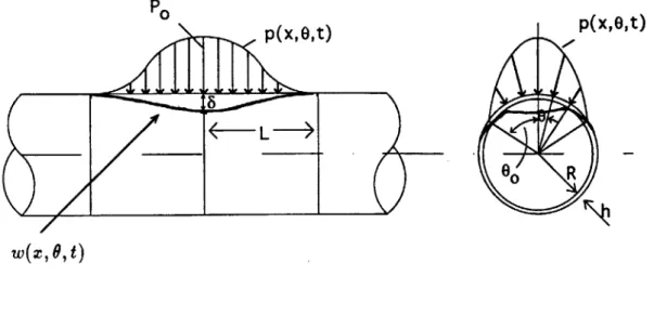
The formulation is kept general so that the proposed methodology may be applied to both the unstiffened and ring-stiffened cylindrical shell subjected to high inten-sity, localized, dynamic loads - impact, pressure pulse, impulsive. Consider a long cylindrical shell of thickness h, radius R, and mass density p as shown in Figure 3-1. If the shell is ring-stiffened, the shell thickness would be a varying function of axial displacement x. Chapter 8 deals with such a shell. However, for simplicity we will represent the general shell as an unstiffened one and show how ring stiffeners are incorporated into the model in Chapter 8. The shell material is idealized as rigid, perfectly-plastic with flow stress 0-. The cylinder is subjected to an applied pressure load p(x, 6, t) and undergoes radial deformation w(x, 6, t), where x, 6 denotes the axial
and circumferential coordinates and t denotes time. Later it will be seen that the maximum radial deflection becomes transverse deflection of the shell. The maximum amplitude of the transverse deflection is denoted by 8.
For the reader's convenience, the following sections define certain basic quantities and concepts:
Material In the range of moderately large deflection, elastic deformations are neg-ligible compared with plastic deformations. Therefore, the material is assumed to be rigid-perfectly plastic, described by a flow stress a,. For an actual work-hardening material, the flow stress is understood as a constant, elevated stress corresponding to
P0
p(x,0,t)
p(x,0o R
Ot)
W(X, 0,t)
Figure 3-1: Geometry and loading of a cylindrical shell.
A
an average strain e., in the loading process, o1, = g(Eav).
The determination of 0, requires an iterative procedure in which the problem is first solved to find an average strain, then the magnitude of the flow stress is suitably
adjusted to match this average strain.
Loading In general the shell is loaded by an inward radial pressure p(x, 9, t). The size of the "patch" load is of an order of the shell radius or smaller so that the resulting deformations are highly localized. As shown in Fig. 3-1, the pressure distribution is assumed to have two planes of symmetry, at x = 0 and at 9 = 0, and a variable amplitude but a fixed shape. The pressure amplitude rises instantaneously to the maximum value p, and then decays exponentially with a characteristic time constant
r, according to
p(x, 0, t) = p.e- f(x)g(6), (3.1)
where f(x) and g(O) are known, dimensionless shape functions. In the case of impul-sive loading, the pressure is taken to be zero and the loading is introduced to the shell through the initial condition for the shell velocity. In impact situations the loading is introduced through both the boundary condition (at the point of impact) and the initial condition (initial velocity at the point of impact). Illustrative examples of each type of loading mentioned above will be given in the subsequent chapters.
Stresses and Strains Corresponding simplifying assumptions on the stresses will be discussed dealing with the rate of internal energy dissipation in the shell.
Assuming plane stress and the Love-Kirchhoff hypothesis,
iaa = i'ao(x,
9)
+ Z ak0(X,9),
[a,f]
= [X, ], (3.2)Equilibrium The overall shell equilibrium is expressed via the principle of virtual velocities
knt, (3.3)
where We.,t is the rate of external work and Win is the rate of internal dissipation of energy. Equation (3.3) can be expressed in shell coordinates for which dSO = dxRdO:
FUIenda + TWIenda + TinidSo + j (-mii)itidSo =h j ij iijdSo, (3.4)
fso foSO
where the velocity vector are ii[iL, i, zb] corresponding to the x, 6, r axis, the dot
de-notes time derivative, m = ph is the mass per unit area, aij and i;j denote components of stress and strain rate vector, and Ti a vector of surface tractions with components
Ti[0, 0, p] in the x, 0, r direction. In addition there may be an axial load P(t) applied
along the axis of the tube and a concentrated shear load T(t) at the ends (the bars on these quantities will later denote quantities that are integrated in the circumferential direction). Notice also that rigid body velocities, it and ib, are assumed beyond the plastically deformed region of the shell. Hence the first two terms of Eq. (3.4) are not integrated over the surface area. The radial deflection w can also be interpreted as deflection in the transverse direction (see Fig. 3-1).
It is assumed that u = 0. The justification of this approximate assumption follows from the symmetry of the problem it(x = 0) = 0 and that outside the local deforming
region the axial displacement of the shell is zero. Therefore it is small in the deforming
region and can be neglected compared to the remaining components i; and tb.
Using the Love-Kirchhoff assumption, Eq. (3.4) reduces to
TwIend.
+ f ptbdSo + f -m(ibi + ib)dSo =(Naoao + Mcqik;ce)dSo, (3.5)
where i,, and *a are the generalized strain and curvature rate tensors, and NO
-1
Here, a Lagrangian formulation is used so that the components of the strains and curvature rate vectors should be calculated in the material description.
For moderately large deflections, certain simplifying assumptions can be made to reduce the internal forces to only the membrane stretching and circumferential bending. These assumptions will be fully explained in the following section.
3.1
Assumptions and Simplifications
Most of our assumptions and simplifications will be concerned with the generalized forces and displacements of the shell and will be valid only for relatively thin shells, 20 < R/h < 150. The rate of internal work dissipation in the shell is given explicitly
by
Wt = 2 2R
j
M(X ke. + Me kee + 2MxeekTe + Nexi.. + Nee ee + 2Nxae)dOdx.0 0
(3.6)
However, for shells undergoing moderately large deflection, 6/R
<
0.2, some of these energy components are negligible. The following simplifications are made in a step-by-step fashion:1. Experiments show that the shell is can be assumed to be inextensible in the
circumferential direction, ee = 0. (For very thin shells, R/h > 100, this would
not be the case.) Hence the rate of energy associated with hoop compression or tension is zero.
2. The rate of bending work rate in the axial direction is neglected, M,,k,, = 0.
During early shell deformation, the curvature rate in the axial direction is small,
k ~ 0 (this assumption will be re-examined in Chapter 8). When the shell deflections are several time the magnitude of shell thickness, *.. increases but the axial bending forces Mr, becomes negligible (membrane state). The net result is that M.*e = 0 throughout deformation of the shell.
I
3. A previous analysis of a tube under knife loading [48] shows that the shear work
rate components, 2M.eke and 2N.9i.0, are insignificant in the early stages of deformation, S/R < 0.2. This theory is further substantiated by previous work done on the crushing of tubes by Wierzbicki and Suh [5] in which the neglect of the shear energy terms led to the over-prediction of the force-deflection relation
by some 10-15 percent when compared to experimental data.
So far with respect to these three assumptions, the rate of internal energy dissipation reduces to
Wnt = 2 2R
j
(M,,k,, + +N.,0,i,)d~dx. (3.7)0 0
4. The next assumption pertains to material behavior. A rigid-perfectly plastic, isotropic, and time independent material is assumed. Hence strain-hardening, strain-rate effects, and elastic vibrations are neglected. These effects tend to reduce deflections. The rigid-plastic assumption is further substantiated by the fact that calculations for this class of problem show that the strains are two orders of magnitude greater than the maximum elastic strains that metal shells can tolerate. Any elastic strains are negligible during deformation.
An average flow stress o,, which lies somewhere between the yield and ultimate strength can be used to approximate a strain hardening material. As stated ear-lier, an iterative scheme by which the flow strength is calculated based on equal area under the stress-strain curve may be used for a more accurate analysis.
5. As in practical applications of limit analysis, a simplified interaction surface is
assumed. In a more exact analysis N., and Me# are coupled through a yield condition,
f(Mc, Nao) = 0 (3.8)
Of
Of
(39)
where
A
is a proportionality constant. Then together with Eq. (3.9), the first two assumptions, iee = 0 and ki, = 0, can be used to express the yield conditionin only four independent quantities. Using a yield condition, such as the Huber-Mises yield criterion, the interaction curve would be seen as nonlinear elliptic yield surface in four-dimensional surface. Instead of this complicated interaction surface, a square-type yield locus is assumed such that
|M601 = MP1,
INzwI
= NI, (3.10)where Mpj = o-oh2
/4
is the fully plastic bending moment per unit length andNp, = ooh is the fully plastic axial force per unit length. Thus the stress
distri-butions at each cross-section normal to the principal direction are independent of each other.
Using this final simplification Eq. (3.7) reduces to
Wit = 2 j2R ( Mpikee +
IN,;i.,)dedx.
(3.11)0 0
The absolute sign is added to ensure that the rate of energy dissipation is always positive, regardless of the sign of kee or i..
The two terms on the right hand side of Eq. (3.11) represent the rate of bending energy in the circumferential direction (crushing of rings) and the rate of axial mem-brane energy (stretching of generators), respectively. In a previous analysis [49], a simplified shell model was built based these two components. The model consists of a series of unconnected rings and a bundle of unconnected generators. The rings and generators are loosely connected, but deformations are compatible.
3.2
Bending Work Rate
Under large plastic deformation of the rings, hinges develop in areas of localized plastic flow. The first term in Eq. (3.11) contains the rate of bending work in both continuous and discontinuous velocity fields. With the inclusion of plastic hinges, the rate of bending work per unit length Wb can be explicitly written as
Wb = 2Rj IMii'(eeldedx + 2 M )[](), (3.12)
where [Q](') denotes a jump in the relative rotation rate across a stationary or moving
hinge line. Note that the slopes must be continuous at the moving hinge in Eq.
(3.12). The conditions for the kinematic continuity at a moving hinge can be found
in Reference [50]. Furthermore, only the last term of Eq. (3.12) is used in the development of stationary hinge models.
3.3
Membrane Work Rate
Following moderately large deflection theory, a Lagrangian description of the axial strain rate is given by
i_= it' + w'zb', (3.13)
where u is the deformation in the axial direction and the primes denote differentiation with respect to x. However, the cylinder is modeled under fixed end conditions and axial deformations may be neglected: u = 0. Substituting this into the expression for
membrane work rate Wm, one gets
Wm = 2 j 2R |Npiw'>'|d~dx. (3.14)
The following section shows that with the use of equivalent parameters both the bending and membrane work terms can be reduced to a single integral in x.
1.
Chapter 4
String- On-Foundation
The analogy of a cylindrical shell undergoing large plastic deformation and a string-on-foundation will be made here. First, however, the results from the previous chapter is substituted into the statement of global equilibrium
TIlendsa + 2 2R p(x,0,t)tb(x,0,t )ddx = 2 2Rj IMPIkeeldedx +
2 j 2R j Npiw'tb'(x, 0, t)dedx + 2 j 2R j m(&& + i&b)(x, 0, t)d0dx (4.1)
0 0
where L is the extent of the load on both sides of the symmetry plane. Notice that the thickness h in the ring-stiffened shell will vary in a piece-wise manner along the x-axis so that both M,1 and m are in general functions of position x.
4.1
The Concept of Equivalent Parameters
As in previous work [51], integration in the circumferential direction can be performed, provided that the velocity field in the circumferential direction is known. Development of the stationary hinge model not only gives a realistic deformation pattern for the collapse of each ring but it can be used to derive certain kinematic quantities that lend themselves to certain functions which will later on be defined as equivalent parameters. It will be shown that these functions are roughly constant in magnitude.
1I
For this reason they are called equivalent parameters.
Equation (4.1) can be integrated in the 6-direction to give the following:
TW|enda + 2 p(x, t)zb(x, t)dx = 21 qtb(x, )dx +
2 j Nw'ib'(x, t)dx + 2 fiunttb (x, t)dx, (4.2)
0 fo
where the following equivalent functions are introduced: an equivalent line load,
p(x, t)tb(x, 0, t) = 2R j p(x, 6, t)tb(x, 6, t)d6; (4.3)
an equivalent bending resistance,
-q(x,t)tb(x,0,t) = 2Rj IMPikeejdO; (4.4)
an equivalent tensile force,
Nu'(x,0, t)w'(x, 0, t) = 2RN, jw'ib'(x, 6, t)d6; (4.5)
an equivalent mass per unit length,
WiT7(x, 0, t)zb(x, 0, t) = 2Rm j (Ibtb + si)(x, 6, t)d6. (4.6)
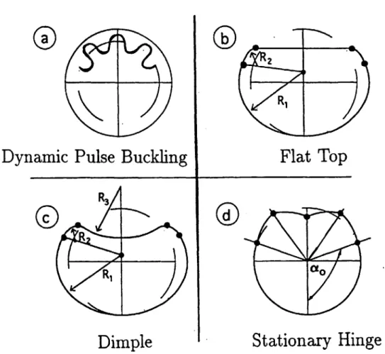
Notice that all the deformation in the circumferential direction is lumped into the deflection at 6 = 0 so that from here on, w will be only a function of x, t. As hinted earlier, a bar is used to denote a quantity that has been integrated in the circumferential direction. Calculation of these equivalent functions requires some assumptions on the deformation shape of the rings. Several possible deformation profiles in the cross-section of cylinders are shown in Fig. 4-1. Cylinders and rings subjected to a uniform symmetric inward radial pressure deform as shown in Fig. 4-la. The process known as dynamic pulse buckling involves circumferential bending
superposed on hoop compression [1]. The remaining three deformation modes are inextensible in the hoop direction. The kinematic model shown in Fig. 4-1b was developed by Wierzbicki and Suh [5] for static tube indentation under a "knife"-type punch. It consists of a flat top section and two circular arcs. This model was extended by Moussouros and Hoo Fatt [52] for impact or local pressure loading
by replacing the flat top portion with a circular are thereby creating a "dimple"
model, Fig. 4-1c. The kinematics used to describe the deformation of the dimple model became very complicated because several independent variables were needed to describe its deformation. A good approximation to the more realistic dimple model is an unsymmetric stationary hinge model, 4-1d. The stationary hinge model consists of five stationary plastic hinges with rigidly rotating and translating ring segments. Notice that the kinematic model shown in Fig. 4-1d is easier to deal with because it is essentially one-degree-of-freedom models. This means that central deflection wo or
w(O = 0) uniquely determines the kinematics of the problem provided the position of
outside hinges.
The derivation of the bending resistance q is treated as a separate problem by first examining the crushing force of a ring (per unit width).
4.2
Equivalent Bending Resistance
Experimental observations [47] show that the cross-sectional shape of the cylinder is a dimpled profile as shown in Fig. 4-1c. A separate analysis using the upper bound limit analysis technique to find the crushing force was done using this profile [52]. However, the dimple model, though realistic, required several independent variables to completely describe its deformation and thus led to a very complicated minimization procedure. Minimization had to be done numerically. Recently, it was found that a stationary hinge model, for which the location of hinges is defined by the angle a, shown Fig. 4-1d, can be described by only one independent variable, the maximum or central (9 = 0) displacement of the ring, and gives similar results to the dimple
model. Because of this one-parameter representation of the crushing force and ring
Dynamic
0R
Pulse Buckling
Dimple
2 R,Flat Top
0
aoStationary Hinge
kinematics, the stationary hinge model is favored and will be adopted in this analysis.
4.2.1
Non-axisymmetric stationary hinge model
The stationary hinge model described in Fig. 4-2 is non-symmetric and differs from the earlier one proposed by De Runtz and Hodge [53], which considers the symmetric crushing of tubes. The stationary hinge model is described by five hinges, A, B, C, D, and E, as shown in Fig. 4-2. The angle which describes the location of the fixed hinges, C and E, is given by a,. The remaining hinges, A, B and D, are such that they bisect the upper portions of the ring. Therefore, ~iU = ~f~1 = B= B7fC = 10.
During deformation B and D rotate while A translates downward by a distance
w,, where w, = w(O = 0) is the central deflection of the isolated ring (see Fig. 4-2).
Thus motion is simply described by the collapse of rigid bars EP7, ~A, TlB, and
fBlC.
Notice that any point in the ring that lies within LEOC does not deform.The deformation w(9) (see Fig. 4-4) can be described by a single time-like param-eter we,, given a fixed angle a,. However, to simplify the derivation of the deflection profile around the ring, two intermediate angles will be defined in Fig. 4-2, q and 3. The initial values for these angles (corresponding to w,, = 0) are denoted 0, and 3,
(see Fig. 4-2).
Initially, LAOB = LBOC = (ir - ao)/2 and both AOB and BOC form isosceles triangles such that LOBA = LOCB = 7r/4 + a,,/4. The initial values of 0,, and P, are therefore,
00 = 3a,,/4 - 7r/4 and 3, = r/4 - a,/4. (4.7)
During deformation, w, is related to q and
3.
In the vertical direction,w, = AA' = AO - A'O. (4.8)
Hence
A to (t 0 E go C E ! C A D 0 w 0 Bt B ao C Undeformed Deformed
Figure 4-2: Non-axisymmetric stationary hinge model. PO PO I > B O I I I
where 1, = 2Rcos(a. + q4).
Furthermore, taking components of
2ID-
and BC' in the horizontal direction,f
and 0 are related to each other by
locos/ = lsinb + Rsina,. (4.10) Note that again 0,, and 0,, can be determined for a given a, from Eqs. (4.9) and (4.10) by setting w, = 0.
4.2.2
Ring resistance
The resistance due to bending of a force q is simply found by again using the principle of virtual work
4A0 = 2[12Mplok + I2Mpid3]. (4.11)
This equation can be further rewritten in terms of 0 by taking the time derivatives of Eqs. (4.9) and (4.10). From Eq. (4.10),
#OSO =(4.12)
sinfl
and also from Eq. (4.9),
= 10 Cos( . (4.13)
sin#
Substituting Eqs. (4.12) and (4.13) into Eq. (4.11) and canceling
4
on both sides of the equation, gives the normalized crushing force of the ring as2sin3[1 + - .51j] MP, cos(a, + O,)cos( - ,)(
The absolute sign in Eq. (4.14) ensures that the rate of energy dissipation is always positive. For pressure loading, the value of a, may be adjusted to match experimental profiles.
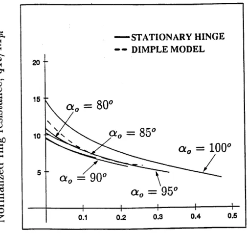
The normalized crushing force qR/M,1 for several values of a, (solid line) is
com-pared to that of the dimple model (dashed line) in Figure 4-3. Due to geometrical constraints, the stationary hinge model undergoes locking (no additional deflection can occur) for the smaller values of a, (for instance, see a. = 800 and ao = 85* ). In fact, to achieve deflections of the order w,,/R = 0.2, ao should be greater than ix/2. In a more realistic ring deformation mechanism, the angle a, should increase as the ring deforms. One may argue, however, that in such a case the ring model would no longer be a stationary one. For simplicity, a0 will be kept a constant value, a = Ir/2.
Incidently, a0 = 7r/2 gives the lowest crushing force curve.
As in the dimple ring model, the bending resistance varies weakly with central deflection, and will be taken as a constant value given by
8M,1
q = . (4.15)
R
This crushing force is equal to the one used by Wierzbicki and Suh [5] in which a different non-symmetric ring model was used. The fact that these two forces are similar is an indication of the insensitivity to the assumed mode of deformation for non-symmetric ring models.
4.3
Calculation of Other Equivalent Parameters
In evaluating the other equivalent parameters, the deformation of each material point on the ring must be calculated. A Lagrangian description of the problem is used to describe deformation shown in Fig. 4-4. For a given deflection w,, the deformation of each material point of the ring must be described in two regions 0 < 0 < (7r - ao)/2 and (r - a,)/2 < 0 < 7r - ao. In region (7r - a)/2 < 9 < r - a, the entire arc
BC undergoes rotation about hinge C. However, each material point on the arc BC
rotates with a different radius of rotation depending on its location on arc BC. For instance, point P, located at w = w(02), rotates with a radius PU to P'. A point in
the region 0 < 9 < (7r - a0)/2 undergoes both rotation as well as translation about
STATIONARY HINGE -- DIMPLE MODEL
20-ao
800
10-
o
=850
Qao=
1000
a=
90
0ao
95
0 0.1 0.2 0.3 0.4 0.5Normalized central deflection,
wO/R
Figure 4-3: Ring resistance.
I
with radius QB_ to Q'. Formulas to describe w(9) in the different regions are explicitly derived in Appendix A.
The other equivalent parameters, P,
N,
and in, will be further defined in terms of new variables 00, 01, and 02 which depend on the acceleration, velocity and displacement fields in the circumferential direction. The new quantities are defined as follows00 = --
Y2'(O)dO,
(4.16)01 =j (e)de, (4.17)
02 = .. .i (6)dO. (4.18)
Swow0
The above parameters can be interpreted as integrated average values of the re-spective quantities with the associated velocity zb as a weighting function. These parameters would depend on the central deflection wo and therefore vary for each x-location.
Evaluation of the effective line pressure loading or 00 requires a description of the distribution of dynamic pressure in the circumferential direction. This value differs for specific problems, but an example of how one would calculate 00 for an assumed pressure distribution is given in Appendix B. However, the values of 01 and 02 only depend on the kinematics of the stationary hinge model. Using the
expres-sion for (w/R)2 derived in Appendix A, the quantities tb/t60(6), w'1'/(wt6,)(9) and
tnb/(touot)(O) are evaluated in Appendix B where the kinematics are more accurately expressed in vector components. These products obviously depend on the central de-flection of the ring wo. They are numerically intergated for each wo (or x-location) and Fig. 4-5 shows how 01 and 02 vary with the central deflection of the ring w0
(or location x). Notice that there is very little dependence on w, and for practical purposes both 01 and 02 can be taken as constant, both equal to 0.25.
50100 At A
WO W(P1)
01 .
t92 p
Figure 4-4: Kinematics of the deformed ring.
I
(I
p P WdO2)aoC
I
p = 2RpO 0, (4.19)
N = 2RN,101, (4.20) and
m;= 2RmO2. (4.21)
It should be pointed out again that the equivalent parameters , AV, N and 7n- are not constant but depend on the central deflection wo. However, in all cases their dependence on w, is weak and in Table 4.1 average values of the respective quantities are given in the range of ring deflection 0 < wo < 0.4R. The above intrinsic property of the ring model that renders the equivalent parameters approximately constant constitutes a corner stone of the string-on-foundation analogy. A more refined theory could be developed in which p,, and fin will be known functions of an unknown deflection w0. However, this will lead to a nonlinear partial differential equation and
the mathematical simplicity of the present model would be lost.
4.4
The Wave Equation
Recall from Eq. 4.2 that
TIbenda + 2] ptbdx = 2] [ qz + NPIw'ii' + in-i7tb]dx. (4.22)
0 f0
Integrating Eq. (4.22) by parts
(T - 2Nw')tbends + 2
j
(mib - Nw" + q - p)7bdx = 0, (4.23) where T now represents an applied shear force at the end. From variational calculus, the system is reduced to the following partial differential equation:01
/
02
CONSTANT VALUE
____ I I I II 0.1 0.15 0.2 0.25Normalized central deflection, wO/R
Figure 4-5: Variation of 01 and 02 with w,/R. 0.35+ 0.3 0.25 1i 0.15t 0.1- 0.05-0.05 -I I
Table 4.1: Equivalent parameters calculated for the stationary hinge model
P
q
I N
I
fI
2RpoOo 8M 1/ R 0.5RNpi O.5Rrm
ii-fb - (Nw')' +e- = 0
subject to the boundary conditions
w' = 0 at = 0 and
2Nw' = T at x=.
Equation 4.24 is also subject to the initial conditions
w = 0 at t = 0
and
ib = 0 at t = 0.
For impulsive or impact loading Eq. (4.28) would include the initial velocity. Equations (4.24) - (4.28) represent an initial-boundary value problem for an
inho-mogeneous wave equation with an inhoinho-mogeneous boundary condition at x = . A similar problem that was formulated for a rigid-plastic cylinder undergoing projec-tile impact showed that the exact solution of the non-homogeneous wave equation
[38] becomes complicated by certain non-linearities. These non-linearities are due
mainly to the rigid plastic assumption of the material behavior. The complexity of this initial-boundary value problem also depends on the type of pressure loading.
The cylindrical shell under large plastic deformation can therefore be modeled (4.24)
(4.25)
(4.26)
(4.27)
as a rigid-plastic string resting on a rigid-plastic foundation. If the deformations are small (less than shell thickness), bending effects must be included and the equation of motion to describe the shell deformation becomes very complex. Numerical schemes may be employed in finding solutions to such problems. The problem, however, becomes very simplified when the shell reaches its membrane state.
4.5
Dimensionless Parameters
To help perform parametric studies, a convenient set of dimensionless parameters will be defined. First, however, two groups of parameters can be distinguished in the transverse wave equation Eq. (4.24), the speed of the transverse wave c and a characteristic linear dimension xO
2 IV o N
c2 = -, Xo -. (4.29)
?n p q
It is convenient to non-dimensionalize some variables using the above characteristic parameters. A general characteristic length is denoted 1,. The characteristic length of the unstiffened shell under line load pressure is half of the extent of the load, 1, = L,
while for the ring-stiffened shell it is half of the length of the bay, 1, = 1. For projectile impact into an infinite cylinder, 1, is the ratio of the tensile to support strengths, x, of Eq. (4.29).
A general characteristic mass Mc is defined such that for impact problems, M,
is the impacting mass M,, and for impulsive loading of the stiffened shell, M, is the lumped mass of the stiffener Rl . A characteristic mass is not used in the problem of
impulsive loading of the unstiffened shell.
Likewise, a general characteristic velocity V will be used such that for the impact problem V = V, and for the impulsive loading of the stiffened shell, V= V.
The following dimensionless quantities are introduced:
x = x/lc
t=tc/lc
v=vc/c
S= wN/lig
p
= 1p/qIn terms of these dimensionless qu take the form
axial coordinate time velocity transverse deflection mass ratio stiffness ratio shear force
line load amplitude
antities, the governing equations of the problem
zbf
-zb&
- P(;, t) + 1 = 0 (4.30) andf -
bi
= 0 at boundaries,subjected to the initial conditions,
0)
(4.32)
W(, 0) =
Vf(x).
The subscripts denote differentiation with respect to the corresponding dimensionless variable and f(x) is a function used to describe the shape of the initial velocity.
(4.31)
Chapter 5
Unloading Conditions
Plastically deforming bodies experience dissipative work. Therefore, final deformation is attained after unloading has begun. According to Eq. (3.11) the plastic deformation in the circumferential and axial directions has been decoupled. Therefore two separate unloading criteria must be imposed for the plastic flow in these two directions.
We define a uniaxial string or U-unloading boundary by the condition of vanishing of axial strain rate
x = 0 W 'i=O (5.1) and a lateral support or C-unloading boundary by requiring that the transverse ve-locity of the string becomes zero
tb = 0. (5.2)
The U-boundary is associated with the end of fully plastic tensile forces in the string, while the C-boundary is related to the end of rigid plastic foundation defor-mation. Given a rigid-plastic material idealization, it is necessary that both i., > 0
and tb > 0 for deformation to occur. From here on we will omit the subscript on the
axial strain rate.
An unloading boundary is understood as a curve in the (x, t) plane for which either
i = 0 or t = 0. In general U- and L-boundaries are different. At the U boundary
stretching of the string ceases because there can be no more plastic flow of the shell in the axial direction. A "frozen" section of the string can still undergo rigid body motion, tb
#
0, so that the foundation can continue to be crushed. However, if theL-boundary is met first, the motion of the string-on-foundation will stop.
Chapter 6
Projectile Impact into Cylinders
Consider an infinitely long cylinder being impacted by a mass M, moving with velocity
V,. With the string-on-foundation model, the impacting mass and the cylinder are
shown in Fig. 6-1.
The impacting mass strikes the cylinder at x = 0 and t = 0 and instantly generates
two types of waves -longitudinal and transverse. The longitudinal wave for a rigid-perfectly plastic material travels at an infinite speed and pre-stresses the string to the yield value X. This is followed by a transverse wave which propagates at finite speed
C = Oo-,/p. It is the transverse wave that deflects the string and leaves a permanent local deflection in the shell.
The moving mass produces a shear force in the string which in turn decelerates the mass. Thus, considering half of the string, one gets
T=
-- O ?-(0, t), (6.1)2 or in dimensionless form
f= - tbg(0,) (6.2)
The initial-boundary value problem is formulated by setting the pressure term 3 in Eq. (4.30) equal to zero to give