HAL Id: hal-03218937
https://hal.archives-ouvertes.fr/hal-03218937
Submitted on 6 May 2021
HAL is a multi-disciplinary open access
archive for the deposit and dissemination of
sci-entific research documents, whether they are
pub-lished or not. The documents may come from
teaching and research institutions in France or
abroad, or from public or private research centers.
L’archive ouverte pluridisciplinaire HAL, est
destinée au dépôt et à la diffusion de documents
scientifiques de niveau recherche, publiés ou non,
émanant des établissements d’enseignement et de
recherche français ou étrangers, des laboratoires
publics ou privés.
High-Density 3D Monolithically Integrated Multiple
1T1R Multi-Level-Cell for Neural Networks
E. Esmanhotto, L. Brunet, N. Castellani, D. Bonnet, T. Dalgaty, L.
Grenouillet, D. Ly, C. Cagli, C. Vizioz, N. Allouti, et al.
To cite this version:
E. Esmanhotto, L. Brunet, N. Castellani, D. Bonnet, T. Dalgaty, et al.. High-Density 3D
Mono-lithically Integrated Multiple 1T1R Multi-Level-Cell for Neural Networks. 2020 IEEE International
Electron Devices Meeting (IEDM), Dec 2020, San Francisco (virtual), United States. pp.36.5.1-36.5.4,
�10.1109/IEDM13553.2020.9372019�. �hal-03218937�
High-Density 3D Monolithically Integrated Multiple 1T1R
Multi-Level-Cell for Neural Networks
E. Esmanhotto
1, L. Brunet
1, N. Castellani
1, D. Bonnet
1, T. Dalgaty
1, L. Grenouillet
1,D. R. B. Ly
1, C. Cagli
1, C. Vizioz
1,
N. Allouti
1, F. Laulagnet
1, O. Gully
1, N. Bernard-Henriques
1, M. Bocquet
2,G. Molas
1, P. Vivet
1,D. Querlioz
3, JM. Portal
2,
S. Mitra
4, F. Andrieu
1, C. Fenouillet-Beranger
1, E. Nowak
1and E. Vianello
11CEA-LETI, Minatec Campus, Grenoble, France, email: [email protected], [email protected] 2Aix-Marseille Université, IM2NP, Marseille, France, 3Université Paris-Saclay, CNRS, Palaiseau, France
4Stanford University, Stanford, CA, USA
Abstract – We demonstrate, for the first time, 3D monolithically integrated multiple 1T1R Resistive RAM (RRAM) structure storing up to 3.17 bits per RRAM. We study, using a 4 kb 1T1R array, the impact of the conductance relaxation after Multi-Level Cell (MLC) programming. We show that traditional storage applications may be limited to 2 bits per RRAM due to the overlap between conductance ranges after relaxation. On the other hand, our study concludes that conductance relaxation effect is negligible for Neural Network (NN), allowing the use of nine distinct conductance levels per RRAM (equivalent to 3.17 bits) with minimal inference accuracy loss.
I. INTRODUCTION
Neuromorphic hardware using 1T1R Resistive RAM (RRAM) has been demonstrated (e.g., [1-2]) showing improved energy efficiency and lower latency for AI edge devices. However, increasing RRAM array density to improve accuracy remains challenging. The size of the 1T1R cell is constrained by the access transistor (1T). The replacement of the 1T access transistor by a BEOL selector drastically reduces the 1T1R surface. However, the read margin variability limits the crossbar bank size [3]. A single access transistor with multiple RRAM (1T4R) is proposed in the literature [4], but this approach suffers from disturbances between adjacent cells and needs dedicated programming algorithms. To overcome these challenges, we present, for the first time, monolithic 3D integration of multiple 1T1R structures (Fig. 13), reducing the cell size by 1.5x with respect to planar 1T1R. We combined the proposed 3D monolithically integrated multiple 1T1R cells with Multi-Level Cell (MLC) to enhance memory density.
The key contributions of this work are:
1. We evaluate the impact of conductance relaxation after MLC programming.
2. We demonstrate on a 4 kb array that each 1T1R cell can store four conductance levels (2 bits) per RRAM without overlap (BER<10-3 for a4 kb array) after relaxation.
3. We experimentally show 3D monolithically integrated multiple 1T1R structures combined with MLC programming that can achieve up to nine conductance levels per RRAM.
4. We use a Fully Connected (FC) Neural Network (NN) to study the impact of MLC programming as well as of conductance relaxation. We show that NN inference is strongly resilient to conductance relaxation allowing programming up to nine conductance levels per RRAM.
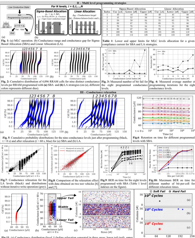
II. MULTI LEVEL PROGRAMMING STRATEGIES
To realize RRAM with multiple conductance levels, we rely on an iterative programming scheme (Fig. 1(a)), and on two different conductance allocation strategies to define the conductance ranges for the different levels: a) Sigma-Based Allocation (SBA) and b) Linear Allocation (LA) (Fig 1(b)). The SBA uses the standard deviation of conductance values (referred to as sigma) to allocate the conductance ranges as proposed by [4]. This solution results on narrower bins on lower conductance and larger bins on higher conductance. The LA equally allocates the conductance ranges. MLC is achieved experimentally using a computer-in-the-loop with a fabricated array of 4,096 HfO2 based RRAM 1T1R planar structures [6]
to implement the iterative write operation at array level. Table 1 lists the target conductance ranges to program eight levels and the corresponding programming current, which is kept under 135 µA in order to minimize degradation during endurance cycling and to limit the area of the access transistor [8]. Fig. 2 shows the distributions of the 4,096 cells in nine conductance levels (eight-programmed levels plus Reset) with SBA (a) and LA (b) strategies. The reported results are consistent over different arrays places on different dies (Fig. 2a).
Fig. 3 shows the number of erroneous cells out of the 4,096 cells after programming using SBA and LA. The number of programming iterations required to achieve these results are shown in Fig. 4. SBA requires an average number of 10 iterations per level to achieve no bit fail. In contrast, for LA, few cells continue to be erroneous even after more than 20 iterations because the LA strategy results in most conductive levels having a narrow resistance window.
III. CONDUCTANCE RELAXATION
Fig. 5 shows the conductance distributions for the nine levels just after programming (t = 0, black) and after 60 seconds (blue) for SBA and LA. The conductance spreads towards both higher and lower values reducing the read margin and hindering the MLC programming. Fig. 6 shows the changes in the conductance values with time. We observe that the mean conductance values (thick lines) remain stable over time in agreement with previously published data [9]. To investigate the behavior at cell level, we show (Fig.7) the conductance values obtained with the MLC programming strategy (black points) and without iterative write operation (grey) after relaxation (t= 60 s) as a function of their initial value (t=0). The conductance relaxation renders the MLC programming ineffective for the lower conductance levels. To eliminate the
hypothesis that relaxation is an artifact due to a design problem the measurements were repeated on two different test vehicles (Fig. 8). To quantify the effect of the relaxation over time, BER per level is showed as a function of time in Fig. 9. The conductance relaxation occurs on the first seconds and the BER tends to remain stable after the first 60 s. Fig. 10 represents the maximum BER (the maximum BER among the individual BERs per level) as a function of the number of bit-per-RRAM for different relaxation times. These results confirm that the BER remains constant after the first 60 s. In order to assure a BER lower than 10-3, a maximum of 2 bits-per-RRAM can be
stored without overlap.
Fig. 11 investigates the impact of the initial conductance value and of the cell position on the conductance relaxation. The relaxation effect occurs randomly, which means that it is not possible to predict a cell that is likely to move to a higher or lower conductance.
Thanks to the low compliance current used to program the array (limited to 135 µA), we achieve up to 105 cycles until the
first stuck bit (hard fail) appears (Fig. 12).
IV. 3D MONOLITHICALLY INTEGRATED MULTIPLE
1T1R
3D-monolithic integration technology is based on stacking active device layers on top of each other with very small 3D contact pitch (similar to standard contact) [10] This integration strategy was adopted to fabricate a 3D monolithically integrated multiple 1T1R structures: a RRAM is connected to the top transistor and another to the bottom transistor (Fig. 13). The HfO2 based RRAM cells were fabricated into the BEOL of the
top tier and they have the same material system of the ones fabricated on the 1T1R planar structures. The top transistor is a FDSOI integrated in 65 nm design rule. A high-k/metal gate stack with raised source and drain integrated at low temperature is adopted in order to preserve the bottom level. Two ebeam lithographic levels were developed and integrated in order to process the top RRAM above the first level of contacts and the second level of contacts aligned on the first one.
Fig. 14 shows the top and bottom layout schematic of the 3D monolithically integrated multiple 1T1R bitcell for a 28 nm technology node. Bit per surface ratio is increased by 1.5x with respect to a planar 1T1R structure at the same technology node. Fig.15 shows the endurance capability up to 105 cycles for the
bottom and top levelof a single 3D monolithically integrated multiple 1T1R: the distributions refers to multiple cycles of the top and bottom levels. The conductance modulation as a function of the programming current is showed in Fig. 16. The bottom and top levels have same electrical behavior.
We combined the MLC programming strategy (Section III) with our novel 3D-monolithically integrated multiple 1T1R structures to increase bit density. Fig. 17 shows the distributions of the 20 RRAM cells cycled 10 times in nine conductance levels (eight programmed levels plus reset state) for the top (red) and bottom (black) level. Conductance levels are the same as presented on Table I. Planar and 3D monolithically integrated 1T1R structures show the same behavior (Fig. 18).
V. NEUROMORPHIC APPLICATIONS
To study the impact of MLC and conductance relaxation on inference in hardware NN we used a Fully Connected (FC) NN trained on the MNIST and ECG [11] dataset (Fig 19). For the ECG database, the heartbeats are sliced in 700 ms time-series and a fast Fourier transform is used to extract 64 features, which are used as the NN input. Fig. 20 illustrates the training flowchart. First, a FCNN model is trained ex-situ using Tensor Flow and the outputs are the desired weights (wt). Then the
determined weights are transferred to two conductance values (G+ and-G). Since the conductance levels are programmed to
specific levels as described in the previous sections, a weight transfer error occurs between wt and the obtained weight (Fig.
20 bottom left shows an example of measured colormap of the weight transfer error). Therefore, the conductance allocation strategy affects the weight transfer error and consequently the NN accuracy. Fig.21 shows the impact of LA and SBA levels on the weight distributions taking into account the conductance relaxation effect. Conductance levels programmed with LA causes the weights distribution to be approximately uniform [1, 10] while SBA conductance results in overlapped weights. Fig.22 shows the accuracy for MNIST and ECG datasets as a function of the number of conductance levels per RRAM programmed with LA and SBA. SBA allows an improvement in accuracy for both MNIST and ECG data sets. MLC programming improves the NN accuracy despite the increase of the BER (Fig. 10). Moreover, MLC reduces the accuracy drop on small NN (Figs. 23 and 24).
Fig.25 shows the impact of conductance relaxation on accuracy for the MNIST and ECG dataset. To perform this task, the same data presented on Fig.10 is used. Despite the strong effect on BER, the conductance relaxation has a negligible effect on the system accuracy over time, especially for the MNIST application.
VI. CONCLUSIONS
In this work, we demonstrate that the combination of novel 3D monolithically integrated multiple 1T1R cells with MLC programming allows up to 4.75x higher density with respect to binary planar 1T1R cells. By means of extensive characterization at array level, we demonstrated that conductance relaxation after MLC programming is the limiting factor for storage applications rather than device-to-device or cycle-to-cycle variations limiting storage to 2-bit per RRAM. NN inference is resilient to relaxation and therefore it is advantageous to program nine conductance levels per RRAM (equivalent to 3.17 bits).
Acknowledgment: This work is supported by the ECSEL TEMPO project (826655) and the ANR grant NEURONIC (ANR-18-CE24-0009).
REFERENCES:[1] A. Valentian et al., IEDM, 2019. [2] T. F. Wu. Et al, ISSCC, 2019. [3] D. Alfaro et al, IEDM, 2019. [4] E.R. Hsieh et al., IEDM, 2019. [5] Q. Le Binh et al., TED, 2019 [6] A. Grossi et al., TED, 2019. [7] M. Bocquet et al., IEDM, 2018 [8] J. Sandrini et al., IEDM, 2019. [9] P. Yao et al., Nature, 2019. [10] L. Brunet et al., VLSI, 2016. [11] G. B. Moody et al., MBM, 2001.
II – Multi level programming strategies
III – Conductance relaxation
Table 1: Lower and upper limits for MLC levels allocation for a given compliance current for SBA and LA strategies.
Fig. 4: Measured average number of programming iterations for the eight conductance levels.
Fig.7: Conductance relaxation for the LA levels (black) and distributions without iterative write operation (grey).
Fig.8: Comparison of the relaxation effect with data obtained on two test vehicles [6] and [7].
Fig.12: Soft and hard fail positions for SBA strategy after 103, 104 and 105 endurance cycles (a, b, c
respectively).
(a)
(b)
(c) Fig.6: Retention on time for different programmed levels with SBA.
Fig. 5: Cumulative probability distributions for the nine conductance levels just after programming (black, t = 0 s) and after relaxation (t = 60 s, blue) for (a) SBA and (b) LA.
(a) (b)
Fig. 1: (a) MLC operation. (b) Conductance range and conductance gap for Sigma-Based Allocation (SBA) and Linear Allocation (LA).
Fig. 3: Measured number of bit fail for the eight programmed conductance levels.
(b) (a)
(b) (a)
Fig. 2: Cumulative distribution of 4,096 RRAM cells for nine distinct conductance levels per RRAM programmed with (a) SBA and (b) LA strategies (on (a), different colors represents different dies).
Fig.9: BER on time for the eight levels programmed with SBA (Table 1 level indexes on the figure).
Fig.11: (a) Conductance distribution (level 1) before relaxation separated in three areas: lower tail (red), upper tail (blue) and central zone (black). (b) Effect of the conductance relaxation for the three areas. Conductance relaxation is independent of the initial conductance value. The cells are separated in three zones according to the conductance value at after relaxation: stable cells (44 µS <G< 50 µS, at t=60 s) and cells drifting toward lower (G< 44 µS, at t=60s) and higher (G> 50 µS, at t=60s) conductance values. (c) Position of three areas on the 4 kb array. Conductance relaxation is independent of cell location on the array.
Q (b)
(a) (c)
Fig.10: Maximum BER on time for different number of bit-per-cell for different relaxation times.
IV – 3D monolithically integrated multiple 1T1R
V – Neuromorphic Applications
Fig.15 Conductance distribution after different number of endurance cycles for both top and bottom layers.
Fig.14: Top and bottom level layout schematic of 3D monolithically integrated multiple 1T1R structure for a 28 nm technology. Bit per surface ratio increases by 1.5x with respect to a planar 1T1R structure in the same technology node.
Fig.25: Accuracy versus time. The network is resilient to RRAM relaxation. Fig.19: Fully Connected (FC) network architecture
trained on MNIST and ECG dataset. Hidden layer 1 (H1) and 2 (H2) size: 150 and 75 for the MNIST data set and 32 and 16 for the ECG data set.
Fig.20: Flowchart of the training method: i) A model is trained ex-situ using TensorFlow; ii) The output are the desired weights (wt); iii) Weights are transfered to 2 conductances (wt=G+-G-); iv) The transfered weights
are stored into an array. Measured colormap of the weight-transfer error compared with the target values.
Fig.21: Conductance distribution (G+ and G-) and corresponding weights (wt = G+-G-) allocation using the LA (a) and SBA (b) strategies. Weights and conductance
distribution are showed before (t=0 s, black) and after (t = 60 s, blue) conductance relaxation.
Fig.18: Conductance distribution of 20 cells cycled 10 times with 3D integration (red is top, blue is bottom) and of 4,096 planar 1T1R cell (black). Fig.17: Cumulative distribution of 20 RRAM cells cycled 10 times measured
on the Top (red) and Bottom (black) ties. (a) SBA and (b) LA strategies. Fig.16: Conductance modulation as a
function of the programming current Top (red) and Bottom (black) tiers (b).
Fig.22: Accuracy versus number of levels per RRAM programmed with SBA and LA strategies. Multi level programming improves accuracy.
Fig.23: Accuracy versus number of levels per RRAM for two network size (number of neurons). MLC reduces the accuracy drop on small networks.
Fig.24: Accuracy dependence on the number of RRAM, number of neurons (sum of H1 and H2) for the ECG dataset.
(a) (b)
Fig.13: TEM cross-section of the 3D-monolithic integration with two CMOS layers and two TiN/HfO2/Ti/TiN-RRAM cells.