HAL Id: hal-00438857
https://hal.archives-ouvertes.fr/hal-00438857
Submitted on 4 Dec 2009
HAL is a multi-disciplinary open access
archive for the deposit and dissemination of
sci-entific research documents, whether they are
pub-lished or not. The documents may come from
teaching and research institutions in France or
abroad, or from public or private research centers.
L’archive ouverte pluridisciplinaire HAL, est
destinée au dépôt et à la diffusion de documents
scientifiques de niveau recherche, publiés ou non,
émanant des établissements d’enseignement et de
recherche français ou étrangers, des laboratoires
publics ou privés.
Graphical simulation of the dynamic evolution of the
software architectures specified in Z
Riadh Ben Halima, Mohamed Jmaiel, Khalil Drira
To cite this version:
Riadh Ben Halima, Mohamed Jmaiel, Khalil Drira. Graphical simulation of the dynamic evolution
of the software architectures specified in Z. 8th International Workshop on Principles of Software
Evolution, Sep 2005, Lisbon, Portugal. pp.4. �hal-00438857�
Graphical simulation of the dynamic evolution of the software architectures
specified in Z
Riadh Ben Halima, Mohamed Jmaiel
University of Sfax
National School of Engineers
B.P.W, 3038 Sfax, Tunisia
E-mail: {Riadh.BenHalima, Mohamed.Jmaiel}@enis.rnu.tn
Khalil Drira
LAAS-CNRS
7 avenue de Colonel Roche
31007 Toulouse Cedex 4, France
E-mail : [email protected]
Abstract
This paper provides a graphical simulator that enables to apprehend the dynamic of components-based software architectures based on their formal specification. The sim-ulator initially accepts (as an input) an already validated Z specification using the Z/EVES tool. Then, it gener-ates graphical entities, according to the UML notation, representing software’s components and their connectors. Thereafter, the user may generate architecture instances by adding components and connections between them. Ar-chitecture instances can be updated by destroying compo-nents/connections or by modifying their interconnections. The user actions are checked through the formal specifica-tion of the architectural style.
1
Introduction
The architecture of a software system is its ”style and method of design and construction” [4]. A software system with dynamic architecture are adaptable applications whose architecture evolves during their execution. The evolution of a dynamic architecture results from the addition or the removal of components and connections between them, and from the modification of interconnections as described in [5, 7]. Designing, this kind of applications is considered as a complex task which requires a rigourous specification of the corresponding architecture and its evolution.
In this work, we use formal methods for describing dy-namic software architectures. We employ the Z notation [9] to specify architectural styles as well as configuration operations. The use of the formal approach allows us to rigourously reason about architectural properties and to prove that the architectural style is preserved during the plication execution. In order to consolidate this formal ap-proach, we design and implement a graphical tool that
en-ables to apprehend the formal specification (written in Z) of an architecture. This tool parses Z specifications and allows to identify the elements of its architectural style as well as the pre- and the post-conditions associated to a reconfigura-tion operareconfigura-tion. Moreover, it permits to generate diagram-matically architecture instances, using UML 2.0 notation [3], which respect the specified architectural style. Also, we integrate our simulator with the Z/EVES tool [8] which allows to edit, to check and to prove Z specification. Across its graphic interface, the simulator allows to the designer, who does not necessarily master formal specifications, to understand the behaviour of the system to build.
This paper is organized as follows. Section 2 gives a sur-vey on the related work. Section 3 introduces the approach of the dynamic architectures description using Z. Section 4 presents the features and the design of our simulator. The last section concludes the paper.
2
Related works
Currently, the Unified Modelling Language (UML) is ac-cepted as a standard for designing software applications. Its set of notations helps system designers to represent their solutions in a way that is expressive and yet easy to under-stand. However, UML is generally criticized for the lack of means for verifying and validating the designed mod-els. The advantage of our approach appears in its capacity to produce a formal model presented to the user according to the UML visual notations during the simulation process. So, on one hand, contrary to an approach using only the for-mal, we suppose that the user of our environment does not need to be an expert in formal methods. On the other hand, we do not reduce the rigourous capacity of our model by limiting us to the informal side, using only the UML nota-tions.
Several research works choose the use of formal meth-ods for specifying dynamic software architectures. Among
these works, we mention the CHAM [10] approach which is based on grammars and rewriting rules. This approach uses reactions and evolutions to formalize, respectively, ar-chitectural styles and reconfigurations. However, We note the lack of tools for validating or simulating specifications developed according to this approach. Other approaches, like LEDA [2] and Wright [1] make use of process algebra to specify dynamic software architectures. Wright presents the structure of an architecture as a graph and specifies the system behaviour and reconfigurations using a variant of CSP. LEDA uses the π-calculus to describe dynamic archi-tectures. It supports prototype execution using a π-calculus analysis tool : the Mobility Workbench. Another widely rec-ognized approach is RAPIDE [6], in which a software archi-tecture consists of a set of module interfaces interconnected according to a set of connection rules and communication constraints. These prominent approaches, although they propose rigorous solutions for designing software architec-tures, they lack tools for simulation and animation of soft-ware architectures. RAPIDE is one of the few formalisms which enable the animation of a program behaviour in term of causal ordering of events.
On the other hand, there are several tools which tried to animate Z specifications, namely, Jaza (Just Another Z Animator), PiZA (A Z Animator which is implemented in Prolog) and ZANS (Z ANimator System). Firstly, Jaza is used to evaluate the schemas of a Z specification. How-ever, it presents some drawbacks. Among his limits, we can appoint : the absence of the treatment of all the Z lan-guage constituents (e.g. generic definitions and axiomatic declarations), the impossibility of declaring the functions or relations infixed, prefixed and postfixed. Then, PiZA al-lows the conversion of restricted parts of a Z specification into Prolog and their execution. It is hard to use because it requires the installation of other software and contains at least two translation stages. Finally, ZANS permits the evaluation of expressions and predicates and the execution of operation schemas. It allows animating finite subsets of Z specifications. Nevertheless, a formal specification anima-tor executes and interprets traces on a specification. Thus, animation can only show the presence of errors, never their absence. Whereas, the visual simulation displays the spec-ification lacks and deficits and gives more chance to fix er-rors.
3
Specification of dynamic architectures
Our work is based on the approach [5], which relies on the integration of graph grammars within the Z notation to describe the static and dynamic aspects of software archi-tectures. Its advantage is that it is expressive enough to deal with the static aspects (component types, connection types and architectural properties) as well as the dynamic
aspects (reconfiguration operations) of an architecture. This approach aims, mainly, at guaranteeing the preservation of architectural properties during the system evolution. Ac-cording to this approach, the architectural style of a soft-ware system is described using a Z schema as follows :
Style
Component types Connection types Architectural properties
Schema 1: Architectural style
To give more details on our approach, we present in this section a simple example. The Patient Monitoring System (PMS), which was used to illustrate work of [7]. It is a soft-ware system which let the nurses (of type NURSE) control-ling their remote patients in a private clinic. A controller (of type BED MONITOR) is attached to the bed of the patient.
PMS
CN : F NURSE
PB : F BED MONITOR ES : F EV SER
pull NE : NURSE ↔ EV SER
pull EB : EV SER ↔ BED MONITOR push BE : BED MONITOR ↔ EV SER push EN : EV SER ↔ NURSE
#ES <= 3
CN = dom pull NE ES = ran pull NE ES = dom pull EB PB = ran pull EB PB = dom push BE ES = ran push BE ES = dom push EN CN = ran push EN ∀ s : ES • #{(ran({s} C push EN ))} ≤ 5 ∀ b : ES • #{(ran({b} C pull EB))} ≤ 15 ∀ x : PB • ∃1y : ES • (x , y) ∈ push BE ∀ x : PB • ∀ y : ES • ∃ z : CN • (x , y) ∈ push BE ⇒ (y, z ) ∈ push EN
∀ x : CN • ∃1y : ES • (x , y) ∈ pull NE
Schema 2: PMS schema
For each service of the private clinic (pediatric, cardiol-ogy, maternity...), we associate an event service (of type
EV SERV) to manage the communications between nurses
and bed monitors (when necessary). The architectural style is represented by schema 2.
In the first part this schema, we develop a declaration part which specifies component types as well as connec-tion types being able to exist between them. In this specifi-cation, CN, PB and ES represents respectively the nurses, the bed monitors and the event services. This part inte-grates also relations representing the communication links
between the components. In addition to the architectural style constraints, an application can have specific properties which must be satisfied during the evolution of its archi-tecture. We will take some properties of the PMS system, which are formulated in the second part of schema 2, such:
• The system must contain a maximum of 3 services. • A service contains a maximum of 5 nurses and 15
pa-tients.
• A nurse must be connected to only one service. According to the approach presented in [5], the dynamic part of an architecture is described using ∆ (Delta) Z schemas (cf Schema 3). Indeed, each ∆ schema represents a reconfiguration operation.
Operation Name ∆Style
Par1?;Par2?;....;Parn?
Pre-conditions Post -conditions
Schema 3: A Delta schema
Where Pari? denotes an input of the operation. The
PMS specification presents different operations of reconfig-uration that make possible system evolution. The recon-figuration is then performed if the functional and structural constraints are satisfied. For example, the Insertion of an
event-service operation (cf Schema 4) inserts an instance
of a component of type EV SER provided that the system does not already contain three event services according to the first predicate in the PMS schema.
insert ES ∆PMS x ? : EV SER #ES < 3
ES0= ES ∪ {x ?}
Schema 4: Insertion of an event-service
We used the Z/EVES tool [8] to edit and check the syn-tax of the PMS specification as well as to prove that the specified reconfiguration operation preserve the architec-tural style. Indeed, if we start from a configuration which satisfies the architectural style and we apply an operation of reconfiguration to the latter, we obtain a new configuration which also satisfies the architectural style. Formally and in the case of the PMS specification, this is translated in the following theorem:
∀ pms ∈ PMS , ∀ op ∈ Op PMS , pms ∧ op ⇒ pms0
∧ (pms0
satisfy the PMS pre-conditions)
With, Op PMS=insert ES, insert CN, insert PB, supp PB,
supp CN, supp ES;
With Z/EVES, the demonstration of this theorem corresponds to demonstrate six sub-theorems where each considers an tion from the set Op PMS. For example, for the insert ES opera-tion, it is necessary to demonstrate the following theorem:
theorem Verif insert ES
PMS ∧ insert ES ⇒ PMS0∧ (PMS0⇒ pre PMS )
This theorem, proved by Z/EVES, shows that the initial architec-tural style is preserved. The following section debates the visual simulation of a Z specification.
4
The simulator : presentation and features
The simulator is a generic application which simulates the functioning mode of component-based applications. It rep-resents components and connections using UML 2.0 conven-tions. Moreover, it provides the possibility of adding and/or re-moving components and connections. Each reconfiguration ac-tion (adding/removing) proceeds while respecting its descripac-tion within the Z notation, according to the approach presented in Sec-tion 3. The main interface of the simulator (figure 1) contains menus, a toolbox and a drawing panel.Figure 1. The simulator GUI
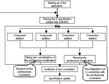
We group in figure 2 the different operating scenarios of our simulation environment. Its use proceeds according to following phases :
1. The start up of the simulator.
2. The user commands to the simulator to read the specification (with the Z notation) to simulate.
3. The simulator parses the specification in order to extract the architectural style (the types of components and connections, as well as the constraints) and to list the reconfiguration op-erations.
4. The simulator prepares the toolbox (for each component or connection type corresponds a button).
5. The simulation of reconfigurations: the user press on a but-ton in the toolbox (which represents a component type or a connection type) and clicks on the drawing panel in order to represent graphically the component chosen according to the UML 2.0 notation.
6. The simulator checks the compatibility of each reconfigura-tion with the architectural style. If it generates an architec-ture instance which respects the style, it executes the recon-figuration, otherwise it breaks it.
7. If during simulation the user detects a case which does not comply with the requirements, then we are brought to the initial Z specification. To take into account of the new syn-thesized property, we use the command Update of the menu
Rule. Thus we put the new changes into practice.
Figure 2. Functional scenario
Our simulator examines and translates the architectural prop-erties into a set of constraints to be respected by the user during the simulation of a reconfiguration. If an operation does not obey the constraints, the simulator prohibits it while showing an error message. For example, when we begin with a configuration that contains three events services and we want to add the fourth, we creates an inconsistent state (because # ES <= 3). Therefore, our simulator ignores this reconfiguration. Also, we cannot bind two components as long as there is no connection specified in the archi-tectural style between them. For example, it is impossible to bind a nurse with a bed monitor because no relation between them is specified. Additionally, we can update the specification whenever
we want to satisfy user’s need. An example in the case of PMS: Due to the small number of patients, the clinic manager wants to reduce the expenses. He wants to limit the nurses’s number to twenty. To allow the taking into account of the new rule (in the Z specification), we add the following line to the architectural prop-erties of PMS : |# CN < 20. To forbid the simulation of such con-figuration, the simulation must reload the modified specification with the update command. After that, the simulator prohibits any configuration to simulate with a nurses number superior to twenty.
3.
5
Conclusion
Our purpose in this paper is to provide to the designers a visual tool that allows to conceive UML2.0 diagram of a system accord-ing to his formal specification with the Z notation. The interest of this environment is to enable designers, who are not familiar with formal techniques, to better understand the architectural properties of the system formally specified with Z. The graphic visualization of an erroneous configuration helps to identify the specification defects and to rectify them.
In perspective, we intend to take into account the behaviour of components. For that goal, we envisage the integration of a formal language which supports the description of processes such as process algebra.
References
[1] R. Allen, R. Douence, and D. Garlan. Specifying and
an-alyzing dynamic software architectures. Lecture Notes in
Computer Science. 1998.
[2] C. Canal, E. Pimentel, and J. M. Troya. Specification and refinement of dynamic software architectures. In In Software
Architecture, pages 107–126. Kluwer Academic Publishing,
February 1999.
[3] O. M. Group. Uml superstructure 2.0 - draft adopted speci-fication. 2003.
[4] B. Hayes-Roth, K. Pfleger, P. Lalanda, P. Morignot, and M. Balabanovic. A domain-specific software architecture for adaptive intelligent systems. IEEE Trans. Softw. Eng., 21(4):288–301, 1995.
[5] I. Loulou, A. H. Kacem, M. Jmaiel, and K. Drira. Toward a unified graph-based framework for dynamic component-based architectures description in z. In ACS/IEEE
Interna-tional Conference on Pervasive Services ICPS’04, 2004.
[6] D. C. Luckham, J. L. Kenney, L. M. Augustin, J. Vera, D. Bryan, and W. Mann. Specification and analysis of sys-tem architecture using rapide. In IEEE Trans. on Software
Engineering, volume 21, pages 336–355, 1995.
[7] D. L. M´etayer. Describing software architecture styles using graph grammars. IEEE Transactions on Software
Engineer-ing, 24(7):521–553, July 1998.
[8] ORA. Z/eves. http://www.ora.on.ca/Z-eves.
[9] J. Spivey. The Z Notation : a Reference Manual, Series in
Computer Science. Prentice-Hall, 1992.
[10] J. Vera, L. Perrochon, and D. C. Luckham. Event-based ex-ecution architectures for dynamic software systems. In the
Working IFIP Conf. on Software Architecture, pages 22–24,