HAL Id: tel-00507482
https://tel.archives-ouvertes.fr/tel-00507482
Submitted on 30 Jul 2010HAL is a multi-disciplinary open access
archive for the deposit and dissemination of sci-entific research documents, whether they are pub-lished or not. The documents may come from teaching and research institutions in France or abroad, or from public or private research centers.
L’archive ouverte pluridisciplinaire HAL, est destinée au dépôt et à la diffusion de documents scientifiques de niveau recherche, publiés ou non, émanant des établissements d’enseignement et de recherche français ou étrangers, des laboratoires publics ou privés.
A DL-Based Approach to Integrate Relational Data
Sources into the Semantic Web
Thi-Dieu-Thu Nguyen
To cite this version:
Thi-Dieu-Thu Nguyen. A DL-Based Approach to Integrate Relational Data Sources into the Semantic Web. Human-Computer Interaction [cs.HC]. Université Nice Sophia Antipolis, 2008. English. �tel-00507482�
Sciences et Technologies de l’Information et de la Communication
THESE
pour obtenir le titre de DOCTEUR EN SCIENCESde l’UNIVERSITE de Nice-Sophia Antipolis Sp´ecialit´e: Informatique
pr´esent´ee et soutenue par Thi Dieu Thu NGUYEN
A DL-BASED APPROACH TO
INTEGRATE RELATIONAL DATA SOURCES
INTO THE SEMANTIC WEB
Th`ese dirig´ee par Nhan LE-THANH soutenue le 5 mai 2008
Jury:
M. Michel RIVEILL Professeur `a l’UNSA Pr´esident
M. Jacques LE MAITRE Professeur `a l’Universit´e du Sud Toulon-Var Rapporteur M. Franck MORVAN Maˆıtre de Conf. `a l’Universit´e de Toulouse 3 Rapporteur Mme. Zohra BELLAHSENE Professeur `a l’Universit´e de Montpellier II Examinateur
M. Peter SANDER Professeur `a l’UNSA Examinateur
The Semantic Web is a new Web paradigm that provides a common framework for data to be shared and reused across applications, enterprises and community boundaries. The biggest problem we face right now is a way to “link” information coming from different sources that are often heterogeneous syntactically as well as semantically. Today much information is stored in relational databases. Thus data integration from relational sources into the Semantic Web is in high demand. The objective of this thesis is to provide methods and techniques to address this problem. It proposes an approach based on a combination of ontology-based schema representation and description logics. Database schemas in the approach are designed using ORM methodology. The stability and flexibility of ORM facil-itate the maintenance and evolution of integration systems. A new web ontology language and its logic foundation are proposed in order to capture the semantics of relational data sources while still assuring a decidable and automated reasoning over information from the sources. An automatic translation of ORM models into ontologies is introduced to allow capturing the data semantics without laborious-ness and fallibility. This mechanism foresees the coexistence of others sources, such as hypertext, integrated into the Semantic Web environment.
This thesis constitutes the advances in many fields, namely data integration, on-tology engineering, description logics, and conceptual modeling. It is hoped to provide a foundation for further investigations of data integration from relational sources into the Semantic Web.
iii
Keywords: Data Integration, Semantic Web, Web Ontology Languages, Descrip-tion Logics, Automated Reasoning, Tableau Algorithms, Conceptual Modeling.
Le web s´emantique est un nouveau paradigme web qui fournit un cadre com-mun pour des donn´ees devant ˆetre partag´ees et r´eutilis´ees `a travers des applica-tions, en franchissant les fronti`eres entre les entreprises et les communaut´es. Le probl`eme majeur que l’on rencontre `a pr´esent, est la mani`ere de relier les infor-mations provenant de diff´erentes sources, celles-ci utilisant souvent une syntaxe et une s´emantique diff´erentes. Puisqu’aujourd’hui, la plupart des informations sont gard´ees dans des bases de donn´ees relationnelles, l’int´egration de source de donn´ees relationnelle dans le web s´emantique est donc tr`es attendue.
L’objectif de cette th`ese est de fournir des m´ethodes et des techniques pour r´esoudre ce probl`eme d’int´egration des bases de donn´ees. Nous proposons une approche combinant des repr´esentations de sch´emas `a base d’ontologie et des logiques de descriptions. Les sch´emas de base de donn´ees sont con¸cus en utilisant la m´ethodologie ORM. La stabilit´e et la flexibilit´e de ORM facilite la maintenance et l’´evolution des syst`emes d’int´egration. Un nouveau langage d’ontologie web et ses fondements logiques sont propos´ees afin de capturer la s´emantique des sources de donn´ees relationnelles, tout en assurant le raisonnement d´ecidable et automa-tique sur les informations provenant des sources. Une traduction automatis´ee des mod`eles ORM en ontologies est introduite pour permettre d’extraire la s´emantique des donn´ees rapidement et sans faillibilit´e. Ce m´ecanisme pr´evoit la coexistence d’autre sources d’informations, tel que l’hypertexte, int´egr´ees `a l’environnement web s´emantique.
Cette th`ese constitue une avanc´ee dans un certain nombre de domaine, notamment dans l’int´egration de donn´ees, l’ing´enierie des ontologies, les logiques de descrip-tions, et la mod´elisation conceptuelle. Ce travail pourra fournir les fondations pour d’autres investigations pour int´egrer les donn´ees provenant de sources rela-tionnelles vers le web s´emantique.
v
Mots-cl´es: Int´egration de donn´ees, Web s´emantique, Langages d’ontologie web, Logiques de Descriptions, Raisonnement automatique, Algorithmes de Tableau, Mod´elisation conceptuelle.
List of Tables xiii
List of Figures xviii
1 Introduction 2
1.1 Motivation . . . 2 1.1.1 Challenges of Semantic Integration into the Semantic Web . 3 1.1.2 Objectives and Approach . . . 4 1.2 Scope and Limitations . . . 5 1.3 Thesis Outline . . . 6
2 Data Integration and Conceptual Data Modeling 8
2.1 Information Integration and Data Integration . . . 9 2.1.1 Data Integration based on Peer-to-Peer Architecture . . . . 10 2.1.2 Data Integration based on Mediated Schema . . . 11 2.1.3 Procedural and Declarative Approach . . . 12
CONTENTS vii
2.2 Conceptual Modeling and Reasoning Advantages . . . 13
2.3 Conceptual Data Modeling . . . 15
2.3.1 Categories of Data Models . . . 16
2.3.2 Entity-Relationship Model . . . 19
2.3.3 UML Class Diagram . . . 20
2.3.4 Object Role Modeling . . . 22
2.3.5 Distinguish ORM from ER modeling and UML class dia-gramming . . . 24
2.4 Conclusion . . . 31
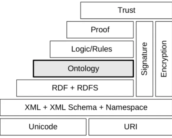
3 Ontology Technology and Data Integration into Semantic Web 34 3.1 Semantic Web Environment . . . 35
3.1.1 Semantic Web Architecture . . . 35
3.1.2 Ontology and Web Ontology languages . . . 38
3.2 Web Ontology Language OWL . . . 42
3.3 Description Logics . . . 44
3.3.1 Syntax and Semantics . . . 46
3.3.2 Reasoning Services . . . 51
3.3.3 Reasoning Algorithms . . . 53
3.4 Integrating Relational Data Sources into the Semantic Web . . . 55
3.4.1 Query-based Approach . . . 55
3.4.2 Semantic Annotation Approach . . . 60
3.5 Conclusion and Proposition . . . 66
4 Web Ontology language OWL-K 72 4.1 Overview of OWL DL Language . . . 73
4.1.2 Syntax and Semantics . . . 75
4.2 OWL DL with Identification Constraints . . . 79
4.3 Modeling ICs in OWL-K . . . 82
4.3.1 Vocabulary . . . 82
4.3.2 Abstract Syntax . . . 84
4.3.3 RDF Graphs . . . 85
4.4 SHOIN K(D) - Logic Foundation of OWL-K . . . . 85
4.4.1 Representation of Identification Constraints in DLs . . . 86
4.4.2 Universal Concrete domain . . . 89
4.4.3 SHOIN K(D) Syntax and Semantics . . . . 90
4.5 Conclusion . . . 94
5 Reasoning for OWL-K 96 5.1 General Method of Tableau Algorithms . . . 97
5.2 A Tableau for SHOIQK(D) . . . . 101
5.3 Constructing a SHOIQK(D)-Tableau . . . . 107
5.3.1 Blocking and Merging . . . 108
5.3.2 Prerequisite . . . 110
5.3.3 ICs and Problems in Constructing a SHOIQK(D)-Tableau 115 5.3.4 Algorithm . . . 120
5.3.5 Concrete Domain and Reasoning Procedure . . . 124
5.4 Properties of the Algorithm . . . 125
5.4.1 Termination . . . 125
5.4.2 Soundness . . . 129
5.4.3 Completeness . . . 134
CONTENTS ix
5.5 Related Work . . . 139
5.6 Conclusion . . . 141
6 Modeling ORM schemas in OWL-K 144 6.1 Data Modeling in ORM . . . 145
6.1.1 Conceptual Schema Design Procedure . . . 145
6.1.2 ORM Diagrams . . . 147
6.2 Basic Components . . . 150
6.2.1 Value Types . . . 150
6.2.2 Entity Types . . . 151
6.2.3 Predicates and Roles . . . 152
6.3 Object Constraints . . . 155
6.3.1 Value Constraints . . . 155
6.3.2 Subtypes and Supertypes . . . 157
6.3.3 Exclusion and Exhaustion Constraints . . . 158
6.4 Role Constraints . . . 160
6.4.1 Mandatory Constraints . . . 160
6.4.2 Internal Uniqueness Constraints . . . 163
6.4.3 Frequency Constraints . . . 166
6.4.4 Simple Reference Schemes . . . 168
6.4.5 External Uniqueness Constraints . . . 169
6.4.6 Nested Object Types . . . 174
6.4.7 Set-comparison Constraints . . . 177
6.4.8 Ring constraints . . . 184
6.5 Mapping Algorithm . . . 186
6.5.2 Mapping Predicates and Roles . . . 189
6.5.3 Mapping Constraints . . . 189
6.5.4 Mapping Procedure . . . 191
6.6 Conclusion . . . 192
7 Implementation Exploit Information from RDB in Semantic Web 194 7.1 Illustration Example . . . 194
7.2 Relational Mapping . . . 195
7.3 ORM diagrams in XML structure . . . 198
7.4 Generating Ontologies . . . 200
7.4.1 OWL-K ontologies . . . 200
7.4.2 Orm2OwlK Tool . . . 201
7.5 Conclusion . . . 204
8 Conclusion and Perspectives 206 8.1 Thesis Overview . . . 206
8.2 Main Contributions . . . 207
8.2.1 Contributions to the Advances in Data Integration . . . 208
8.2.2 Contributions to the Advances in the Theory of Description Logics . . . 210
8.2.3 Contribution to Web Ontology Language Development . . . 211
8.2.4 Contribution to the Advances in the Theory of Conceptual Modeling . . . 212
8.3 Open Problems and Future Work . . . 212
8.3.1 Concrete Domains for SHOIQK . . . . 212
CONTENTS xi
8.3.3 Implementation, Evaluation, and Optimization of Reasoning Procedure . . . 213 8.3.4 IC Representation in DLs and Web Ontology Languages . . 214 8.3.5 ORM Schema Representability in Web Ontology Languages 214 8.3.6 Further Steps in Building a Data Integration System . . . . 216
A DDL Script from ORM Schema 218
B ORM Schema in XML 220
C RDF Schema of OWL-K 230
D ORM Schema in OWL-K Ontology 232
D.1 OWL-K Ontology in Abstract syntax . . . 232 D.2 OWL-K Ontology in RDF/XML syntax . . . 234
2.1 Some data of the department employment . . . 23
3.1 Syntax and Semantics of concept descriptions in ALC language . . 47
3.2 Classes in Relational.OWL language . . . 63
3.3 Properties in Relational.OWL language . . . 64
3.4 Advantages of our proposition over existing works in semantic an-notation approach . . . 69
4.1 OWL DL data ranges . . . 75
4.2 OWL DL class, property descriptions . . . 76
4.3 OWL DL axioms and facts . . . 77
4.4 Vocabulary extension for OWL-K . . . 84
4.5 Transformation of IC assertion to triples . . . 85
4.6 SHOIN K(D) role syntax and semantics . . . . 90
4.7 SHOIN K(D) concept syntax and semantics . . . . 92 4.8 Mapping from OWL-K abstract syntax to DL syntax and semantics 92
LIST OF TABLES xiii
5.1 Qualified number restrictions in SHOIQK(D) . . . . 97
5.2 The tableau expansion rules for ALC . . . . 99
5.3 NNF rewrite rules for SHOIQK(D) . . . . 101
5.4 Merging mechanism for SHOIQ . . . . 110
5.5 The tableau expansion rules for SHOIQ . . . . 115
5.6 Additional tableau expansion rules for SHOIQK(D) . . . . 122
5.7 Reasoning procedure for SHOIQK(D) . . . . 124
6.1 The conceptual schema design procedure . . . 146
6.2 Mapping rules in DL and OWL-K abstract syntax . . . 187
6.3 Mapping rules in DL and OWL-K abstract syntax (cont.) . . . 188
6.4 Mapping object types and reference modes . . . 189
6.5 Mapping predicates and roles . . . 190
6.6 Mapping constraints . . . 191
2.1 Peer-to-Peer data integration architecture . . . 10
2.2 Architecture of a data integration system based on mediated schema 11 2.3 A simple schema in physical model . . . 17
2.4 An example of the database schema in the logical model . . . 18
2.5 An example of the ER schema . . . 20
2.6 UML diagram of the example in Figure 2.5 . . . 21
2.7 Modeling the data of Table 2.1 in ORM . . . 24
2.8 An example illustrates the illogical attributes of an object in ER (UML) modeling . . . 26
2.9 An example illustrates the illogical entities in ER (UML) modeling 26 2.10 An example illustrates the instability of ER (UML) schemas . . . . 27
2.11 Constraintes in ORM (a) are described as an attached comment in UML (b) . . . 28
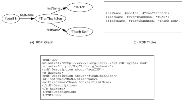
3.1 The basic layers of data representation for the Semantic Web . . . . 36 3.2 An example of RDF graph, its triples and RDF/XML serialization . 37
LIST OF FIGURES xv
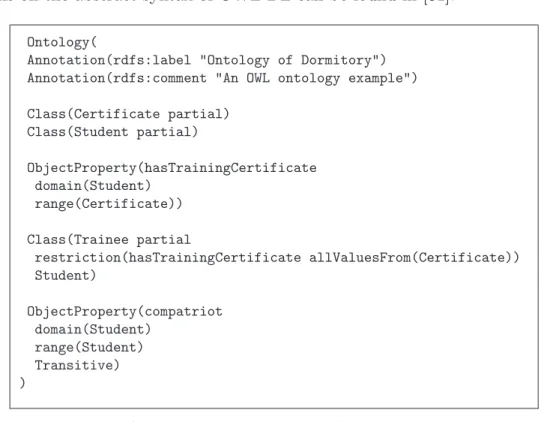
3.3 An OWL ontology in RDF/XML serialization . . . 45
3.4 A Tbox example . . . 49
3.5 An Abox example . . . 50
4.1 An example ontology in the OWL DL abstract syntax . . . 78
4.2 Examples showing the limitations of OWL DL in representing ICs . 80 4.3 Class Hierarchy for OWL-K . . . 83
5.1 A complete tree for ∃R.A) u (∃R.B) u ∀R.(¬A t ¬B) . . . . 100
5.2 A complete tree and model in the form of graph for the ALCHR+ -concept ∃R.C u ∀R.(∃R.C), R is a transitive role [76]. . . . 100
5.3 Pair-wise blocking . . . 109
5.4 A model of the concept ≥ 3U. <2 . . . 111
5.5 A graph illustrating the interaction between ICs and concrete domain112 5.6 A graph illustrating the interaction between ICs and unraveling . . 114
5.7 Illustration of IC satisfaction leads to blocking satisfaction . . . 116
5.8 Illustration of merging identified nodes leads to an invalid graph . . 117
5.9 Blocking cycles are broken . . . 118
5.10 Merging identified nodes without nominalization . . . 119
6.1 Symbolizing a fact . . . 147
6.2 Main symbols in ORM diagrams . . . 149
6.3 A value type represented in an ORM diagram . . . 150
6.4 VL-rule - Modeling value types in OWL . . . 151
6.5 EN-rule - Modeling entity types in OWL . . . 152
6.6 Example of modeling entity types in OWL . . . 152
6.7 Unary, binary and ternary predicates in an ORM diagram . . . 153
6.9 R1-rule - Modeling attributive roles in OWL . . . 154
6.10 R2-rule - Modeling non-attributive roles in OWL . . . 154
6.11 IR-rule - Modeling inverse roles in OWL . . . 155
6.12 VC1-rule - Modeling VCs on entity types in OWL . . . 156
6.13 VC2-rule - Modeling enumerated VCs on value types in OWL . . . 157
6.14 Modeling derived predicates with one asterisk in OWL . . . 158
6.15 ST-rule - Modeling subtypes and supertypes in OWL . . . 158
6.16 Modeling the mutual exclusion constraint in OWL . . . 159
6.17 Modeling the collective exhaustion constraint in OWL . . . 159
6.18 MC2-rule - Modeling MCs in binary predicates in OWL . . . 161
6.19 MC1-rule - Modeling MCs in unary predicates in OWL . . . 161
6.20 Modeling DMCs on two predicates in OWL . . . 162
6.21 DMC-rule - Modeling DMCs in OWL . . . 162
6.22 IUC1-rule - Modeling IUCs spaning one role in OWL . . . 164
6.23 IUC2-rule - Modeling pattern one-to-one of IUCs in OWL . . . 165
6.24 IUC3-rule - Modeling the many-to-many pattern of IUCs in OWL . 165 6.25 PIUC-rule - Modeling the preferred IUCs in OWL . . . 166
6.26 Example of using FCs in ORM . . . 167
6.27 Modeling FCs in OWL . . . 167
6.28 RS-rule - Simple reference scheme translation into OWL-K . . . 168
6.29 RM-rule - Reference mode translation into OWL-K . . . 169
6.30 The EUC describes no building name duplicated on the same campus169 6.31 Modeling IC patterns on two roles in OWL-K . . . 170
6.32 EUC1-rule Modeling IC patterns on n roles in OWL-K . . . . 171
LIST OF FIGURES xvii
6.34 PEUC-rule - Modeling IC patterns using the preferred EUCs in
OWL-K . . . 172
6.35 ORM schema equivalence . . . 173
6.36 Modeling EUCs on two roles for FDs in OWL-K . . . 173
6.37 EUC2-rule - Modeling EUCs for FDs in OWL-K . . . 174
6.38 An example illustrates the nesting of unary predicates . . . 175
6.39 NUP-rule - Modeling the nesting of a unary predicate in OWL-K . 175 6.40 An example illustrates the nesting of unary predicates without IUCs.176 6.41 NBP-rule - nesting of binary predicates without IUCs. . . 176
6.42 Examples showing nested object types split into simpler fact types. 177 6.43 Subset constraint describing projects having no end date without a start date. . . 178
6.44 SC1-rule - Modeling subset constraint between two roles in OWL. . 179
6.45 SC2-rule - Modeling subset constraint between two binary predi-cates in OWL. . . 179
6.46 Modeling equality constraints using the rules for subset constraints. 180 6.47 EQ1-rule - Modeling equality constraints between two roles in OWL 181 6.48 EQ2-rule - Modeling equality constraints between two predicates in OWL . . . 181
6.49 The population of Menu13E is not the population of FullMenu . . . 182
6.50 Modeling ECs on two predicates in OWL . . . 182
6.51 EC-rule - Modeling ECs on n roles of n predicates in OWL . . . . . 183
6.52 Exclusion constraints for sequences of roles . . . 183
6.53 General equality constraints in ORM . . . 184
6.54 Modeling ring constraints in OWL . . . 185
7.1 ORM schema example . . . 195
7.3 The XML schema for ORM diagrams in Orthogonal Toolbox . . . . 199 7.4 OWL-K ontology structure . . . 201 7.5 The interface 1 of Orm2OwlK . . . 203 7.6 The interface 2 of Orm2OwlK . . . 204 8.1 Integrating relational databases into the Semantic Web using
Introduction
1.1
Motivation
The information society requires full access to the available information, which is often distributed and heterogeneous. Traditional information systems, as well known, are built for that purpose by using some data models and databases. That means to access information from other sources (or systems), an information system must transfer the data formats of these sources to hers. This process is time-consuming and not always easy. Besides, data acquisition (although auto-matic or semi-autoauto-matic) requires inevitably a large investment on the technical infrastructure and/or manpower. The purpose of the integration is therefore to create a common gateway to sources heterogeneous and probably distributed. Continually, new applications are introduced in enterprises, while existing legacy applications cannot be replaced because of the investments that have been made in the past. These new applications need to use data residing in the legacy appli-cations, which is typically stored in a proprietary format. If a new application is to reuse the information residing in legacy systems, this information needs to be made available in a way that is understandable to the new application. Therefore, besides the differences in hardware and software platforms, not only the differ-ences in syntax, but also the differdiffer-ences in semantics need to be overcome. Since systems become more and more distributed and disparate within and across or-ganizational boundaries and market segments, semantic integration has become a much-debated topic and it is viewed as a solution provider in both industrial and
1.1 MOTIVATION 3
academic settings.
1.1.1
Challenges of Semantic Integration into the Semantic
Web
The emergence of the Semantic Web, and its anticipated industrial uptake in the years to come, has made the sharing of information easier to implement and deploy on a large scale in open distributed environments. Since much information on the web is generated from relational databases (the “deep web”), the recent call for the Semantic Web provides additional motivation for the problem of associating semantics with database-resident data. Therefore, it will be necessary to make existing database content available for emerging Semantic Web applications, such as web agents and services.
However, semantic integration of relational data sources into the Semantic Web is not a trivial task. There are (at least) three crucial issues must be considered:
• First, in the foreseeable future, databases, knowledge bases, the World Wide Web, and the Semantic Web will coexist. A challenge for current systems is to accommodate their contents, which are either defined by schemas based on structure or defined by ontologies based on semantics. Therefore, the integration should permit to handle heterogeneous sources generated by not only different data models for databases but also formalisms for other sources, e.g. hypertext. Besides, integration systems should have the capability of evolution and maintenance independently from the run-time characteristics of the underlying sources.
• Second, the design, exploitation and maintenance of such an integration sys-tem require reasoning support over information from all those sources. How-ever, database research mainly deals with efficient storage and retrieval with powerful query languages, and with sharing and displaying large amounts of documents while reasoning over the structure and the content of documents plays only a minor role.
• Third, the automation of processing data sources requires to clarify and for-malize the knowledge residing in databases. That is, there should have a mechanism specifying the communication/exchange protocol, the vocabu-laries used and the interpretation rules so that the data semantics can be captured correctly.
1.1.2
Objectives and Approach
The aim of this thesis is, therefore, to provide methods and techniques to solve the three above-mentioned issues. This aim is further developed into the following objectives:
1. To integrate resources from databases into the Semantic Web while guaran-teeing the semantic integration ability from various resources of the Semantic Web and the evolution and maintenance independently from the run-time characteristics of data sources. We focus on how to make database content available on the Semantic Web.
2. To identify the data model for databases that facilitates the integration re-garding the presented issues.
3. To add additional deductive capabilities to integration systems to increase the usability and reusability of data from relational databases.
4. To provide a mechanism to achieve the semantic transparence between data sources and the integration system. The knowledge representation of such a system should be unambiguous, supported by an inference engine, compati-ble to the standards of World Wide Web and at the same time should permit to capture the semantics of relational data sources.
To achieve those objectives, our approach is to combine ontology-based schema representation and description logics. In particular, our solutions are as follows.
• We use Semantic Web ontologies to incorporate database schemas. That is, data models of databases will be represented in Semantic Web ontologies. In philosophy, an ontology is the study of existence. It seeks to describe the basic categories and relationships of existence to define entities and types of entities within its framework. The Artificial Intelligence and Web ex-perts use this term to describe a document that defines formally relation-ships between the terms. Ontology plays an important role in the Seman-tic Web. It represents knowledge in the SemanSeman-tic Web and is supposed to hold application-independent domain knowledge while conceptual schemas are developed only for the use of enterprise applications. The benefit of rep-resenting data models in ontologies is twofold. First, it allows restructuring and facilitating access to the database information, as in the conventional context of Database Management Systems. Second, it permits the use of a
1.2 SCOPE AND LIMITATIONS 5
Web-based ontology language as a common language and hence, a range of advanced semantic technologies based on ontologies can be applied to data integration. This solution will help achieving the first objective;
• We propose using ORM data models. ORM is a methodology for conceptual data modeling based on facts. It has a high expressivity and the capability of evolving without breaking the backward compatibility. It has been fully formalized in First Order Logic, which is very closed to the logic in our approach. This choice will help achieving objective 1 and 2;
• We suggest an automated reasoning for description logics. Description logics [7] are a family of knowledge representation formalisms. It can provide a high expressivity while guaranteeing the decidable reasoning, and that, therefore, has been chosen as the logic foundation for many ontology languages as well as for the current standard Web ontology language OWL. OWL is one of the most expressive Web ontology language that is world-wide used today. As a result, we propose using OWL to define the structure, semantics of data resources. By this way, reasoning can be effected over information from relational data sources. This approach is to achieve objectives 3 and 4.
1.2
Scope and Limitations
This thesis brings together two large disciplines, namely the field of Descrip-tion Logics applied to Ontology Engineering in the Semantic Web and the field of Conceptual Data Modeling for databases. This combination is introduced into the field of data integration. However, this thesis does not tackle the following problems, among others:
• Ontology mapping. Roughly, ontology mapping is to establish, either
manu-ally or semi-automaticmanu-ally, correspondences (i.e. mappings) between differ-ent ontologies. Typically, those mappings are useful for data translation and query answering on the ontology layer. However, we focus on making the semantics of data sources available to be exploited by integration systems.
• Integration from databases not modeled by ORM. The work presented here
is focused on capturing the data semantics residing in ORM schemas. We do not deal with other data models such as relational models, ER or UML diagrams. Interestingly, as we will see in Chapter 1, those schemas can be converted into ORM schemas and vice versa. As a result, our work can be applied to integrate databases from such kinds of model.
• Ontologies in integration systems not in decidable OWL species. We
repre-sent the semantics of data sources in OWL ontologies (a decidable OWL species). Hence, the integration systems who would like to integrate databases should handle their respective OWL ontologies.
1.3
Thesis Outline
The remainder of the thesis is organized as follows.
Chapter 2 introduces the background of data integration. It explains the impor-tance of conceptual modeling and reasoning in such process. Then it analyses conceptual modeling for relational databases so that a relevant data model is identified for our solution.
Chapter 3 introduces the Semantic Web, the environment into which relational data sources are integrated. It shows the importance of description logic based ontologies in the Semantic Web, presents OWL and the description logic theory. Most importantly, the chapter presents a survey of data integration from relational data sources into the Semantic Web. This is the original work introduced in this thesis. The survey clarifies the issues that our approach is going to address in the rest of the thesis.
Chapter 4 proposes a new OWL language, namely OWL-K, in order to capture one of the most important constraints in conceptual modeling, namely identification constraint. This work is motivated by the analysis showing that OWL DL, a decidable OWL species, cannot represent this constraint. Extending OWL DL to OWL-K is, therefore, necessary to capture the semantics of relational data sources. Chapter 5 proposes an automated reasoning for OWL-K, showing that this Web ontology language is decidable. This feature is very important because it guaran-tees the deductive capabilities of data integration systems over information from relational databases.
Chapter 6 presents our mechanism to achieve the semantic transparence between data sources and integration systems through the formalization of ORM into OWL-K. This mechanism permits to capture the original semantics of databases and is shown to be automatized by an algorithm and the mapping rules which semanti-cally translate ORM schemas into OWL(-K) ontologies.
Chapter 7 describes how to implement our approach in data integration systems, illustrates our tool, which is at the first stage, to integrate relational data sources
1.3 THESIS OUTLINE 7
into the Semantic Web.
Chapter 8 concludes the thesis. We review the work presented in the thesis and summarize our main contributions. We also point out the open problems and so the perspectives for future research.
The appendixes provide additional information of the implementation in Chapter 7.
Data Integration and Conceptual Data
Modeling
Data integration is a pervasive challenge faced in applications that need to query data across multiple autonomous and heterogeneous data sources. Data integration is crucial in large enterprises that own a multitude of data sources, in large-scale scientific projects where data sets are being produced independently by multiple researchers, for better cooperation among organizations, each with their own data sources, and in offering good search quality across millions of structured data sources, such as relational databases, on the World Wide Web.
Data sources are heterogeneous on the syntactical and semantic levels. The
syn-tactical level encompasses the way the data model is written down. A data model
is a collection of concepts that can be used to describe the structure of a database1.
Each description generated is a database schema. For example, in one database schema there may be a concept ‘EMP]’ and in another one there exists the concept ‘EmpNr’. If exactly the same thing is meant by these two concepts (e.g. employee number), then we say that there is only a syntactical difference; it can be resolved by syntactical rewriting of the schema. The semantic level encompasses the in-tended meaning of the concepts in a schema. Here, the meaning of a concept depends mostly on its name, which can be interpreted differently by different
peo-1The structure of a database means the concepts, data types, relationships, and constraints
2.1 INFORMATION INTEGRATION AND DATA INTEGRATION 9
ple. For example, an engineer might consider a peace of metal as a component in an automobile assembly line, while a child would see it as a toy. The challenge is to express the schemas in such a way that the definition of a term is unambiguous and expressed in a formal and explicit way, linking human understanding with machine understanding in an integrated environment.
In this chapter, we will present the principles and general approaches to data in-tegration (cf. Section 2.1). We argue the benefits of conceptual modeling and reasoning in such process in Section 2.2. Consequently, we study different con-ceptual modeling methodologies for databases in Section 2.3. In this section, we will discuss their features with regard to an explicit and formal expression men-tioned above, showing the most suitable conceptual modeling methodology to our objectives.
2.1
Information Integration and Data
Integra-tion
Information integration provides an integrated view of data stored in multiple sources of probably heterogeneous information. The integration system can be in principle employed to access the data and to update the stored information. The execution of updates on integrated data requires changes in the data sources. Therefore a tight coordination between sources and the integration system and among different sources is needed. This form of integration is typical of interest to Federated database [117, 11].
Recently, a looser approach to integration has emerged, where the autonomy of sources is a basic condition, and the integration system is seen as a data sources’ “client” who cannot interfere the operation of its sources. Therefore, the execution of updates on integrated data is not concerned. For this reason, this type of integration is called read-only information integration. It is often known under the name of “data integration”.
In a data integration system, the organization responsible for the system is gen-erally distinct from and independent of thoses controlling individual sources. The user does not access such data sources directly, but poses his or her questions to the integration system, and is thus free from the need to know where the actual data reside and how to access the data sources to extract them. It is the task of the integration system to decide what sources are appropriate to answer the question of the user, to distribute the question on such sources, to collect the responses
returned and to present the overall response to the user.
2.1.1
Data Integration based on Peer-to-Peer Architecture
Peer-to-Peer (P2P) integration is a possible approach to data integration [63, 134, 56]. This technique consists in building the mappings that implement the connections between data sources (i.e. the peers). Requests are posed to one peer, and the role of the query processing is to exploit, through the mappings, the data that is internal to the peer and even external residing in other peers in the integration system. These mappings allow a database to query another database so that it understands the request. Peers are autonomous systems and mappings are dynamically created and changed. Figure 2.1 presents the general architecture of a Peer-to-Peer data integration.
Figure 2.1: Peer-to-Peer data integration architecture
The advantage of this architecture is that it provides an environment easily ex-tensible and decentralized to share data. Any user can contribute new data or even mappings with other peers. However, the disadvantage of this architecture is the combinatorial explosion of the number of connections to be put in place if the number of databases to integrate increases. This raises many challenges. For example, in systems where the peers have the schemas decidable but arbitrarily connected, the indecidability of the query answering may occur [63]. In addition, interconnections between these peers are not under the control of any peer in the system. This is also a challenge in answering queries raised at a peer that takes
2.1 INFORMATION INTEGRATION AND DATA INTEGRATION 11
into account mappings because answers depend heavily on the semantics of the overall system.
2.1.2
Data Integration based on Mediated Schema
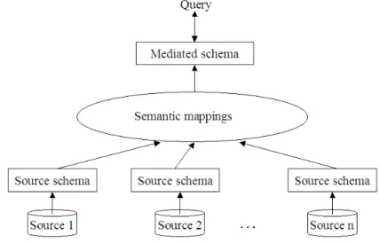
Most data integration systems employ a mediated schema, which is also known as a global schema. This is an approach where the entry of a data integration system is a set of data sources that are represented by their schemas (also known as local schemas). The integrated view is a global unification of the data coming from the multiple and heterogeneous sources in the system. This view, or uniform query interface, is built on the mediated schema. The mediated schema is purely logical and virtual in the sense that it is used to process queries but not to store data. The data remain in their data sources. To link the contents of data sources to the elements of the mediated schema, the data integration system employs a set of translation rules called schema mappings. The purpose of mappings is to capture structural as well as terminological connections between the local and the mediated schemas. Given a query from a user, the system employs a set of semantic connections between the mediated schema and local schemas of data sources to translate the user query to queries on data sources, then combine and return the results to the user. Figure 2.2 shows the general architecture of a data integration system based on mediated schema.
Figure 2.2: Architecture of a data integration system based on mediated schema
a wide range of autonomous and heterogeneous data sources by exploiting the semantic relationships between different source schemas, some challenges of this approach are:
• Design of a mediated schema must be done carefully and globally;
• Data sources cannot change considerably, otherwise they could violate the mappings to the mediated schema;
• Conceptual notions can only be added to the mediated schema by the central administrator.
2.1.3
Procedural and Declarative Approach
There are two principle approaches to data integration, namely the procedural and the declarative approach.
In the procedural approach, data is integrated in a ad-hoc manner according to a set of predefined requirements of information. In this case, the fundamental problem is how to design software modules so that they access to appropriate sources to fulfil the predefined requirements of information. Some data integration projects following this approach are TSIMMIS [55] and Squirrel [33, 55, 89]. They do not require an explicit notion of integrated schemas, and are based on two types of software components:
• wrappers wrap sources;
• mediators obtain information from one or more wrappers or other mediators,
refine this information through integration and conflict resolution of infor-mation coming from different sources, and provides inforinfor-mation output to the user or to other mediators.
The basic idea is to have a mediator for all types of query required by the user. Generally, there is no constraint on the consistency of the results retrieved from different mediators. For every two data sources to be integrated, a manuscript or a transformation program should be written and maintained. The latter is the toughest problem, because if a schema changes, the change must be detected and all the transformation manuscripts taking account of this schema, its source and its target must be updated. This requires a lot of maintenance work. Moreover, it is easy to forget several changes if there are so many of them. This problem becomes
2.2 CONCEPTUAL MODELING AND REASONING ADVANTAGES 13
even harder when many such transformations exist in an enterprise. Therefore, this type of ad-hoc integration is not scalable.
The major part of the current work on data integration adopts the declarative approach for the problem. The goal of this approach is:
• to model the data in a source by an appropriate language;
• to build a unified representation of data;
• to refer to such a representation in querying the integration system; and
• to derive query answers through the appropriate mechanisms accessing sources.
Therefore, this approach assumes that a system of data integration is character-ized by explicitly giving users a virtual, reconciled, and unified view of data in a knowledge representation formalism. The latter is often called the common data
model of the system. The virtual concepts in the view are mapped to the concrete
data sources, where the actual data reside, by explicit mapping assertions. Thus, the user formulates his or her question in terms of the common data model, and the system decides how to exploit the mappings to reformulate the question in terms of the language appropriate to data sources.
The declarative approach provides a crucial advantage over the procedural one:
• Although building a unified representation may be costly, it allows us to maintain a consistent unified view of the information sources;
• This view represents a reusable component of a data integration system;
• By this approach, data integration systems can be built by using conceptual modeling and reasoning techniques whose advantages will be shown in the next section.
2.2
Conceptual Modeling and Reasoning
Advan-tages
Conceptual modeling (CM) deals with the question on how to describe in a declarative and reusable way the domain information of an application, its relevant
vocabulary, and how to constrain the use of data, by understanding what can be drawn from it. CM provides the best vehicle for a common understanding among partners with different technical and application backgrounds. It facilitates information exchange over the Internet and within heterogeneous data sources. Actually, CM of an application domain and reasoning support over conceptual models have become critical for the design and maintenance of Semantic Web services requiring data integration.
The role and importance of CM in traditional architectures for information man-agement systems is well known and tools for CM are commonly used to drive system design [88]. We can give a list of advantages of CM regarding the design and the operation of an integration system as follows.
• Declarative and system independent approach. In general terms, one can say
that CM is the obvious mean for pursuing a declarative approach to Data Integration. As a consequence, all the advantages deriving from making various aspects of the system explicit are obtained. The CM provides a system independent specification of the relationships within sources.
• High level of semantics in user interface. One of the most tangible effects of
CM has been to break the barrier between user and system by providing a higher level of semantics in the design and user interface as well. Conceptual models are often expressed in graphic form and even expressed in closed-natural language. This is the key factor in presenting the overall information scenario in user interfaces.
• Incremental approach. With CM, the overall design can be regarded as
an incremental process of understanding and representing the relationships among data in sources. One can therefore incrementally add new sources into the integration system.
• Mappings. While in the procedural approach, the information about the
relationships among sources is hard-wired in the mediators, in a declarative approach it can be made explicit. The importance of this clearly emerges when information about data is widespread in separate sources that are of-ten difficult to access and not necessarily conforming to common standards. CM for Data Integration can thus provide a common ground for the overall relationships and can be seen as a formal specification explicit for media-tor design. By making the representation explicit, we gain the re-usability of the acquired knowledge, which is not achieved within a procedural approach. This explicit representation facilitates the mappings that can be done not
2.3 CONCEPTUAL DATA MODELING 15
only manually from experts because CM language is understandable for hu-mans, but also semi-automatically because experts can verify them.
Another set of advantages that one can obtain from the introduction of CM into data integration is related to the ability of reasoning over conceptual models. For example, one can use reasoning to check a conceptual representation (i.e. a model) for inconsistencies and redundancies; to maintain the system in response to changes in the information needs; to improve the overall performance of the system, etc. Essentially, if we take an Artificial Intelligence (AI) point of view, we can consider a whole integration system, constituted by an integrated view (with constraints), data sources, and mappings, as a knowledge base. In such a knowledge base, knowledge about specific data items (i.e. extensional knowledge) and knowledge about how the information of interest is organized (i.e. intensional knowledge) are clearly separated: extensional knowledge is constituted by the data sources, while intensional knowledge is formed by the integrated view and the mappings. Under this view, computing certain answers essentially corresponds to some reasoning activities or in other words, to some logical inference. The certain answers are those data that are logically implied by the data present in the sources and the information on the view and mapping.
All the advantages outlined above can be obtained by having the appropriate mod-eling methodologies and modmod-eling languages for representing conceptual model. A number of conceptual modeling languages have emerged as de-facto standard today, both in Database and Semantic Web technologies, such as ER, UML, ORM for the structured data models (e.g. relational database schemas), XML, RDF(S), DAML+OIL and OWL for the web semi-structured data model. However, many such languages do not have formal semantics based on logic, or reasoners built upon them to support the designer as well as the user. In Section 2.3, we will study some database conceptual modeling which are most popular today. Semantic Web technologies will be introduced in Chapter 3.
2.3
Conceptual Data Modeling
Given that most data sources are databases, specifically relational databases, we focus in this section on different conceptual data modelings, which are at the basis of the data integration framework. Conceptual data models describe the structure of the whole database for a community of users. They were developed to provide a high-level abstraction for modeling data, allowing database designers to
think of data in ways that correlate more directly to how data arise in the world. To capture the meaning of an application domain as perceived by its developers, conceptual models hide the physical storage structures and provide models that are more understandable to human. Database schemas could first be designed in a high-level semantic model and then translated into one of the traditional models for ultimate implementation. Capturing more semantics at the schema level allows the designer to declaratively represent relevant knowledge about the application. It follows that sophisticated types of constraints can be asserted in the schema, rather than embedding them in methods. Besides, it implies more possibilities to reason over the content of the database. Such reasoning can be exploited for deriving useful information for the solution of new problems posed by data integration (e.g. schema comparison and integration [35]). Thus, integrating semantics of data sources should be from conceptual models of these sources rather than from their logical or physical models. Before discussing the most popular conceptual data models, let us have a look at these three model levels in relational database design.
2.3.1
Categories of Data Models
The first step in meeting the communication challenge is to recognize that each database appears in different views, or data models. Each model is important and serves its own purpose, but not all are useful or even meaningful to everyone who participates in the design process.
The physical model. It is a view that is restricted to a specific relational database and to the physical implementation of that database. At this level, im-plementation details such as data types (e.g. “VARCHAR(5)”) or creation syntax (e.g. vendor specific SQL dialects) are shown. In more simple terms, a physical model is the code of the Data Definition Language (DDL, often, in SQL). In this language, many types of constraints can be defined, either via columns of table, or using more complex techniques such as the use of assertions or triggers. How-ever, for the user and performance requirement, physical models usually contain redundant data or information. For example, in physical models performance and convenience factors may cause new or altered indexes need to be created to speed up the query time; new other interfaces (e.g. views, stored procedures or addi-tional methods) may be added. Figure 2.3 is an example of a simple database schema described in a physical model. Since end users, clients, and most project managers are usually not steeped in such typical database terminology such as clustered indexes and foreign keys, the physical model is not an effective means of communication outside the realm of designers and programmers.
2.3 CONCEPTUAL DATA MODELING 17
CREATE TABLE Dept_Mgr(
dno INTEGER,
ssn CHAR(11) NOT NULL,
fromDate DATE, toDate DATE,
PRIMARY KEY (ssn, fromDate),
FOREIGN KEY (dno) REFERENCES Departement, FOREIGN KEY (ssn) REFERENCES Employes,
ON DELETE NO ACTION);
Figure 2.3: A simple schema in physical model
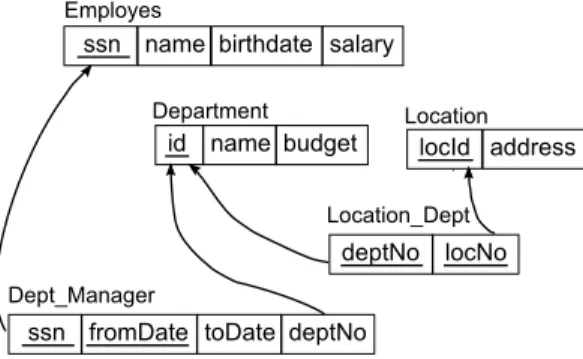
The logical model. Logical models serve as the basis for the creation of physical models. Logical models are biased towards the solution of the problem (designing). They need to specify technical details and so often use non-natural or machine lan-guage. However, logical models may not always correspond to physical models. In logical level, normalization [47] occurs while denormalization may occur in physi-cal level because of user or performance requirements. Therefore, logiphysi-cal model is often transformed into physical model by applying several simple modifications. The logical model is portrayed in the tabular form of relational model and shows the logical relationships between tables. The relational model [47] represents the database as a collection of tables of values, where each row represents a collection of related data values. The table name and column names are used to help in interpreting the meaning of the values in each row. All values in a column are of the same data type. In the formal relational model terminology, a row is called a tuple, a column header is called an attribute, a table is called a relation. Each relation is given a subset of attributes which is called a primary key to uniquely identify each tuple. A relation schema is made up of the relation name and a list of attributes. A relational database schema is a set of relation schemas and a set of integrity constraints such as the primary key constraint, the foreign key constraint, etc. The foreign key states that a tuple in one relation that refers to another relation must refer to an existing tuple in that relation. The foreign key is used to maintain the consistency among tuples of the two relations. Figure 2.4 shows an example of a relational database schema, where the underlined attributes make up the primary key; the attribute deptNo of Location Dept is a foreign key that gives the department number for its location and thus its value in every Location Dept tuple must match the id value of some tuple in the Department relation.
The limitation of relational models is that the meaning of a relation is entirely defined by the set of tuples that correspond to the relation. This means the meaning of a relation is not self-contained. The relation name and attribute names
have no formal meaning. In the relational model, there are no explicit relationships between different relations. These relationships in relational database schemas must be retrieved using queries on the database and some additional knowledge (e.g. a set of integrity constraints) that is not contained in the relational model.
Figure 2.4: An example of the database schema in the logical model
The conceptual model. Conceptual modeling provides richer data structuring capabilities for DB applications. A modeling method comprises a language and also a procedure for using the language to construct models. The language may be graphic (i.e. diagrams) and/or textual. In contrast to logical and physical models which specify underlying database structures to be used for implementation, con-ceptual models portray applications by using terms and concepts familiar to the application users. Conceptual models are then (automatically) translated (by the tool) into the corresponding logical schemas for the target Database Management System (DBMS).
We can use the following criteria [66] as a useful basis for evaluating conceptual modeling methods: expressibility, clarity, semantic stability, validation mecha-nisms and formal foundation. The expressibility of a language is a measure of what it can be used to say. Ideally, a conceptual language should be able to model all conceptually relevant details about the application domain. The clarity of a language is a measure of how easy it is to understand and use. Semantic stability is a measure of how well models or queries expressed in the language retain their original intent in the face of changes to the application. The more changes one is forced to make to a model or query to cope with an application change, the less stable it is. Validation mechanisms are ways in which domain experts can check whether the model matches the application. A formal foundation ensures mod-els are unambiguous and executable (e.g. to automate the storage, verification, transformation and simulation of models).
Entity-2.3 CONCEPTUAL DATA MODELING 19
Relationship, Unified Modeling Language and Object Role Modeling. We will investigate these mechanisms with regard to the above criteria in the next sections.
2.3.2
Entity-Relationship Model
One of the most widespread conceptual models becoming a standard and extensively used in the design phase of applications is the Entity-Relationship (ER) model [37]. In the ER model, the domain of interest is modeled by means of an ER schema. The basic elements of the ER schema are entities, relationships, and
attributes. An entity denotes a set of objects that have common properties. Such
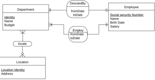
objects are called the instances of the entity. Elementary properties are modeled through attributes, whose values belong to a predefined domain such as String, Boolean. For example, an EMPLOYES entity may be described by its attributes: EMPLOYES’s name, birthdate, salary (cf. Figure 2.5). Properties of that are due to relations to other entities are modeled through the participation (total or partial) of their entity in relationships. A relationship denotes a set of tuples each of which represents a combination of instances of the entities that participate in the relationship. Since each entity can participate in a relationship more than once, the notion of ER-role is introduced, which represents such a participation and to which a unique name is assigned. The arity of a relationship is the number of its ER-roles. Cardinality constraints can be attached to an ER-role in order to restrict the number of times each instance of an entity is allowed to participate via that ER-role. Such constraints can be used to specify both existence dependencies and functionality of relations. They are often used in a restricted form, where the minimum cardinality is either 0 or 1 and the maximum cardinality is either 1 or ∞. Additionally, so called is − a relations are used to represent inclusion assertions between entities, and therefore the inheritance of properties from a more general entity to a more specific one. An important constraint is the key constraint on attributes. The attributes whose values are distinct for entity instances are called key attributes of that entity. For example, the social security number (ssn) attribute is a key of the EMPLOYES entity because no two employees are allowed to have the same ssn. The ER model uses diagram notations to describe ER schemas (Figure 2.5 is an example). In the ER diagram, the key attributes are indicated by the underlines.
The ER model is common in use because of the correspondence with the relational model, and the known translations from ER diagrams to relational models [47]. However, while in ER modeling, entities are explicitly specified and have a mean-ing, they only survive as meaningless names in the relational model (i.e. relation names). Furthermore, the relationships explicitly expressed in the ER model, are
DirectedBy fromDate toDate Department Identity Name Budget Employee Social security Number Name Birth Date Salary locate Location Location Identity Address Employ fromDate toDate
Figure 2.5: An example of the ER schema
hidden in the relational model.
Even though the ER model seems relatively simple (in the simple case just con-sisting of entities and relations), ER models can become quite complex, even for relatively simple domains [128]. Besides, ER modeling lacks the formal and real-world semantics. Reasoning on the ER schema has therefore been objectives of several works [31].
2.3.3
UML Class Diagram
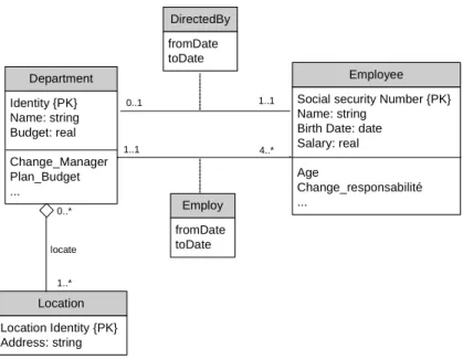
The Unified Modeling Language (UML) [104] has become widely used for soft-ware and database modeling. UML data modeling provides more expressive power in database schema definition. Indeed, several modeling constructs of UML data models are borrowed from the research on semantic data modeling and semantic networks in Artificial Intelligence (AI). For modeling notation, UML uses class diagrams to which constraints in a textual language may be added. Essentially, class diagrams provide an extended ER notation. Figure 2.6 shows how the ER schema of Figure 2.5 can be displayed using UML notation.
UML class diagrams allow for modeling, in a declarative way, the static structure of an application domain, in terms of classes and relations between them. A
class denotes a set of objects with common features, like entity in ER modeling.
A class is graphicly rendered as a rectangle divided into three parts (see, e.g., Figure 2.6). The first part contains the name of the class, which has to be unique
2.3 CONCEPTUAL DATA MODELING 21 Department Identity {PK} Name: string Budget: real Change_Manager Plan_Budget ... 0..1 1..1 Location Location Identity {PK} Address: string locate 0..* 1..* Employee Social security Number {PK} Name: string
Birth Date: date Salary: real Age Change_responsabilité ... DirectedBy fromDate toDate 1..1 Employ fromDate toDate 4..*
Figure 2.6: UML diagram of the example in Figure 2.5
in the whole diagram. Two other optional parts contain the attributes, like ER modeling, and the operations of the class, i.e. the operations associated to the objects of the class. An attribute a of type T for a class C associates to each instance of C a set of instances of T. Attributes are unique within a class, but two classes may have two attributes with the same name, possibly of different types. An association in UML is a relation between the instances of two or more classes. Therefore, associations can be bi-, thre- or n-ary. An association class describes the properties of an association, such as attributes, operations, etc. A particular kind of binary associations are aggregations, which denotes a part-whole relationship, i.e., a relationship that specifies that each instance of a parent class (the containing class) contains a set of instances of a child class (the contained class). In UML one can use a generalization between a parent class and a child class to specify that each instance of the child class is also an instance of the parent class (like is-a relations in ER modeling). Hence, the instances of the child class inherit the properties of the parent class, and satisfy additional properties that in general do not hold for the parent class. Several generalizations can be grouped together to form a class hierarchy.
UML allows cardinality constraints on both attributes and associations. Disjoint-ness and covering constraints are in practice the most commonly used constraints in UML class diagrams. Nevertheless, some useful representation mechanisms are not considered in UML schemas such as subsetting of attributes, inverse of attributes,
union and complement of classes, mainly because it is commonly accepted that part of the semantics of the application can be represented within methods. UML allows for other forms of constraints such as specifying class identifiers, functional dependencies for associations, etc., generally through the use of OCL (Object Con-straint Language) [113], a form of conCon-straint expressible in First-order logic (FOL) [52]. However, unrestricted use of OCL constraints makes reasoning on a class diagram undecidable, since it amounts to full FOL reasoning. Besides, the use of UML in industrial-scale software applications brings about class diagrams that are large and complex to design, analyze, and maintain. The expressiveness of the UML constructs may lead to implicit consequences that can go undetected by the designer in complex diagrams, and cause various forms of inconsistencies or redundancies in the diagram itself. This may result in a degradation of the quality of the design and/or increased development times and costs. Several works [15, 53, 49, 70] have proposed to describe UML class diagrams using various formal kinds in order to reason on UML class diagrams, and formally prove properties of interest through inference, and hence help the designer in understanding the hidden implications of his choices when building a class diagram.
2.3.4
Object Role Modeling
Object-role modeling (ORM) [68] is a conceptual modeling method for de-signing and querying data models. Typically, a modeler develops a data model by interacting with others who are collectively familiar with the application. These subject matter experts need not have technical modeling skills. Therefore, reli-able communication occurs by discussing the application at a conceptual level, using natural language and analyzing the information in simple units. ORM is specifically designed to improve this kind of communication.
Originally, ORM is a successor of NIAM (Natural language Information Analysis Method) [139] that was developed in the early 70’s to be a stepwise methodology arriving at “semantics” of a business application’s data based on natural language communication. Relational terms such as tables, columns, and keys do not exist in ORM because they are abstractions used for describing things stored in a re-lational database. Actually, Object Role Modeling got its name because it views the application world as a set of objects (entities or values) that plays roles (parts in relationships). ORM sometimes can be called as fact-based modeling because it verbalizes the relevant data as elementary facts. These facts cannot be split into smaller facts without losing information. The terms used in ORM have a direct relevance to concepts in the real world. Thus, this view of the world lets you describe the data in everyday terms rather than using an artificial language that
2.3 CONCEPTUAL DATA MODELING 23
is not effective in communicating and prone to being misunderstood. Value object
types (or simply Value types) and entity object types (or simply Entity types) are
distinguished by linguistic distinction. Value types correspond to utterable enti-ties (e.g. ‘Code’, ‘Firstname’) while entity types refer to “non-utterable” entienti-ties (e.g. ‘City’, ‘Person’). The relations between objects generates facts. ORM allows relationships with one role (for example, Person works), two, three, or as many roles as you like.
ORM has a rich language for expressing business rules, either graphicly or textually (i.e., the graphic form can be translated into pseudo natural language statements). In an ORM diagram, roles appear as boxes, connected by a line to their object type. A predicate is a named, contiguous sequence of role boxes. Since these boxes are set out in a line, fact types may be conveniently populated with tables holding multiple fact instances, one column for each role. This allows all fact types and constraints to be validated by verbalization as well as sample populations. Communication between modeler and domain expert takes place in a familiar language, backed up by population checks. It is easy to express virtually any style of static constraints upon the ORM diagram, such as mandatory, uniqueness (i.e. cardinality), subset, equality, exclusion, etc. These constraint types may also be combined. For example, an exclusion constraint may be combined with mandatory disjunction to specify that an object must either play role x or role y but not both. Suppose Table 2.1 includes data about departments employing employees. For simplicity, we assume that employees are identified by their names. The first row contains three elementary facts: the department identified “IT” employs the employee named “Hang DO”, the department identified “IT” employs from year “1996” and the department identified “IT” employs to year “2001”. The null value “?” indicates the absence of a fact to record a department MK’s end date. All the facts are elementary rather than compound. Therefore, null values do not appear in verbalization and eight facts can be extracted from Table 2.1.
Table 2.1: Some data of the department employment
Department Employee fromDate toDate
IT Hang DO 1996 2001
MK Marie CLAIRE 2000 ?
MK Hang DO 2002 2005
Although Table 2.1 includes eight fact instances, it has only three fact types: Department employs Employee, Department employs from Date and Department employs to Date. The facts in this table and the constraints on them can be modeled in ORM as in Figure 2.7. In this figure, we can see the population of the
facts corresponding to each fact type. (Note that the population is not part of the conceptual schema itself.)
Department (Id) Employee (Name) employsFrom employsTo Date IT 2001 MK 2003 IT 1996 MK 2000 MK 2002 employs/ is_employed_by IT Hang DO MK Marie CLAIRE MK Hang DO
Figure 2.7: Modeling the data of Table 2.1 in ORM
ORM has well-defined formal semantics. Actually, it has been fully formalized in FOL [131, 135, 132]. Conceptual query languages have also been designed for ORM like ConQuer [21]. ConQuer supports not only ORM queries but also the automatic translation from ORM to SQL queries. Furthermore, ORM includes a vast array of schema transformations as well as optimization heuristics to determine which transformations to use. For implementation, ORM schemas are usually mapped to relational database schemas, in which many fact types may be grouped into a single table (cf. Chapter 7). Actually, a correctly described ORM schema can be translated into a 5th normal form (5NF) relational database schema [13, 12]. A reverse engineering can also be provided to convert a relational database into an ORM schema [137].
2.3.5
Distinguish ORM from ER modeling and UML class
diagramming
Unlike ER modeling (or simply ER) and UML class diagramming (or simply UML), ORM treats all elementary facts as relationships, thus regarding decisions for grouping facts into structures (e.g. relation schemas, attribute-based entities, classes) as implementation concerns irrelevant to business semantics. The limits of ER and UML on conceptual data modeling with regard to the ORM method have been investigated in a series of works (e.g. [64]). In this section, we will review
2.3 CONCEPTUAL DATA MODELING 25
the main features that distinguish ORM from ER and UML. Note that UML is an extension of ER. Therefore, besides the limits of the extended part of UML, the limites of ER that we show here are also applied to UML.
Clarity limit. The semantics of ER and UML does not correspond to the real-world semantics of the domain of interest, but must accommodate itself to the ER and UML model. ER (UML) often requires to make arbitrary decisions about what an entity (class), a relationship (association), or an attribute is. Even ex-perienced modelers cannot think of data in ways that correlate to how data arise in the world. Consequently, the ER (UML) model is incomprehensible for users. Hence, although many users of tools for automating ER (UML) believe that they are creating a conceptual model, referring to the conceptual modeling criteria mentioned above, they are not. Actually, ER and UML can be classified to be at logical abstraction level [14]. To illustrate this, we will use examples that show the differences in the resulting schema in ER (UML) and ORM.
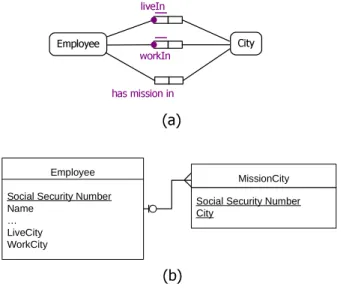
• Illogical attributes. Suppose adding to the schema given in Figure 2.7 two
fact types Employee lives in City and Employee works in City. In ORM, an Employee and a City are both conceptual objects (entities). You could tell someone that you (an Employee) works in Sophia-Antipolis (a City). But you would never try to explain to someone unfamiliar with database design that a City could ever be an attribute of an Employee. Let us say the attributes of an Employee may be the weight, height; but City could not logically an attribute of a person. Furthermore, City entity is converted to two attributes of the Employee (LiveCity) and (WorkCity) in an ER (UML) schema. There is no such thing as a LiveCity or a WorkCity in the real world. Accordingly, the real-world semantics of the domain of interest is missing in ER (UML) schema. Moreover, it is not relationally possible to have two attributes with the same name, such as City and City, in the same logical entity. You have to create attribute names that combine abbreviated semantic and domain information into a single attribute name. Figure 2.8 shows the two fact types that would be designed in ORM (a) and that would appear in an ER (UML) schema (b).
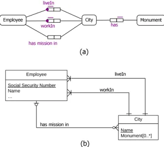
• Entities without real-world semantics. Suppose adding to the simple schema
given in Figure 2.8(a) a fact that an Employee has missions in multiple cities. Conceptually, this addition is simple: Add another fact type to the schema, reusing the Employee and City objects and naming the new role played as shown in an ORM schema in Figure 2.9(a). Note that the schema contains
only one Employee object and one City object. But in ER (UML), to add
Employee City
liveIn
worksin
(a) (b)
Employee Social security Number Name
… LiveCity WorkCity
Figure 2.8: An example illustrates the illogical attributes of an object in ER (UML) modeling
(or something similar) and their attributes (ssn of the Employee and City) to store all the Cities in which a given Employee has missions in (cf. Figure 2.9(b)). However, is there such a thing as a MissionCity entity? The an-swer is that this entity is not conceptual and was arbitrarily determined to accommodate the ER (UML) mechanisms.
Employee City liveIn workIn (a) (b) has mission in MissionCity Social Security Number City
Employee Social Security Number Name
… LiveCity WorkCity
Figure 2.9: An example illustrates the illogical entities in ER (UML) modeling
Attribute-based modeling limit. Attribute-based modeling in ER (UML) is also a source of many other problems that ORM does not encounter thanks to its attribute-free feature: