HAL Id: inria-00599694
https://hal.inria.fr/inria-00599694
Submitted on 10 Jun 2011HAL is a multi-disciplinary open access archive for the deposit and dissemination of sci-entific research documents, whether they are pub-lished or not. The documents may come from teaching and research institutions in France or abroad, or from public or private research centers.
L’archive ouverte pluridisciplinaire HAL, est destinée au dépôt et à la diffusion de documents scientifiques de niveau recherche, publiés ou non, émanant des établissements d’enseignement et de recherche français ou étrangers, des laboratoires publics ou privés.
Ontology Devoted to Exchanges in Mobile Robotics
Saadia Dhouib, Nicolas Du Lac, Jean-Loup Farges, Sébastien Gerard, Miniar
Hemaissia-Jeannin, Juan Lahera-Perez, Stéphane Millet, Bruno Patin, Serge
Stinckwich
To cite this version:
Saadia Dhouib, Nicolas Du Lac, Jean-Loup Farges, Sébastien Gerard, Miniar Hemaissia-Jeannin, et al.. Control Architecture Concepts and Properties of an Ontology Devoted to Exchanges in Mobile Robotics. 6th National Conference on Control Architectures of Robots, INRIA Grenoble Rhône-Alpes, May 2011, Grenoble, France. 24 p. �inria-00599694�
Control Architecture Concepts and Properties of an Ontology
Devoted to Exchanges in Mobile Robotics
Saadia Dhouib(1), Nicolas du Lac(2), Jean-Loup Farges(3), Sébastien Gerard(1), Miniar Hemaissia-Jeannin(4), Juan Lahera-Perez(5) , Stéphane Millet(6), Bruno Patin(6)
and Serge Stinckwich(7)
(1) CEA-LIST, (2) INTEMPORA, (3) ONERA (4) TRT, (5) INRIA, (6) DASSAULT AVIATION
(7) GREYC
Abstract
A specific ontology is proposed in the scope of the development of a platform devoted to exchanges between academics and industrials of the robotic domain. This paper presents the tools used for knowledge elicitation, the concepts and properties linked with control architecture, the use of the resulting ontology for description of some scenarios and the tracks for the development of a domain specific language grounded on the ontology. Knowledge elicitation is performed in web ontology language thanks to Protégé ontology editor. The ontology is structured as a set of modules organized around a kernel. Modules addressing systems, information, robot and mission include concepts and properties for control architecture description. The expressivity of the ontology is demonstrated describing architectures for a set of scenarios; urban robotic scenario, air-ground scenario, landmark search scenario and military unmanned aerial vehicles scenario. Finally some tracks for the use of the ontology for developing a domain specific language are given.
Keywords
Ontology ; Control ; Architecture ; Robot.
1
INTRODUCTION
An ontology is a formal representation of knowledge that describes a given domain [1]. It organize the knowledge as a set of concepts with relations between them.
Plateforme pour la Robotique Organisant les Transferts Entre Utilisateurs et Scientifiques (PROTEUS) is a research software platform under development [2] by several french academics and industrials partners. It aims at facilitating transfer of knowledge of the mobile robotic domain from the academic world toward the industrial one and problems from the industrial world toward the academic one. The PROTEUS specification propose the following use case:
• A first user of the platform provides a problem to the platform,
• A second user gets the problem from the platform and designs a solution for this problem,
• The second user provides the solution to the platform,
• The first user gets the solution from the platform.
This use case indicates that the second user has to understand the problem given by the first user and that the first user has to understand the solution given by the second user. Thus they have to share a common language; they have to agree to use a vocabulary in a way that is consistent with respect to a theory. Moreover, thanks to a computer science language consistent
with the theory, artificial agents that commit to the theory can be designed for the purpose of simulation or test on the field of the solution developed by the second user. For those reasons the development of a theory grounding a vocabulary is required for the PROTEUS platform. Candidates formalisms for specifying this theory are Unified Modelling Language (UML) and ontologies. Ontologies compliant with description logics are known to offer greater support for automated reasoning and cleaner solutions for defining complex relationships than UML. Thus the theory associated to the PROTEUS vocabulary is specified through an ontology. Moreover, simplifying the ontology into UML structural diagrams is an approach for the development of a Domain Specific Language (DSL), that may facilitate the exchanges between users, the configuration of simulation and the projection on actual robots.
2
STATE OF THE ART
Several ontologies have already been proposed in the context of robotics. There is a usually a distinction between ontologies designed to be used directly by robots during their reasoning and ontologies suitable to model the robotic domain in every aspect. Even if the intersection between these approaches is not empty, we are interested here mainly in the second category.
In the late nineties, two ontologies with concepts in French have been proposed from the study on test of decisional autonomy of robots: an robotics ontology and an environment ontology [3]. This robotics ontology is organized in five points of view: agent, component, flow, control and state. It is relevant for PROTEUS and its organization in points of view facilitate its presentation but the implementation of this organization through abstract classes may be a drawback for the development of a computer science language. The ontology includes some ternary relations that may be difficult to implement. In this ontology, the concept of state is defined in general terms that are applicable for continuous and discrete processes. However, the concept is used only in the discrete case. Each instance of the agent concept manages dynamics. This concept is a quite efficient way to specify a simulator to be generated. The hierarchical decomposition of the robot with components is an interesting feature with respect to the ability of generating simulations with different levels of abstraction. This decomposition could also be applied to functionalities and to states. Finally the robot components and the spatial objects could be specializations of a common concept.
Ontology based Component Oriented Architecture (OCOA) [4] is a robotic architecture based on behaviours and ontologies. The OCOA ontology describes a control architecture for a very specific component model. The generalisation of OCOA to a set of control architectures and component models could be very useful for PROTEUS.
The Multi-Layered Context Ontology Framework (MLCOF) [5] describes the context of a robot. MLCOF includes 6 Knowledge Layers (KLayer) : image, 1D geometry, 2D geometry, 3D geometry, object and space. The structure of the ontology of each KLayer is based on concepts, relations, functions of relations, hierarchies of concepts, relations of hierarchy and axioms. Each KLayer include a meta-ontology, an ontology and an ontology of instances. The meta-ontology describes general information about the entities to de modelled while the ontology describes specific entities. The main propose of MLCOF is to help robots in object identification tasks.
Ontology-based Multi-layered Robot Knowledge Framework (OMRKF) [6] is an extension of MLCOF. This robot centred description ontology is organized in knowledge boards with four knowledge levels: perception, model, context and activity. Each knowledge level is organized in three layers: high, intermediate and low levels. Each layer includes the same elements than MLCOF: meta-ontology, ontology and ontology of instances. OMRKF has been validated by an experiment with actual robots using Prolog to implement reasoning.
An ontology for robotic rescue with 230 classes, 245 attributes and 180 instances is presented in [8]. This ontology is specific for search and rescue missions.
RoSta1 (Robot Standards and Reference Architectures) is a Coordination Action (CA) funded under European Union’s Sixth Framework Programme (FP6) from January 2007 to February 2009. The objective of RoSta was to take initiative to defined formal standards in the context of advanced service robotics. In this context, they have defined a glossary and ontology2 for mobile manipulation and service robots.
The overview of the state of the art indicates that each ontology is devoted to a purpose. Thus a specific ontology is developed for PROTEUS. This ontology includes concepts and properties strongly linked with control architectures that are presented in this paper.
3
CONCEPTS AND PROPERTIES
3.1
Tools for Knowledge Elicitation
3.1.1
Web Ontology Language
The PROTEUS ontology is described using the Web Ontology Language (OWL). Three elements of OWL are extensively used for the PROTEUS ontology description: namespace, class and property.
A namespace is container that provide the context for the content of an OWL file. A namespace prefix can be used for modifying the meaning of the name of a class or a property in function of the context of the OWL file it belongs to. For instance a property
hasPhysicalCharacteristics, belonging to the kernel.owl file can be written
kernel:hasPhysicalCharacteristics.
A class encapsulates the meaning of a concept. Class hierarchies may be created by making one or more statements that a class is a subclass of another class. Classes may have instances.
A property describes a kind of association that is possible between classes. Property hierarchies may also be created by making one or more statements that a property is a subproperty of one or more other properties. For instance the has property, which is a generic composition property, can be specialized in hasPhysicalCharacteristics, which is a property that may apply only to physical objects.
3.1.2
Protégé
Protégé3 is an ontology editor that is compatible with OWL. The presentation of the ontology in this paper is illustrated by graphs generated with Protégé. Nodes of the graphs correspond to classes or instances and oriented arcs correspond to properties. Class hierarchies are symbolized on graphs by specific arcs with a isa label. Moreover an arc with an io label indicates that the upstream instance is an instance of the downstream class.
3.2
Ontology Structure
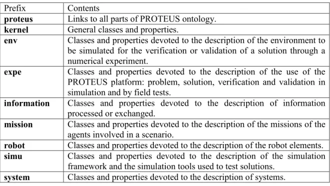
The ontology is organised in a modular way as a set of specialized modules build over a general purpose kernel. The kernel, as well as each module, corresponds to one specific OWL file and to one specific namespace. Moreover a specific PROTEUS file integrates the kernel and the modules. Namespace prefixes are systematically used for the names in the files. Table 1 indicates the namespace prefixes and the contents of corresponding OWL files.
1
http://www.robot-standards.eu/ 2
More information about this ontology are available in the deliverables D1.2 “Report on Requirement Analysis of Glossary/Ontology Standards”, D1.3 “Plan and Recommendations on Glossary/Ontology Standards” & D 1.4 “Example of modelling and design by using an ontology-based methodology”.
3
Prefix Contents
proteus Links to all parts of PROTEUS ontology.
kernel General classes and properties.
env Classes and properties devoted to the description of the environment to be simulated for the verification or validation of a solution through a numerical experiment.
expe Classes and properties devoted to the description of the use of the PROTEUS platform: problem, solution, verification and validation in simulation and by field tests.
information Classes and properties devoted to the description of information processed or exchanged.
mission Classes and properties devoted to the description of the missions of the agents involved in a scenario.
robot Classes and properties devoted to the description of the robot elements.
simu Classes and properties devoted to the description of the simulation framework and the simulation tools used to test solutions.
system Classes and properties devoted to the description of systems.
Table 1 : Namespace prefixes for PROTEUS ontology OWL files
The kernel and all the modules, except the env module, the expe module and the simu module, include knowledge about control architecture. Next sub-section includes the description of the system and kernel modules. Both are presented together because kernel is closely linked and dependent of system. Indeed, system represents the basis of the ontological architecture. Afterwards, each relevant module is introduced in successive sub-sections.
3.3
System and Kernel
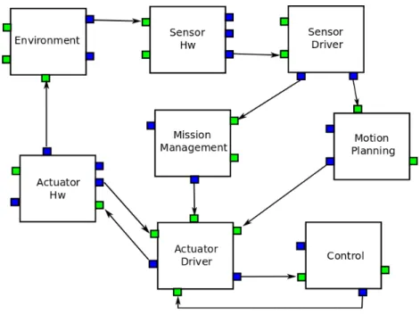
3.3.1 SystemThe present ontology follows a system-based or system-driven architecture. All the logical units or logical entities which achieve an interaction (either physical or logical interaction) with another entity in the ontology, are considered as a system. We can think of a system as a block which triggers interactions and is impacted by interactions coming from other systems, and which owns an input/output interface that we will call 'ports'. Thus, this logical entity is the basic communication unit of the PROTEUS ontology. Consequently, the control architecture of the final platform will rely and will be inspired somehow on this ontological basis. A clear evidence of this system-based ontology can be appreciated considering the development of the PROTEUS DSL; the language will have an important part of its architecture based on block entities with message passing between them by means of interconnected ports. This schema answers to the ontological basis of “system”. Hence, the final code generation and control architecture of the platform will be guided by the DSL and in turn by the ontology.
We can see a schematic example of the ontological idea of System, showing a possible graphical piece of the DSL in Figure 1.
Figure 1: System block diagram as it could be displayed by a graphical DSL
3.3.1.1 System Hierarchy
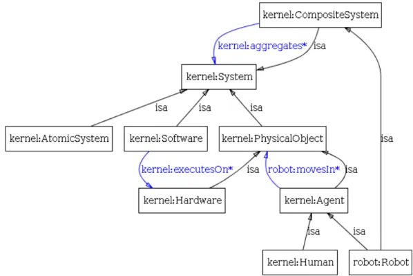
We can find several classifications of System, organized in a hierarchical way in the ontology. A first classification level is shown in Figure 2.
Figure 2: System's first level of classification
A system can be an aggregate of other subsystems (CompositeSystem) or an individual unit of interaction (AtomicSystem). It can be considered as a logical unit (Software) or as a physical entity (PhysicalObject). All of these aforementioned systems respond to a point of view about physical/logical components within the scenario (robotic hardware, robotic software, environment elements), hence it is a composition guided hierarchy. Nevertheless it is possible to add to this hierarchy a logical view of the functional part of the Robotic Platform; this is the RoboticManagementSystem entity. Finally, ControlStationSystem is an entity in the platform independent from a robotic system. However, this station communicates and controls a target robot of the specific scenario. There is a property hasEvolutionModel that links a System to one or several EvolutionModel. This feature can be used not only to describe the dynamics of any part of the control architecture but also the dynamics and capabilities of real components.
Figure 3 shows a part of this classification with some of the most important relationships mentioned above.
Figure 3: System classification and relationships
Some of the previous subclasses of System are worth explaining due to their meaning, subsequent classficiation and relationship with other entities:
CompositeSystem: As aforementioned, this is a composition of other subsystems. In this
classification, our ontology comprehends the following entities: Environment, Robot,
RoboticSubsystem. The latter is classified in turn in: ActuatorSystem, CommandableDeviceSystem, CommunicationSystem, PowerSystem and SensorSystem.
Except CommandableDeviceSystem which represents commandable units in the system hierarchy, all the other subclasses of systems are composed by both a driver and a hardware part. The ontology contains a constraint in order to impose the mixed Driver/Harware composition of a RoboticSystem.
PhysicalObject: It involves all the physical entities in the scenario. In the corresponding
subclassification it is possible to find Agent (Human and Robot), the different components of the Environment and Hardware. Hardware contains Clock, ActuatorHw (motorization, prehension or weapon hardware actuators), CommunicationHw, PowerHw and finally
SensorHw. As part of the sensor classification, the ontology embraces
EnvironmentParametersSensorHw, ImageSensorHw, LocalizationSensorHw, ObjectDetectionSensorHw, ObjectTrackingSensorHw.
Software: It makes reference to the logical component in a computational unit. It can be a
library, a framework, an object file or an Application (Driver or RoboticMiddleware in the case of the robotic platform). The drivers represent the software part of all the aforementioned hardware entities. Thus, parallely it is possible to find a driver for each one of the presented hardware components: ActuatorDriver, CommunicationDriver, PowerDriver, SensorDriver and the analogous subclassification for actuators and sensors that can be found
in the hardware as well.
Both parts, hardware and driver, make up the corresponding robotic subsystem for the robotic platform.
The link between Software and Hardware is also explicitly expressed by means of the relationship Software executesOn Hardware.
RoboticManagementSystem: This is the set of functional system entities of the robotic platform, i.e. the different main group of functions, which embraces different sets of algorithms, that will be used by the robotic platform in some specific scenarios. It does not involve the composition of the system as the previous classification, thus it is just another way to classify the systems without taking into account which software, hardware or physical objects compose it.
In this general functional set it is possible to find: ControlSystem, MissionManagementSystem, MotionPlanningSystem, PlatformManagementSystem and SecuritySystem.
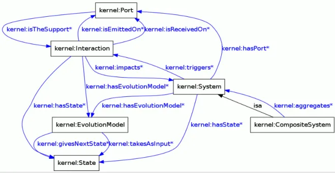
3.3.1.2 Interaction and dynamic aspects
Another important aspect to be described in this system-based architecture is the exchanges between systems. As shown in figure 4 System hasPort and Port isTheSupport of
Interaction. As aforementioned, Port is our entity to interface the input/output interaction
between systems. For emitting, System triggers Interaction that isEmittedOn Port. For the reception process, Interaction isReceivedOn Port and impacts System.
The System module of the ontology expands the notion of Interaction in order to embrace the relationships between the physical and logical components of the platform: Hardware and Software. Hence, it is considered SoftwareToSoftwareInteraction, DriverToPhysicDeviceInteraction and PhysicDeviceToDriverInteraction as a classification
of Interaction. Other interactions triggered by some systems are introduced in the classification; in this way Noise and Bias represent interactions which can impact on
SensorSystem or ActuatorSystem, for example. This hierarchy is shown in figure 5.
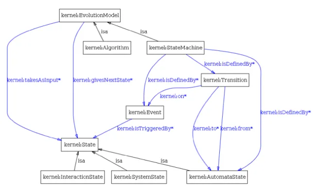
It is essential to describe not only the structure of the system architecture but also its dynamical aspects. The EvolutionModel class is the basis for the description of this dynamic. Not only System, but also Interaction hasEvolutionModel.
Two specific types of EvolutionModel (Algorithm and StateMachine) and the general schema of evolution are presented on figure 6. An Algorithm is an effective method for solving a problem expressed as a sequence of instructions. A StateMachine isDefinedBy
Transitions and Events and, of course, it relies in the entity State to carry out the evolution of
Figure 4: Interactions and dynamic aspects of a System
Figure 6: EvolutionModel.class
3.3.2 Information
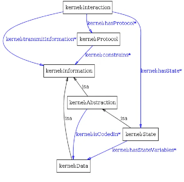
The Information class that is a central concept in PROTEUS ontology. As shown on figure 7, Information is directly and indirectly linked to Interaction. The direct link indicates that
Interaction transmitInformation. The indirect link indicates that Interaction hasProtocol
and that Protocol constrains Information.
Both Data and Abstraction are Information. Data is directly interpretable by a machine, for example boolean and bits are Data. Abstraction is not directly interpretable by a machine but provides some meaning that can be indirectly interpretable, for instance State is an
Abstraction meaning that the Information can be the input or the output of an EvolutionModel. It is important to note that Abstraction isCodedIn Data. Indeed despite the
fact that objectively speaking a control architecture only processes and transmits Data, the understanding and analysis of the architecture is grounded on Abstraction.
Figure 7: The Information class
3.4
Information
The main classes of information namespace that are relevant for architecture description are specializations of kernel:Data. Those classes, shown on figure 8 are:
• Collection contains a possibly modifiable set of kernel:Data with coherent types
and fitted with a data structure (indexation, ad hoc or natural order, father/child relation, etc).
• PhysicalData represents a mathematical algebraic object with an associated physical
unit.
• TimestampedData is any information combined with a timestamp that may
represent its creation date.
• ComposedData represents any aggregation of heterogenous kernel:Data with no
specific structure (in the computer science meaning) which can be consistently interpreted in robotics. Of course, this is not exhaustive. This class can be widely extended depending on application. See messages like defined in JAUS, FIPA, ADL...
• PrimitiveData is a type of kern:Data which corresponds to the primitives of the
standard computing interpretation: boolean, classical number representation (int, double, ...), character
Figure 8: Main relevant classes and properties of information
3.5
Robot
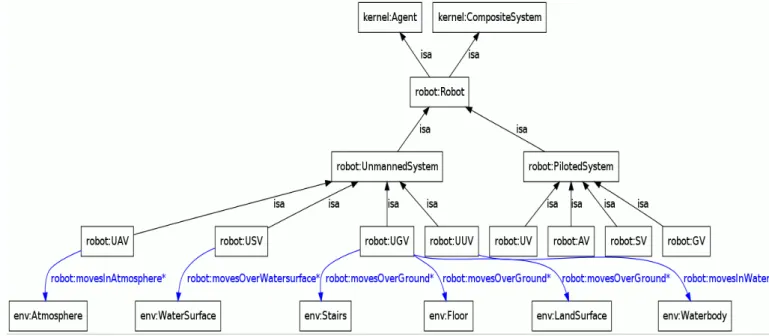
The module Robot of the ontology introduces the definition of the entity Robot as subclass of Agent and CompositeSystem. A constraint is imposed in the characterization of this entity:
Robot is an aggregation of some RoboticSystems (which are defined by the composition of a
software and a hardware part).
This module introduces a hierarchy based on unmanned/piloted property. It is possible to find aerial, water surface, ground and underwater vehicles in this classification for both unmanned and piloted robots. The “Robot” module is presented in figure 9.
Figure 9: Robot Module
3.6
Mission
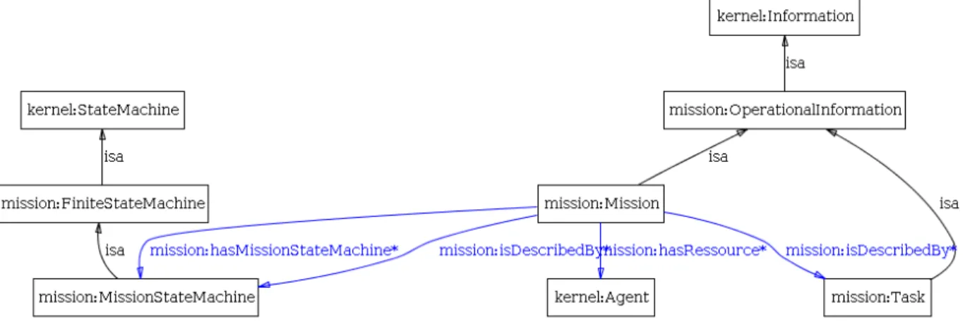
Figure 10 presents the main classes and properties of mission namespace.
The class OperationalInformation is a specialization of kernel:Information that is characterized by being related to operations. The ontology includes several specializations of
OperationalInformation. Among those specialisations Mission and Task are presented on
figure 10. Mission is a description of an operational mission that can be used by the
kernel:Agent performing it and that can be used for performance assessment. Task
corresponds to a task as defined in Hierarchical Task Networks.
The class FiniteStateMachine is a specialization of kernel:StateMachine that is characterized by having a finite number of kernel:AutomataState. The specialization
MissionStateMachine indicates that the FiniteStateMachine is the range of the property hasMissionStateMachine whose scope is Mission.
A Mission instance isDescribedBy its MissionStateMachine instances, its Constraint instances and its Task instances. The Workflow of the Mission isDescribedBy the same
MissionStateMachine instances.
Finally the hasRessource property allows the enumeration of kernel:Agent instances participating to a Mission instance.
Figure 10:Main classes and properties of mission
4
APPLICATION TO SCENARIOS
4.1
Scenarios
The validation of the PROTEUS platform is based on a set of robotic challenges. The problem associated with each challenge is provided to challengers through the PROTEUS platform and the challengers provide their solution to the problem through the PROTEUS platform. Each robotic challenge is a part of a more global scope corresponding to a scenario. For this reason, before developing a computer science language consistent with the ontology a set of scenarios are used for verifying it. The verification is based on four scenarios; three of them are directly issued for challenges and a fourth is issued from a different robotic domain.
The scenarios linked to challenges are:
• The urban scenario is an implementation of a robotized taxi service as a non segregated mode in the streets of a city. This scenario will conduct to a challenge on the Pavin test site in Clermont-Ferrand.
• The air ground scenario is an implementation of the use of unmanned aerial vehicles and unmanned ground vehicles for an area surveillance aiming at searching and tracking intruders. This scenario will conduct to a challenge on the military camp of Caylus.
• The landmark search scenario is an academic scenario for the pedagogic use of problem based learning in the institutions teaching robotics. This scenario will conduct to a challenge in the DGA site of Bourges.
The fourth scenario is a strike in the depth performed by a package of unmanned aerial combat vehicles. This military unmanned vehicle scenario is an implementation of the use of robotized aircraft for very dangerous war missions.
4.2
Urban robotic
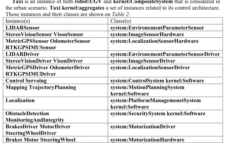
Taxi is an instance of both robot:UGV and kernel:CompositeSystem that is considered in
the urban scenario. Taxi kernel:aggregates a set of instances related to its control architecture. Those instances and their classes are shown on Table 2.
Instance(s) Classe(s)
LIDARSensor system:EnvironementParameterSensor StereoVisionSensor VisonSensor system:ImageSensorHardware
MetricGPSSensor OdometerSensor RTKGPSIMUSensor
system:LocalizationSensorHardware
LIDARDriver system:EnvironementParameterSensorDriver StereoVisionDriver VisonDriver system:ImageSensorDriver
MetricGPSDriver OdometerDriver RTKGPSIMUDriver
system:LocalizationSensorDriver
Control Servoing system:ControlSystem kernel:Software Mapping TrajectoryPlanning system:MotionPlanningSystem
kernel:Software Localisation system:PlatformManagemenetSystem kernel:Software ObstacleDetection MonitoringAndIntegrity system:SecuritySystem kernel:Software BrakesDriver MotorDriver SteeringWheelDriver system:MotorizationDriver
Brakes Motor SteeringWheel system:MotorizationHardware
Table 2. Instances related to control architecture and aggregated by Taxi
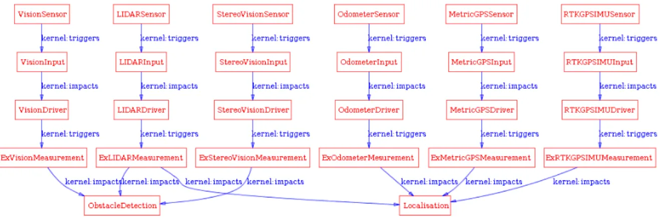
All instances belonging to Taxi are instances of classes specializing kernel:System. Thus those instances can kernel:triggers kernel:Interaction. Moreover kernel:Interaction can
kernel:impacts them. A set of instances of specializations of kernel:Interaction are used for
describing the exchanges. system:PhysicDeviceToDriverInteraction instances are: - LIDARInput - MetricGPSInput - OdometerInput - RTKGPSIMUInput - StereoVisionInput - VisionInput
system:SoftwareToSoftwareInteraction instances perform exchanges, abbreviated by Ex,
in the software part of the control architecture: - ExLIDARMeasurement - ExMetricGPSMeasurement - ExOdometerMeasurement - ExRTKGPSIMUMeasurement - ExStereoVisionMeasurement - ExVisionMeasurement - ExDetectedObstacle - ExEstimatedPosition - ExBeliefAboutEnvironement - ExTrajectory - ExCommands - ExBrakesCommand - ExMotorCommand
- ExSteeringWheelCommand
system:CommandOutput instances are:
- BrakesCommandOutput - MotorCommandOutput
- SteeringWheelCommandOutput
The kernel:triggers of the instances of specialisations of kernel:System and
kernel:impacts of the instances of specialisations of kernel:Interaction are set in order to
describe the control architecture of Taxi. The result is shown on figures 10, 11 and 12.
Figure 11: Sensing part of control architecture of Taxi
Figure 12:Functional part of control architecture of Taxi
Figure 13:Actuation part of control architecture of Taxi
In the urban scenario Taxi has to perform a mission which consists in picking and dropping passengers. The evolution of this mission is described by TaxiMissionEvolution instance of
mission:MissionStateMachine. TaxiMissionEvolution kernel:isDefinedBy seven
kernel:Transition instances and five kernel:AutomataState instances. Figure 13 illustrates
the use of the relations kernel:from and kernel:to for describing the evolution constraints.
Figure 14: Mission of Taxi
In order to be able to perform a mission, the previously described architecture has to be complemented with a mission management function. Figure 14 presents some aspects of this integration. TaxiMissionManager is an instance of system:MissionManagementSystem and
kernel:Software. It kernel:hasEvolutionModel TaxiMissionEvolution. ExDesiredDestination is an instance of system:SoftwareToSoftwareInteraction aiming at
giving a destination to TrajectoryPlanning. ExDestinationReachedSignal is an instance of and kernel:Event. The relation kernel:on of the kernel:Transition instances
StartPickingAfterEmpty and StartDroping are set to ExDestinationReachedSignal in order
Figure 15: Integration of a mission manager in the Taxi architecture
4.3
Air-Ground
RTrooper is an instance of both robot:UGV and kernel:CompositeSystem. Rmax is an
instance of both robot:UAV and kernel:CompositeSystem. Both are considered in the air ground scenario and kernel:aggregates a set of instances related to its control architecture. For example, as illustrated in figure 16, RTroper kernel:aggregates GPSSensorOfRTrooper that is an instance of system:LocalizationSensorHardware. The multi-robot architecture of the scenario is defined with RobotTeam that is an instance of kernel:CompositeSystem that
kernel:aggregates RTrooper and Rmax. RobotTeamMission is mission:Mission instance
that is performed by both robots. This is indicated by configuring the range of its
mission:hasRessource property with RTrooper and Rmax. RobotTeamMission mission:isDescribed by Surveillance and Detection that are instances of mission:Task,
indicating that some hierarchical planning has to be performed by the multi-robot architecture to fulfil its mission.
Figure 16:Multi-robot architecture of RobotTeam
4.4
Landmark Search
WifiBot is an instance of both robot:UGV and kernel:CompositeSystem. It kernel:aggregates a set of instances related to its control architecture. Among those instances:
- WheelMotor1, WheelMotor2, WheelMotor3 and WheelMotor4 are instances of system:MotorizationHardware.
- Odometer1, Odometer2, Odometer3, Odometer4, GPS, IMU and MagneticCompas are instances of system:LocalizationSensorHardware.
- Proxymeter1, Proxymeter2, Proxymeter3, Proxymeter4 and LaserRanging are
instances of system:ObjectDetectionSensorHardware.
- WifiLink is an instance of system:CommunicationHardware.
- WheelControl is an instance of system:Closed-Loop_ControlSystem and
kernel:Software.
- Localisation and Navigator are instances of system:PlatformManagemenetSystem
and kernel:Software.
- Servoing is an instance of system:ControlSystem and kernel:Software.
- ProximityMapping is an instance of system:SecuritySystem and kernel:Software. - GlobalPlanning is an instance of system:MissionManagementSystem and
kernel:Software.
- LocalMapping and PathPlanning are instances of system:MotionPlanningSystem
and kernel:Software.
The kernel:Software instances exchange information through an instance of
system:CommandOrder, ExCommands, and through a set of
system:SoftwareToSoftwareInteraction instances: ExEstimatedPosition, ExLocalMapInfo, ExLongTermObjective, ExPath, ExProximityMapInfo and ExShortTermTarget.
Figure 17 presents the description of the functional part of the WifiBot architecture with ontology instances. It is more complex than the functional part of the architecture of Taxi. It is interesting to observe the loop ExEstimatedPosition – LocalMapping – ExLocalMapInfo –
Localization that indicates a Simultaneous Localization And Mapping (SLAM) problematic
embedded in the landmark search scenario. An alternative architectural solution for WifiBoot could be to substitute LocalMapping and Localization by an kernel:AtomicSystem SLAM system.
Figure 17: Functional part of architecture of WifiBot
4.5
Military Unmanned Aerial Vehicles
In the following figure, we have an instance of kernel:CompositeSystem named FCAS, it aggregates of an instance of system:ControlStationSystem named GroundControlStation and two instances of robot:UAV named UAV7 and UAV8.
These 3 last instances are kernel:PhysicalObject which are part of an instance of
The GroundControlStation can interact with UAV7 and UAV8 using an instance of
kernel:Interaction named RobotControl.
Figure 18: High level system decomposition
In the following figure, we detail the different parts of UAV7 from the Hardware point of view. It has an instance of kernel:CompositeSystem based UcavPlatform. This platform aggregates two other kernel:CompositeSystem, one named UcavPayload, the other named
UcavEquipments.
The payload is composed of two system:WeaponHardware named BGL1000-1 and
BGL1000-2.
The defined pieces of equipment are a system:ObjectDetectionSensorHardware
RadarHarware, a system:MotorizationHardware, a system:CommunicationHardware
and a kernel:Hardware OnBoardComputer.
As can be seen below, the OnBoardComputer hosts several instances of
system:RoboticManagementSystem named: MissionManagementSystem, a
WeaponManagementSystem, a SensorManagementSystem and
NavigationManagementSystem. The OnBoardComputer interacts with the UcavPlatform7
using a kernel:Interaction named PlatformManagement.
Figure 20: Software hosted in computer of UAV7
In the following, we introduce an instance of mission:Mission named
UAVPackageMission. The resources for this mission are UAV7 and UAV8, this mission
defines a mission:MissionStateMachine which is used as a kernel:EvolutionModel by the
MissionManagementSystem of the UAVs. This MissionStateMachine has a
kernel:AutomataInitialState TakeOffPhase, a kernel:AutomataEndState LandingPhase
and several kernel:AutomataStates (DommesticPhase, FebaCrossingPhase, TacticalNavigationPhase, AttackPhase).
5
TOWARDS A DOMAIN SPECIFIC LANGUAGE
In the PROTEUS project, the usage of models in the context of the robotics domain is investigated into two forms: ontologies that have been presented in the previous sections and domain specific languages.
Coming from the Artificial Intelligence (AI) and Semantic Web (SW) circles, ontologies are used mainly to represent domains. The Model Driven Engineering (MDE) field gave birth to Domain Specific Languages (DSLs) to represent a particular technical domain. Several works have used ontologies for their semantic or structural synergy with DSLs. Those works are combining the ontologies with DSL at a meta-level to extend the coverage of a DSL [11] or to integrate a variability viewpoint straightforwardly in a DSML [12].
In the context of the PROTEUS project, the ontology is firstly used to represent the domain, i.e. inferring information from a Knowledge Base that complements with the DSL and then to develop the DSLs, i.e. as a representation of experts’ knowledge. The methodology we followed in PROTEUS is described in figure 17. We show the DSL design process that integrates the ontology. The design process consists in four steps:
1. The requirements of the DSL are gathered from both following sources: in the one hand from the ontology and in the other hand from the state-of-the-art on DSL for robotics systems.
2. Building the domain model of the DSL: The purpose of the domain model is to describe formally the concepts of the domain. The domain model is described by the means of one or more class diagrams, as well as in the form of textual descriptions.
3. Domain model verification: this step is intended to verify that the aforementioned domain model is covering all the requirements expressed in the first step. This step can lead to adding some concepts that have been integrated in the domain model of the DSL, and that are not belonging to the ontology.
4. UML/textual representation: An alternative for the specification of a DSL is the use of UML, which is a widely known modelling language that has a lot of support tools [13]. Another alternative is a textual representation of the DSL.
Figure 22: Methodology of the development of the PROTEUS DSL
The ontology is involved in the steps 1 and 2 of the DSL design process. Indeed, the first requirement of the DSL is to correspond to domain concepts defined in the ontology. The other requirements, coming from the ontology, are derived from this one. From the ontology, we extract all the concepts that are specific to the domain. Those concepts are then filtered to retain only the relevant ones for the DSL. On the other hand, if some concepts are missing in the ontology, they are added to the domain model of the DSL.
Ontology (OWL) Domain model (UML class diagram)
Concept Class
subClassOf Inheritance
Property Association, Attribute
Property:IsA Inheritance
Property:HasA Composition
Cardinality Multiplicity
Table 3. Mapping the ontology to the DSL domain model
The Table 3 shows the transition from the ontology, written in OWL DL language, to the DSL domain model specified as a UML class diagram. OMG also proposes the ODM (Ontology Definition Metamodel) which defines a set of QVT mappings from UML to OWL [14]. Only the automatic transformation from UML to OWL is implemented, the transformation from OWL to UML is not implemented yet. So we have not taken advantage of the ODM project to make the transition from OWL to UML.
6
CONCLUSION
The PROTEUS ontology devoted to the description of mobile robotic scenarios in view of their numerical simulation or test field is described using OWL. The kernel and the system,
information, mission and robot modules include classes and properties allowing control
architecture description. The main useful features provided by the ontology are:
• Basic concepts such as software, types of data, hardware, sensor, actuators and types of mobile robots,
• Hierarchical static system description suited as well for isolated robots than for groups of robots with a ground station,
• Dynamical system description grounded on interactions between systems and evolution models such as state machines,
• Decisional system description on the basis of tasks and mission.
None of those features is new. The contribution of the work is to gather them in a common framework understandable and sharable by a large majority of people involved in the development of control architecture of mobile robots. The use of the ontology for describing some aspects of several different scenario ranking from academic landmark search to military strike indicates that the ontology is able to gather information for different types of control architectures and is not devoted to a specific architectural approach. Finally the development of a DSL on the basis of the PROTEUS ontology open the way to automatic code generation for simulation and projection to a target robotic middleware.
However, the work on an ontology seem to be an endless work. Indeed:
• DSL developers are the first users of the ontology and their feedback may lead to some improvements.
• Then challenge providers and challengers, who will use the DSL to describe their problems and solutions, will probably have some feedback on the DSL. It is likely that this feedback will impact the ontology.
7
REFERENCES
[1] T. Gruber. Toward principles for the design of ontologies used for knowledge sharing. International Journal of Human-Computer Studies, 43(5-6):907–928, 1995.
[2] P. Martinet and B. Patin. PROTEUS: A platform to organize transfer inside french robotic community. In Proceedings of the 3rd National Conference on Control Architectures of Robots, CAR 2008, May 29-30 2008.
[3] P. Deplanques. Vers le test de l’autonomie des robots: une ontologie de la robotique. PhD thesis, Université de Montpellier 2, 1996.
[4] F. M. Casas and L. A. Garcìa. OCOA: An open, modular, ontology based autonomous robotic agent architectures. In D. Scott, editor, Artificial Intelligence: Methodology, Systems, and Applications, 10th International Conference, AIMSA 2002, volume 2443 of Lecture Notes in Computer Science, pages 173–182, 2002.
[5] W. Hwang, J. Park, H. Suh, H. Kim, and I. H. Suh. Ontology-based framework of robot context modeling and reasoning for object recognition. In L. Wang, L. Jiao, G. Shi, X. Li, and J. Liu, editors, Fuzzy Systems and Knowledge Discovery, Third International Conference, FSKD 2006, volume 4223 of Lectures Notes in Artificial Intelligence, pages 596–606. Springer-Verlag, 2006.
[6] I. H. Suh, G. H. Lim, W. Hwang, H. Suh, J.-H. Choi, and Y.-T. Park. Ontology-based multi-layered robot knowledge framework (OMRKF) for robot intelligence. In IEEE/RSJ International Conference on Intelligent Robots and Systems, pages 429–436. IEEE, 2007.
[7] J. Hallam and H. Bruyninckx. An ontology of robotics science. In H. Christensen, editor, European Robotics Symposium 2006, volume 22 of STAR (Springer Tracts in Advanced Robotics), pages 1–14. Springer-Verlag, 2006.
[8] C. Schlenoff and E. Messina. A robot ontology for urban search and rescue. In Proceedings of the 2005 ACM workshop on Research in knowledge representation for autonomous systems, KRAS 2005, pages 27–34. ACM, 2005.
[9] J. Bateman and S. Farrar. Modelling models of robot navigation using formal spatial ontology. In C. Freksa, M. Knauff, B. Krieg-Brückner, B. Nebel, and T. Barkowsky, editors, Spatial Cognition IV, volume 3343 of Lecture Notes in Artificial Intelligence, pages 366–389. Springer-Verlag, 2005.
[10] A. Chella, M. Cossentino, R. Pirrone, and A. Ruisi. Modeling ontologies for robotic environments. In Proceedings of the 14th international conference on Software engineering and knowledge engineering, SEKE 2002, pages 77–80. ACM, 2002.
[11] T. Walter and J. Ebert. Combining dsls and ontologies using metamodel integration. In W. Taha, editor, Proceedings of the IFIP TC 2 Working Conference on Domain-Specific Languages, number 5658 in Lecture Notes in Computer Science, pages 148–169. Springer-Verlag, 2009.
[12] B. Morin, G. Perrouin, P. Lahire, O. Barais, G. Vanwormhoudt, and J.-M. Jézéquel. Weaving variability into domain metamodels. In 12th International Conference on Model Driven Engineering Languages and Systems (MODELS 2009), volume 5795 of Lecture Notes in Computer Science, pages 690–705, Denver, Colorado, USA, Oct. 2009. Springer-Verlag.
[13] G. Giachetti, B. Martin, and O. Pastor. Using uml as a domain-specific modeling language: A proposal for automatic generation of uml profiles. In Advanced Information
Systems Engineering, volume 5565 of Lecture Notes in Computer Science, pages 110–124, 2009.
[14] IBM and Object Management Group and Sandpiper Software. Ontology Definition Metamodel (ODM). Available at: http://www.omg.org/spec/ODM/1.0/, 2009.