Publisher’s version / Version de l'éditeur:
Vous avez des questions? Nous pouvons vous aider. Pour communiquer directement avec un auteur, consultez la première page de la revue dans laquelle son article a été publié afin de trouver ses coordonnées. Si vous n’arrivez pas à les repérer, communiquez avec nous à PublicationsArchive-ArchivesPublications@nrc-cnrc.gc.ca.
Questions? Contact the NRC Publications Archive team at
PublicationsArchive-ArchivesPublications@nrc-cnrc.gc.ca. If you wish to email the authors directly, please see the first page of the publication for their contact information.
https://publications-cnrc.canada.ca/fra/droits
L’accès à ce site Web et l’utilisation de son contenu sont assujettis aux conditions présentées dans le site LISEZ CES CONDITIONS ATTENTIVEMENT AVANT D’UTILISER CE SITE WEB.
Paper (National Research Council of Canada. Institute for Research in
Construction), 1990
READ THESE TERMS AND CONDITIONS CAREFULLY BEFORE USING THIS WEBSITE. https://nrc-publications.canada.ca/eng/copyright
NRC Publications Archive Record / Notice des Archives des publications du CNRC :
https://nrc-publications.canada.ca/eng/view/object/?id=c100e6be-afd3-4c53-b679-e6745d28587a
https://publications-cnrc.canada.ca/fra/voir/objet/?id=c100e6be-afd3-4c53-b679-e6745d28587a
NRC Publications Archive
Archives des publications du CNRC
This publication could be one of several versions: author’s original, accepted manuscript or the publisher’s version. / La version de cette publication peut être l’une des suivantes : la version prépublication de l’auteur, la version acceptée du manuscrit ou la version de l’éditeur.
For the publisher’s version, please access the DOI link below./ Pour consulter la version de l’éditeur, utilisez le lien DOI ci-dessous.
https://doi.org/10.4224/40001431
Access and use of this website and the material on it are subject to the Terms and Conditions set forth at
Fire tower tests of stair pressurization systems with mechanical
venting of the fire floor
S e r
T H 1
National Research
Conseil national
n.
'
1
1 1
Council Canada
de recherches
Canada
1 9 9 0
BLDG.
Institute for
lnstitut de
-
Research in
recherche en
Construction
construction
Fire Tower Tests of Stair Pressurization
Systems with Mechanical Venting of the
Fire Floor
by G.T. Tamura
Reprints from
ASHRAE Transactions
1990, V. 96. Pt. 2
PP. 9
(IRC Paper No. 1691)
NRC
-
CIS77I R C
L I B R A R Y
APA
25
3 1
NRCC 32361
B I B L I O T H ~ Q U E
I R C
'CNRC-
ICImTOn a test& dans une tour d'experimentation incendie de
10
&ages, des
systemes d e pressurisation de cages d'escaliers selon divers schemas
d'utilisation des portes d'escaliers, dans des conditions de non-incendie et
d'incendie, et l'etage du feu &ant ventilk
A
l'aide d'un aspirateur. Les quatre
systemes en question comportaient les moyens suivants d'elimination de la
surpression
:
elimination au moyen de la porte de sortie, 6limination A l'aide
de registres barometriques, commande par retroaction utilisant une
derivation d e ventilateur, et commande par retroaction employant un
ventilateur
A
vitesse variable. Les essais ont rev616 que l'utilisation de l'un ou
I'autre des systemes d e pressurisation des escaliers et la ventilation
mecanique de l'btage du feu emp-aient
la
fum&
d'envahir la cage d'escalier
A
condition d'ouvrir quatre portes d'escaliers.
FIRE
TOWER TESTS OF STAIR PRESSURIZATION
SYSTEMS WITH MECHANICAL VENTING
OF THE FlRE FLOOR
G.T. Tamura, P.E.
Fellow ASHRAE
ABSTRACT
Stairshaft pressurization systems under various schedules of stair door operation, nonfirelfire conditions, and the fire floor vented with an exhaust fan were investigated in a 10-story experimental fire tower. The four stairshaft pressurization systems that were tested had overpressure relief features of exit door relief, barometric damper relief, feedback control with fan bypass, and feedback control with variable-speed fan. Tests have indicated that with
any
one of the stair pressurization systems on and with mechanical venting of the fire floor, the stairshat? was kept smoke free with four stair doors open.INTRODUCTION
For all tests, the door-opening sequence was the same
as the one used during the Phase 3 tests when the fire floor was vented with exterior wall vents (Tamura 1990b), i.e., stair doors on the exit floor, fire floor, one above the fire floor, and one of the upper floors opened sequentially. For all pressurization systems, the supply air was injected inside the stairshaft on floors 1, 3, 5, 7, and 10. The stairshaft pressurization systems were tested under the following schedules:
Nonfire Tests with Stairshaft Pressurization and Mechanical Venting of the Second Floor:
1. No doors ooen
2. Stair doors open on Floors 1 and 2 -
-
3. Stair doors open on Floors 1. 2. and 3An ASHRAE research project was undertaken to 4. Stair doors open on Floors 1; 2; 3, and 8. evaluate- the petformanc~
of
stair pressurizationsystems
withFire Teso Wirh Stairohan Pressurkation and MxhanicaI overpresJure control. The
Rrst
phaseot
the project involvedVenting (he Second Flmr:
a literature revim (Tamura 1989) and the second phase
lnvokred field evaluation
of
stairshaft pressurization systems 1. At a fire temperature of8 4 W
(450°C) and with the (Tarnura 1990a). exterlor wall vents on the secondflmr
closed (intended asThe third phass i n v o w evaluating the Peflormmce of a low-temperature fire), the a w e door-opening sequence
the stair pressurization systems in
a
$0-story experimental was follmed umjl a bacmma
the swr door opening onfire tower. The resuhsm repofled in a companion Paper the second floor was observed. The stair door opening on Famufa 1 m b h indicated that, in many cases, Smoke the fire floor was decreased until backflow was prevented
bacMIw was PrWeflQd when the fire fI00r Was vented to and the d m r angle at the point & no backflow
was
noted. the outdmrs by exterior wall vents. A series of tests were Exterior wall vents on the second floor were opened for therefom planned to mamine the performance of the some of the low-temperature fire tests to determine their7 H e m s
when mmblned with mechanical venting of the fire effect on air velocities at the stair door opening on the same floor. Tlle resuhs of the tests are reported here. The four floor.stair pressurization systems that were ~nvestigaed had 2. At a fire temperature of 1200°F
(650%)
and with the overpressure relief features of exkl door relief, barometric exterior wall vents open (intended as a high-temperaturedamper refief, feedback control with fan bypass, and fire), the above door-opening sequence was followed until
feedback control with variable-speed fan. a backflow at the stair door opening on the second floor
TEST PROCEDURE
was observed. The stair door was again gradually closed and the door angle at the point of no backflow was noted.All tests were conducted in a 10-story experimental fire
tower located near Ottawa, Ontario. The details of the Pressure differences across stair doors were measured
experimental fire t m r equipped with various overpressure with a diaphragm-t~ P magnetic reluctance pressure relief features mi described In a companion
paper
Varnura
transducer, and the supply air rates for stairshaft 1 ggob). A" exhauff fan having a of 1 9 . ~ ~ 1 d m pressurization were measured at the flow-measuring station. 0.50 in.af
water (9 rn31sax
125 Pa) and a variabie-spnd Temperatures were measured with chromel-alumel drive w r e located ontop
of the return air shaft roof lwei. thermocouples. The average air velocities at the stair door The rsturn air shaftwas
arranged
to serve as a smoke owning on the second floor during nonfire tests were exhaust shaft. All shutters. to the return air shaft wereclosed
measured by carrying out a 21-Point hot-wire ~~emOmeter except for the one on the second floor (fire floor), which traverse. They were averaged to obtain the average air served as an exhaust opening with an area of 5.25 ft2 (0.49 velocity. Smoke backfl0w during the fire tests wasm2). determined with smoke sticks at the stair door opening on
George T. Tamura is Senior Research Officer in the Building Performance Section of the Institute for Research in Constructlonl National Research Council Canada, Onawa
THIS PREPRINT IS FOR DISCUSSION PURPOSESONLY, FOR INCLUSION IN ASHRAE TRANSACTIONS 1990. V. 96. Pt. 2. Not to be re~rlntedln In part w~thout wr~nen permusson of the Amer~can Soc~ety of Heating. Refr~gerattng and AlrCond~tlmlng Engineers. Inc
.
1791 Tullle Circle- NE. Atlanta. GA 30329 Opln'Ons' flndlngs, conclus~ons. or recommendations expressed In thls paper are those of the author@) and do not necessarll~ reflect the vlewsOf ASHRAEthe second floor. Carbon dioxide concentrations in the tower were measured with nondlspersFre infrard gas anatyzers.
The t&s with mechanical venting
ot
the
second flmr and those with both mectlanicd veniing and stairshaftpressurization were conducted under summer conditions only,
RESULTS AND DISCUSSION
Mechanical Exhaust of the Fire Floor
Tests of the stairshaft pressurization systems have indicated that venting of the fire floor by opening the exterior wall vents on the second floor increased the air veloclies at
the stair door opening (Tamura 1990b). Relieving pressures on the second floor by means of mechanical venting
is
therefore expected to improve the performance of stair pressurization syaems.Tests wars conducted inajally to evaluate the pefformance of mechanical venting alone without
stair
pressurization. The results of tests are given in Tables l aand I b. The
S
6cond floor was exhausted at a fate of 10,500 d m (4.97 mIs).
With all stair doors closed, the pressure d#ersnce across the stair door on the second flmr was0.116 in. d water (29 Pa). When the stair door on the
smxnd floor was opened, the average air velocity at the stair dmr was
1M
fpm (0.54 d s ) . When the stair doors on floors 1, 2, 3, end 8 were opened, the average air vefocrty increased to480
fpm
(2.44 d s ) but then decreased to 340 fprn (1.73 mls) when the exterior wall vents on the second floor wereopened
as
well, to simulate broken windows.Tabla l b shows that with a low-temperature fire and outside wall
rents
closed, smoke backflow occurred when the stair doorson
Rmrs 2 and 3 were opened. R was prevented when the stair doof an the eighth floor wasalso
opened, but It recurred when the outside wall vents were opened. When the stair door on the fitst floor was
also
opened under thb condition, smoke backflow was prevented. When the fire tempersture was then increased toI24W (G'PC), smoke backftcw was marginal. For the last two cases, the corresponding average air velocrty for the nonfire condition was 340 Ipm (1.73 mls) and the pressure difference across the stair door opening was 0.014 in.
of
water (3.5 Pa).
PRESSURE DIFFERENCE ACROSS STAIR DOOR. Pa
AIRRATE-17 &i 0 A C.4 UEOW(ICAL#HAUST RATE
-
10500 cbn (407 d h ) W m.4
6 LMEH)-
STAIR OPEN2
5ONIFIDmmFLooR
n 0 A 0 1PRESSURE DIFFERENCE ACROSS STAIR DOOR. INCH OF WATER
TABLE 1
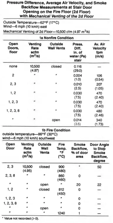
Pressure Difference, Average Air Velocity, and Smoke Backflow Measurements at Stair Door
Opening on the Fire Floor (2d Floor) with Mechanical Wbnting of the 2d Floor
Outside Temperature--62OF (17%) Wind-6 mph (10 kmh) east
Mechanical Venting of 2d Floor-10,500 cfm (4.97 m3/s) l a Nontire Condition
Open Venting Outslde Press. Av. Air Rate WaliVents Din.
-
uhn Velocity floor in. of fPm (m3/s) water (Pa) (mls) stalr none 2 2,3 1.2 1.2,3 1,2,3,8 closed 0.116 (29.0) 0.004 (1 .O) 0.010 (2.5) 0.030 (7.5) - lb Fire Conditlon outside temperat~re-46~F (30°C) wind--6 mph (10 kmh) southwestOpen Venting Outslde Fire Smoke Door A y l e Door Rate Wall Temp. Backflow, to Stop
scfm Vents OF $6 of door Smoke (m3/s) (*C) area Backflow, dearee 10,500 closed (4.95) I open closed open w
Value not recorded (> 0).
Tests have lndlcated that the average air velocity at the stair door increased as more stair docrrs were opened and decreased when the exterior wall vents were opened. This
effe-3 is opposite to that with stair pressurization; the
average air velocw decreased as stair doors were opened and increased when the exterior wall veMs were
opened.
It appearedthal
the two operationscan complemem
each other. Tests were conducted to investigate the performanceof the combined operation of stair pressurization with
rnechanlcal venting of the second floor. They were conducted lor the summer condition
only.
Mechanical Venting of the Second Floor and
Stairshaft Pressurization System with Exit Door
Relief
Figure 1 Pressure difference measurements with Nonflre Conditlon Pressure differences across the stair mechanical venting of second floor and s&& doors under nonfire conditions are shown in Figure 1. The pre~owization system with exit door relief, stairshaft wf3 pressurized with a supply air rate of 17.800
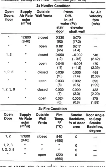
TABLE 2
Pressure Difference, Average Air Velocity, and Smoke
Backflow Measurements
ai
Stair Door Opening on the Fire Floor (2d Floor) of Staimhaft Pressurization System with ExitDoor Relief and Mechanical Venting of the 2d Floor Outside Temperature--73OF (23°C)
Wind-7.5 mph (12 kmh) south
Mechanical Venting of 2d Floor-10,500 cfrn (4.97 m3/s) 2a Nonflre Condition
Open Supply Outside Press. Av. Air Doors, Air Rate Wall Vents Dlff. Velocity
floor scfm in. of
(m3/s) water (Pa) (mk) fpm
stair elevator door shaft wall
1 17,800 closed 0.330 0.070
-
(8.40) (82) (17.2) I open 0.181 0.017-
(45) (4.4) 1, 2 closed 0.050 -0.002 516 (12) (-0.6) (2.62) open 0.045 -0.006 470 (11) (-15) (2.39) 1,2,3 closed 0.039 0.005 468 (10) (1.4) (2.38) open 0.033 0.002 392 (8) (05) (1.99) 1,2,3,8 " closed 0.030 0.009 433 (7) (2.3) (2.20) open 0.024 0.003 ,370 (6) (0.8) (1.W
2b Fire ConditionOpen Supply Outside Fire Smoke Door Angle Door Air Rate Wall Temp. Backflow, to Stop
scfm Venta O F %of door Smoke
(m3/s) (OC) area Backflow,
degree 1, 2 17,800 closed 840 0
-
(8.40) (450) 1,2,3 0-
1. 2, 3, 8 " 0-
open 1220 0-
rate of 10,500 cfm (4.97 m3/s). The pressure differences were much greater than those with the stairshaft pressurized and with no mechanical exhaust of the second floor (Tamura 1990). Except for floors 1 and 2, the pressure differences across all doors were about 0.10 in. of water (25 Pa) with stair doors open on floors 1, 2, 3, and 8. Those on floors 1 and 2 were 0.006 and 0.020 in. of water (0.5 and 5 Pa), respectively.
Table 2a gives the pressure difference and the average air velocity at the open stair door on the second floor during the door-opening test with the exterior wall vents on the second floor closed and open (simulating broken windows) and under nonfire conditions. With the exterior wall vents closed, the pressure differences across the open stair door on the second floor varied from 0.030 to 0.050 in. of water
f7
to 12 Pa); with them open, they varied from 0.024 to 0.045 in. of water (6 to 11 Pa). The average air velociies varied from 433 to 516 fpm (2.20 to 2.62 m/s) with the exterior wall vents closed as compared to 370 to 470 fpm (1.88 to 2.39 mls) with them open. These average air velocities are considsrably greater than those with stair pressurization systems alone.Fire Condition Table 2b gives the results of the fire tests. There was no smoke backflow at fire temperatures of 840°F (450°C) with the exterior wall vents closed or 1220°F
PRESSURE DIFFERENCE ACROSS STAIR WOR. Pa -25 STlRSHAFIswPLY AIR MTE
-
15,m dn 8 UECHAMCALDMAlsl ~E-10500da 7 (497 mlh) C rn o u r S l D E ~ P . 7 5 F p 4 ~ 1 I I WfND 6.0 mph (10 brim) EAST 1 I -0.1 0.0 0.1 0 2 0.3 0.4PRESSURE DIFFERENCE ACROSS STAIR DOOR, INCH OF WATER
ngum 2 Pressure difference measurements with mechanical venting of second floor and stair pressurization system with barometric damper relief, nonfire condition
(660°C) with the exterior wall vents open when doors on floors 1, 2, 3, and 8 were open. The minimum average air velocities during the nonfire tests that prevented smoke backflow were 392 fprn (1.99 mls) for the low-temperature fire with stair doors open on floors 1, 2, and 3 and the second floor wall vents closed and 370 fpm (1.88 mls) for the high-temperature fire with stair doors open on floors 1, 2, 3, and 8 and the second floor wall vents open.
Mechanical Venting of the Second ~ l o d / and
Stairshaft Pressurization System with Barometric
Damper Relief
Nonfire Condition Pressure differences ross the stair doors under nonfire conditions are shown in
?
igure 2. The second floor was exhausted at a rate of 10,500 cfm (4.97 m3/s). The supply air rate fo stairshaft pressurization was5
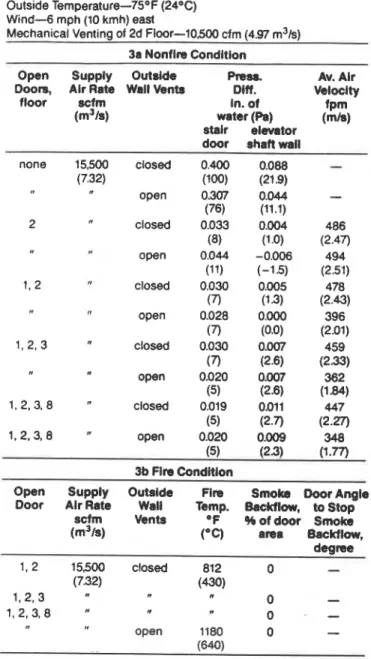
set at 15,500 cfm (7.32 m Is) to prevent the pressure difference across the stair door on the second floor from exceeding 0.40 in. of water (100 Pa) with all stair doors closed. Except for floors 1 and 2, the pressure differences across the doors were about 0.05 to 0.10 in. of water (12 to 25 Pa) when stair doors on floors 1, 2, 3, and 8 were opened. Those on floors 1 and 2 were about 0.010 and 0.015 in. of water (2 and 4 Pa), respectively. Because of the reduced supply air rate, these pressure differences were lower than those for the previous case for a stair pressurization system with exit door relief when the stair doors were opened (Tamura 1990).Table 3a gives the pressure differences and the average air velocities at the open stair door on the second floor during the door-opening test with the exterior wall vents on the second floor closed
and
open. The tests were conducted under nonfire conditions. With the exterior wall vents closed, the pressure differences across the open e i r door on the second floor varied from 0.019 to 0.033 In. of water (5 to 8 Pa); with them open, they varied from 0.020 to 0.044 in. of water (5 to 11 Pa). The average air velocities varied from 447 to 486 fpm (2.27 to 2.47 m/s) with the exterior wall vents closed as compared to 348 to 494 fpm (1.77 to 2.51 m/s) with them open. The above values are slightly lower than those for the previous case with exit door relief.Fire Condition Table 3b gives the results of the f~re tests. There was no smoke backflow at fire temperatures of 81 0°F (430°C) and 1 180°F (640°C) when doors on floors 1,
TABLE 3
Pressure Difference, Average Air Velocity, and Smoke Backflow Measurements at Stair Door Opening on the Fire Floor (2d Floor) of Stairshaft Pressurization System with
Barometric Damper Relief and Mechanlcal Yenting of the 2d Floor
Outside Temperature-7S°F (24"C) Wind--6 rnph (10 kmh) east
Mechanical Venting of 2d Floor-10,500 cfrn (4.97 m3/s)
3a Nonfire Condition
Open Supply Outside Press. Av. Air
Doors, Air Rate Wall Venta Olff. Velocity
floor scfm ln. of
(m3 is) water (Pa) (mk) fpm
stair elevator door shaft wall
-- none 15,500 closed 0.400 0.088
-
(7.32) (100) (21.9) open 0.307 0.044-
(76) (11.1) 2 closed 0.033 0.004 486 (8) (1.0) (2.47) open 0.044 -0.006 494 (11) (-15) (2.51) 1 , 2 closed 0.030 0.005 478 (7) (1.3) (2.43) n open 0.028 0.000 396 (7) (0.0) (2.01) 1, 2, 3 closed 0.030 0.007 459 (7) (2.6) (2.33) open 0.020 0.007 362 (5) (2.6) (1.84) 1,2,3,8 " Closed 0.019 0.011 447 (5) (2.7) (2.27) 1.2.3.8 " open 0.020 0.009 348 (5) (2.3) (1.77) 3b Flre ConditionOpen Supply Outside Fire Smoke Door Angk Door Alr Rate Wall Temp. Backflow, to Stop
scfm Vents O F %of door Smoke
(m3W (*C) area Backt~ow, d c g m 1, 2 15500 Closed 812 0
-
(7.32) (430) 1,2,3 n 0-
1,2,3,8 " " 0-
,
open 1180 0-
(640)2, 3, and 8 were open. The minimum average
air
velocities during the nonfire tests that prevented smoke backflow were 362 fprn (1.84 m/s) for the low-temperature fire with stair doors open on floors 1, 2, and 3 and the second floor wall vents open and 348 fprn (1.77 m/s) for the high-temperature fire with stair doors open on floors 1, 2, 3, and 8 and the second floor wall vents open.Mechanlcal Venting of the Second Floor and
Stairshaft Pressurlzatlon Systems with Fan Bypass
and with Variable-Speed Fan
Nonflre Condition Pressure differences across the stair doors under nonfire conditions are shown
in
Figure 3. The pressure difference across the stair door on the fifth floor was controlled at 0.130 in. of water (32 Pa). The pressure differences above the third floor remained at about this value for all door-opening tests. The pressure differences were about 0.005 to 0.030 in. of water (1 to 7 Pa) for the first floorPRESSURE DIFFERENCE ACROSS STAIR DOOR, Pa
LEGEND
'
'
STAlAOOORSWENON WRY
IM)lXl€O AJRR41E
PRESSURE DIFFERENCE ACROSS STAIR DOOR.
INCH OF WATER
figure 3 Pressure difference measurements with mechanical venting of second floor and stair pressurization system with fan bypass, nonfire condition
and 0.020 to 0.032 in. of water (5 to 8 Pa) for the second' floor.
Table 4a gives the pressure differences and the average air velocities at the open stair door on the second floor during the door-opening test with the exterior wall vents on
the
second
floor closed and open. The tests wereconducted under nonfire conditions. With the exterior wall vents closed, the pressure differences across the open stair door on the second floor varied from 0.035 to 0.058 ifl. of water (9 to 14 Pa); with them open, they varied from 0.034 to 0.053 in.
of
water (8 to 13 Pa). The average air velocities varied from 478 to 588 fprn (2.43 to 2.99 m/s) with the exterior wall vents closed as compared to 443 to 539 fprn (225 to 274 m/s) with them open. The values of pressure diierences and average air velocities are greater than those of exit door relief with mechanical venting.Fire Condttion Table 4b gives the results of the fire tests. There was no smoke backflow at fire temperatures of
8404
(450°C) and 1200°F (650°C) when doors on floors 1,2, 3, and 8 were opened. The minimum average air velocities during the nonfire tests that prevented smoke backflow were 478 fprn (2.43 m/s) for the low-temperature fire with stair d mopen on floors 1, 2, 3, and 8 and the second floor wall vents closed and 480 fprn (280 d s ) for the hlgh-temperature fire with stair doors open on floors 1, 2, 3, and 8 and the second floor wall vents open.
The results for the stair pressurization system with variable-speed drive fan are similar to those of fan bypass; they are given in Figure 4 and Tables 5a and 5b.
Smoke Concentration Patterns
In addition to pressure differences, C 0 2 concentrations were measured throughout the tower during fire tests. Concentrations of C02 as a surrogate indicator of smoke can be expressed
as a
percentage of the concentration in the bum area of the second floor. Froma
consideration ofsmoke
obscuration, an area is assumed to be reasonablysafe if it
is
not contaminated to an extent greater than 1% of thatIn
the vicln'qof
the burn area (McGuire et al. 1970).Table 6 gives the smoke concentration patterns caused by fire at steady-state conditions and without stair pressuriiation
or
mechanical venting. Under the summer condition, with the exlerior wall vents on the second floor open and a fire temperature of 840°F (450"C), the smoke concentrations exceeded the 1% level in the stairshaft, elevator shaft, service shaft, and floor spaces. TheTABLE 4
Pressure Difference, Average Air Velocity, and Smoke Backflow Measurements at Stair Door Opening on the Fire
floor (2d Floor) of Stairshaft Pressurization System with An Bypass and Mechanical Venting of the 2d Floor
Outside Temperature-73OF (23OC) Wind-5 mph (8 kmh) southwest
Mechanical Venting of 2d Floor-10,500 cfm (4.97 m3/s)
4a Nonflre Condition
Open Supply Outside Press. Av. Air
Doors, Alr Rate Wall Vents Diff. Veloclty
floor scfm In. of
(m3/s) water (Pa) fpm
stair elevator (mls) door shaft wall
none 1700 closed 0.248 0.052
-
(0.80) (62) (12.9) 1700 open 0.146 0.004-
(0.80) (36) (1.0) 2 14.160 Closed 0.058 -0.010 588 (6.68) (14) (-2.5) (2.99) 13.650 open 0.053 -0.011 539 (6.40) (13) (-2.7) (2.74) 1. 2 15,690 closed 0.045 -0.008 476 (7.40) (11) (-2.1) (2.42) 15.690 open 0.038 -0.008 443 (7.40) (91) (-1.9) (2.25) 1, 2, 3 17.430 closed 0.038 -0.002 484 (8.22) (9) (-0.4) (2.46) 17,050 open 0.031 -0.004 450 (8.05) (8) (-11) (2.26) 1, 2, 3. 8 24.700 closed 0.035 0.011 478 (1 1.66) (9) (2.7) (2.43) 24,420 open 0.034 0.012 480 (11 52) (8) (3.0) (2.45) 4b Fire ConditionOpen Supply Outside Fire Smoke Door Angle
Door Air Rate Wall Temp. Backflow, to Stop
sctm Vents 'F %of door Smoke
(m31s) (OC) area Backflow,
degree
2 14,480 closed 840 0
-
(6.98) (450)29,000 open 1200 0
-
(13.69) (650)concentrations in the stairshafts varied from 6% on the second floor to 9% on the tenth floor. When the stair door on the second floor was opened, the concentrations in the stairshaft increased greatly, from 70% on the second floor to 66% on the tenth floor.
Smoke concentrations with mechanical venting of the second floor and the second floor wall vents closed are given in Table 7. With all stair
doors
closed, smoke concentrations were zero everywhere except for the fire floor. When stair doors were opened on the first and secondfloors, smoke concentrations everywhere In the tower were well above the critical level except in the stairshaft at the first floor level; this was also the case, but with somewhat lower values, when the stair door on the third floor was also opened. Although smoke backflow was prevented at the open stair door on the second floor (Table lb), smoke spread from the elevator and setvice shafts into floor spaces
TABLE 5
Pressure Difference, Aveage Air Velocity, and Smoke Backflow Measurements at Stair Door Opening on the Fire
Floor (2d Floor) of Stairshaff Pressurization System with Variable-Speed A n and Mechanical
Venting of the 2d Floor
Outside Temperature--80°F (n°C) Wind-6 mph (10 kmh) south
Mechanical Venting of 2d Floor-10.500 cfm (4.97 m3/s)
Sa Nontire Condition
Open Supply Outside Press. Av. Air
Doors, Air Rate Wall Vents Dlff. Velocity
floor sctm in. of fPm
(m3/s) water (Pa) (m/S)
stair elevator door shaft wall
none 3150 closed 0.325 0.057
-
(1 .87) (81) (14.2) none 3150 open 0.183 0.007-
(1.87) (45) (1.8) 2 14.660 0.060 -0.008 624 (6.92) (15) (-2.1) (3.17) 14,660 open 0.058 -0.014 540 (6.92) (14) (-3.4) (2.75) 1, 2 15,830 closed 0.056 -0.005 504 (7.47) (14) (-1.3) (2.56) 15,830 open 0.042 -0.010 453 (7.471 (10) (-2.6) (2.30) 1, 2, 3 17,900 Closed 0.046 -0.002 484 (a451 (11) (-0.6) (2.46) 17,400 open 0.040 -0.008 464 (8.21) (10) (-1.9) (2.36) 1, 2.3. 8 24,900 closed 0.043 0.016 464 (11.75) (10) (4.1) (2.36) 25,000 open 0.038 0.012 433 (11 8) (9) (2.9) (2.20) Sb Fire ConditlonOpen Supply Cutside Fire smoke\ Door Angle
Door Air Rate Wail Temp. Backflow, to Stop
scfm Vents OF %of door Smoke
(m3/s) (OC) area Backflow,
dearee - - - 2 14.480 closed 812 0
-
(6.w (450) 1,2 16,900 (I I 0-
(8.00) 1,2.3 19.460 w 0-
(9.18) 1,2,3.8 24450 a 0-
(13.43) " 29,000 open 1200 0-
(13.69) (650)and from there into the stairshaft. Opening the stair door on the second floor increased the pressure on the second floor to such an extent that fire pressure was no longer suppressed, allowing smoke to flow into elevator and stairshafts. A greater exhaust rate may have prevented this from happening.
Table 8 gives smoke concentration patterns of the stair pressurization system ith exit door relief
3
at a supply air rate of 17,800cfm (8.40
m Is). With no other stair doors open. the stairshaft was smoke free. When the stair door on the second floor was opened, however, smoke concentrations in the stairshaft at the first and second floor levels were 5% and 6%, respectively. When the exterior wall vents of the second floor were opened as well, the smoke concentrations in the stairshaft were reduced to zero. These results agreewith those of the observation of smoke backflow during the fire tests.
TABLE 6
Smoke Concentration Patterns Caused by Fire Smoke concentration in percent of that in the bum area of the 2d floor Exterior wall vents on the 2d floor open
Fire temperature--840OF (450°C) Outside Temperature--7g°F (26OC) Wind-7 mph (12 kmh) northwest
Floor All Stalr Doom Stair Door on
Closed 2d Floor Open
Stair Elev Floor Stair Elm Floor
(sew) (sew) 10 9 12 28 66 26 45 (39) (43) 8 8 12 25 67 24 49 (39) (43) 6 3 12 19 69 20 43 (39) (44) 3 6 16 44 67 17 50 (34) (42) 2 6 74 100 70 44 100 (83) (57) 1 2 1 4 52 17 19 (9) (26)
Note: Elev-elevator shaft Sew-service shaft
Smoke cancentraflons with mechanical venting and the
stairshaft pressurization system wlth exit door relief are given in Table 9. At a fire temperature of 8405 (450°C) and stair doors
on floors
1, 2, 3, and 8 open, the stalrshafl was kept smoke free while other areas were contaminated. At a fire temperature of 12204 (660"C), the stairshaft remained uncontaminated when stair doors on the first andsecond
floors and the exterior wall vents on the second
floor
were open.Similar results were obtalned with
combined
operation of mechanical venting of the second floor and other stairshaft pressurization systems with overpressure relief investigated in the experimental tower; smoke concentration patterns for these cases are given in Tables 10, 11, and 12 For the stair pressurization system with fan bypass (Table1 I), the stairshaft remained uncontaminated at
a
fire temperature of 1200°F (650°C) and the exterior wall vents open when stair doors were open on floors 1, 2, 3, and 8.PRESSURE DIFFERENCE ACROSS STAIR DOOR, Pa
PRESSURE DIFFERENCE ACROSS STAIR WOR.
INCH OF WATER
FIgun 4 Pressure difference measurements with
mechanical venting of second floor and stair pressurkation system with variable-speed fan, nonfire condition
Similar results would be expected for other pressurization systems, as demonstrated by the smoke backflow conditions reported in Tables 2, 3, 4, and 5.
SUMMARY
The performance of the stair pressurization systems operated together with mechanical venting of the fire floor
was investigated
in
the 10-story experimental fire tower. The following is a summary of observations:1. Mechanical venting alone of the fire fl& prevented smoke contamination of the experimental fire tower including the stairshaft. The whole tower, however, was contaminated with smoke when the stair door on the fire floor was opened; a greater venting rate may have prevented this from happening.
TABLE 7
Smoke Concentration Patterns with Mechanical Venting of the Second Floor Smoke concentration in percent of that in the burn area of the 2d floor
Fire temperat~re--840~F (450°C) Exhaust air rate--10.500 cfm (437 m3/s) Outside Temperature-7g°F (26OC) Wind--6 mph (10 kmh) southwest
Floor All Stair Doors Closed Stair Doors on Floors 1.2 Open Stair Door on Floom 1,2,3 Open
Stair Elw Floor Stalr Elev Floor Stalr Elev Floor
(WW) (sew) (Sew) 10 0 0 0 33 29 37 28 23 32 (0) (35) ( 3 ) 8 0 0 0 32 31 35 27 27 28 (0) ( 3 ) 6 0 0 0 28 26 27 25 20 18 (0) (34)
(W
3 0 0 0 10 10 11 8 19 7 (0) (1 5) (9) 2 0 0 100 5 17 100 8 90 100 (0) (5) (8) 1 0 0 0 0 20 1 0 10 0 (0) (30) (27)Note: Elev-elevator shaft Sew-servtce shaft
2. Combining mechanical venting and any one of the ACKNOWLEDGMENT . . . . . - - -. - - . .
--
--tested stair pressurization systems kept the stairshaft free of
---
The
author acknowledges the contribution of R.A
smoke during the fire tests with up to four open stair doors.
MacDanaId in
w i n g
our
teas in the expenmeml fireAlthough the remainder of the tower was contaminated with tower and in proossring
ine
test rewings: heelso
thanks smoke, the Smoke mncentrations were lower than for the nher m e m b e ~ d the National Fire Labratov who 85s18dcase of stair pressurization systems without mechanical
the ventincl.
3.-The rnlnlmum
average
alr velocity recorded at theopen stair dmr on the second floor during the nonfire tests with stair pressurization and mechanical venting of the fire floor corresponding to no smoke backflow was 348 fpm
(1.n mts). Thls was
for
the high-temperature fire with staird mopen
on
noon 1,2,
3, and 8 and second floor wall vents open. More studies on determining critical air velocities to prevent smoke backflow are required to determine the effects of fire temperature, venting, and number of open stair doors.REFERENCES
Tamura. G.T. 1989. "Stair pressurizatlon systems for
smoke
control: Design mnsiderations-RP-559. " ASHRAE Transections, Vot. 95, Part 2.Tamura,
G.T.1990a "Field tests of stair pressurization
systems with overpressure relief-RP-559." ASHRAE Transactions, Val, 96, Pan 1.
Tamura, G.T. 1990b. "Fire tower tests of stair pressurization systems with overpressure relief-RP-559." A S H M
Transactions,
Vol. 96,Part
2.TABLE 8
Smoke Concentration Patterns of Stairshaft Pressurization Systems with Exit Door Relief
Smoke concentration In percent of that in the burn area of the 2d floor Fire temperature--840°F (450°C)
Outside Temperature--75OF (24OC) Wind-15 rnph (25 krnh) northwest
Floor All Stair Doom Closed Except Firat
.
Stair Door on 2d floor Open Stair Door on 2d Floor OpenFloor Outside Wall Vents Open
Stalr Efev moor Stair Elm Floor Stalr Elev €loor
(Sew) ( s e w (94 . 10 0 2 11 0 22 24 0 27 17 (24) 8 0 (40) (26) 2 9 0 22 20 0 27 12 (24) 6 (41 0 (27Y\ 0 6 0 23 19 0 29 12 (23) 3 0 1 28 0 (43) 25 44 (29) 0 27 (23) 36 2 0 45 100 6 (40) 54 100 0 (24) 30 100 1 0 (47) 0 0 5 (60) 12 13 0 (54) 11 10 (0) (12) (8)
Note: Elev-elevator shaft Sew-sewtce shaft
TABLE 9
Smoke Concentration Patterns with Stairshaft Pressurization System with Exit Door Relief and Mechanical Venting of the Second Floor
Smoke concentration in percent of that in the burn area of the 2d floor Supply air rate-1800 d m (8.40 m31sk
Exhaust air rate--10.500 cfm (4.97 rn Is)
Outside Temperature-77OF (25OC) Wind--6 rnph (10 kmh) south
Floor Stair Door on Floor 1 Open Stair Doom on Floors 1,2,3,8 Open Stair Door on Floom 1,2 Open Fim 840°F (450°C) 840°F (450°C) 1220°F (660°C)
Outside Wall Vents Open
Stair Elm Floor Stalr Elw floor Sblr Elm Roor
10 0 0 0 0 16 20 0 13 13 I 8 0 0 0 0 10 20 0 3 0 6 0 0 0 0 15 17 0 11 2 1 3 0 0 0 0 5 0 0 6 0 2 0 0 100 0 7 100 0 13 100 1 0 0 0 0 5 0 0 13 1
TABLE 10
Smoke Concentration Patterns wlth Stairahaft Pressurization Svstem with Barometric Damber Rellef
and Mechanical Venting of the second Floor r 8
Smoke concentration in percent of that in the burn area of the 2d floor Supply air rate-15.500 cfm (7.32 m3k)
Exhaust air rate--10.500 cfm (4.97 m3k) Outside Temperature-73OF (23OC) Wind-5 mph (8 kmh) southwest
Floor Stalr Door on Floor 2 Open Stair Doom on Room 1,2,3,8 Open Stalr Door on Room 1.2
Fire 840°F (4SOoC) 840°F (4S0°C) 1180°F (S40°C)
Outslde Wall b n t a Open
Stalr Elev Floor Stalr E l w Floor Stair E l w Floor
(Sew) (Sew) 4-w) 0 8 10 12 0 17 21 0 12 25 (0) (1 8) (1) 8 0 13 11 0 11
-
0 15 15 (0) (0) (0) 6 0 2 0 0 17 24 0 8 24 (0) (0) (0) 3 0 0 7 0 11 0 0 7 3 (0) (0) (0) 2 0 0 100 0 16 100 0 9 100 (0) (0) (0) 1 0 0 0 0 17 3 0 10 2Note: Elev-elevator shaft Sew-service shaft
TABLE 11
Smoke Concentration Pahems with Stairshaft Pressurization System wlth Fan Bypass and Mechanical Venting of the Second floor
Smoke concentration in percent of that in the bum area of the 2d floor
-
Outside Temperature-n°F (2S°C) Wind--6 mph (10 kmh) south
floor Stalr Door on Floor 1 Clo#d Stair Door on Floom 1.2.3.8 O w n . . .
.
Strlr Dooron
Floon 1,2,3,8 Open840°F (450°C) 120O0F (S50°C)
Outride Wall VenU Open
Stair E l w Floor Stalr E l w Floor Stair E l w Floor
(sew) (sew) (Sew)
. .
2 0 57 100 0 17 100 0 3 100
1 0 (0) 0 0 0 15 (1 5 0 (0) 6 2
Note: Elev-elevator shaft Sew-service shaft
TABLE 12
Smoke Concentration Patterns with Stairshaft Pressurization System with Variable-Speed Fan and Mechanical Ventlng of the ~ e c o n d ~ l o o r
Smoke concentration in percent of that in the burn area of the 2d floor Outside Temperature--80°F (27OC)
Wind--6 mph (10 kmh) south
Floor Stalr Door on Floor 2 Open Stair Doom on F l o o n 1,2,3,8 Open Stair Door on F l o o n 1,2 Open Fire 840°F (450°C) 840°F (450°C) 111O0F (600°C)
Outslde Wall Vent8 Open Stair Eiev Floor Stair Elev Floor Stair Elev Floor
(Sew) (Sef'J) (Sew)
10 0 11 27 0 11 8 0 1 6 (23) (6) 8 0 13 26 0
-
0 0 (6) 1 0 (21) (4) (4) 6 0 5 25 0 10 16 0 3 14 (1 8) (5) (3) 3 0 0 16 0 14 0 0 5 0 (5) (3) 2 0 (I6) 9 100 0 15 100 0 5 100 (0) (27) 1 0 0 0 0 19 7 0 (1 1) 7 4 (14) (5) (3)Note: Elev-elevator shaft Sew-sewice shaft