Publisher’s version / Version de l'éditeur:
Proceedings 16th International Offshore and Polar Engineering Conference,
ISOPE'06, 1, pp. 14-19, 2006
READ THESE TERMS AND CONDITIONS CAREFULLY BEFORE USING THIS WEBSITE. https://nrc-publications.canada.ca/eng/copyright
Vous avez des questions? Nous pouvons vous aider. Pour communiquer directement avec un auteur, consultez la
première page de la revue dans laquelle son article a été publié afin de trouver ses coordonnées. Si vous n’arrivez pas à les repérer, communiquez avec nous à [email protected].
Questions? Contact the NRC Publications Archive team at
[email protected]. If you wish to email the authors directly, please see the first page of the publication for their contact information.
NRC Publications Archive
Archives des publications du CNRC
This publication could be one of several versions: author’s original, accepted manuscript or the publisher’s version. / La version de cette publication peut être l’une des suivantes : la version prépublication de l’auteur, la version acceptée du manuscrit ou la version de l’éditeur.
Access and use of this website and the material on it are subject to the Terms and Conditions set forth at
Experience with the Canadian Standards Association Offshore
Structures Code.
Masterson, D.; Frederking, Robert
https://publications-cnrc.canada.ca/fra/droits
L’accès à ce site Web et l’utilisation de son contenu sont assujettis aux conditions présentées dans le site LISEZ CES CONDITIONS ATTENTIVEMENT AVANT D’UTILISER CE SITE WEB.
NRC Publications Record / Notice d'Archives des publications de CNRC:
https://nrc-publications.canada.ca/eng/view/object/?id=67dd1113-ba33-4d20-b324-c956dc49d771
https://publications-cnrc.canada.ca/fra/voir/objet/?id=67dd1113-ba33-4d20-b324-c956dc49d771
Experience with the Canadian Standards Association Offshore Structures Code
D. M. Masterson
1and R. Frederking
21
Sandwell Engineering Inc., Calgary AB, Canada
2
Canadian Hydraulics Centre, National Research Council Canada Ottawa, ON, Canada
ABSTRACT
The Canadian Standards Association (CSA) developed a comprehensive Offshore Structures Standard in the early 1990s. The Code has had limited use in Canada, but S471 General Requirements, Design Criteria, the Environment, and Loads has seen international application. The Code is performance-based; setting overall targets for reliability and provides specific guidance on achieving these targets. The provisions in the CSA Standard for ice loads have been reconciled with the Russian codes such as SNiP and VSN. A comparison of the codes has shown that they predict similar ice loads. KEY WORDS: safety; limits states, reliability, offshore structures, environment, loads, accidents, fires, explosions
INTRODUCTION
The production of oil and gas from offshore areas with floating ice presents a number of technical challenges. The drilling structures have to provide adequate safety while being economically competitive. Standards have been developed to provide guidance to engineers designing such facilities. Examples of such standards include SNiP 2.06.04-82 in Russia, API RP2N in the United States and the CSA S470 series in Canada. Currently the International Organization for Standardization is developing an ISO standard for Arctic Structures.
The Canadian Standards Association (CSA) developed an Offshore Structures Code, which uses limit states design procedures to accommodate the uncertainties in the environment and associated forces, as well as uncertainties in structure resistance. It is performance-based; setting overall targets for reliability and provides guidance on achieving these targets. Initial development of the Code was completed in the early 1990s and revision of it was completed in 2004. The Code is oriented towards fixed offshore structures, so it has had little direct application in Canada. It has an extensive treatment of ice loading, and has thus been applied to international projects, particularly for Sakhalin.
The code CAN/CSA-S471-04, General Requirements, Design Criteria, the Environment, and Loads has been developed with international application in mind. The criteria on ice loads have been developed over a number of years, drawing on experience in the Beaufort Sea, the Sea of Okhotsk and the Sakhalin Coast and finally experience in Cook Inlet Alaska. The provisions for ice loads have been reconciled with the Russian SNiP code. In addition, API RP 2N has been developed with the same goals and principles and committees have had considerable overlap in the development of the codes.
The ice load provisions in the code have been used for the design of Sakhalin Energy's structures being deployed at the Piltun-B and Lunskoye locations on the eastern shelf of Sakhalin Island in 20 and 30m of water respectively. Provisions of the code will be reviewed and experience with its application to the above sites discussed. CSA GENERAL REQUIREMENTS, DESIGN CRITERIA, THE ENVIRONMENT, AND LOADS
The CSA Offshore Structures Code uses limit states design procedures to accommodate the uncertainties in the environment and associated loads, as well as uncertainties in structure resistance. The fundamentals of the approach are set out in the S471 Standard (CSA, 2004). The following design objectives are indicated:
• structures and foundation can sustain all anticipated load and deformations with an acceptable level of safety,
• adequate measures are taken to mitigate consequences of accidents,
• there is sufficient durability for normal operations and to minimize material degradation,
• there is system ductility.
The purpose of a code is to set adequate levels of safety and provide guidance on achieving them. The question is how to quantify these levels. The approach followed in the CSA code is well described by Jordaan and Maes (1991):
Proceedings of the Sixteenth (2006) International Offshore and Polar Engineering Conference San Francisco, California, USA, May 28-June 2, 2006
Copyright © 2006 by The International Society of Offshore and Polar Engineers ISBN 1-880653-66-4 (Set); ISSN 1098-6189 (Set)
The basic direction taken in the Canadian Standards Association (CSA) calibration was to use the simple premise of consistent and
adequate safety to the individual working on the installation.
The design approach of the Standard defines two limit states: • Ultimate limit states: limit states concerned with safety of life and
environmental protection.
• Serviceability limit states: those that restrict the normal use or occupancy of the structure or affect its durability.
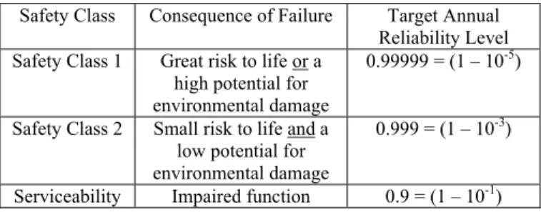
There is a further definition of two safety classes of the ultimate limit state for verifying the safety of the structure or any of its structural elements:
• Safety Class 1: for loading conditions where failure would result in great risk to life or a high potential for environmental damage. • Safety Class 2: for loading conditions where failure would result in
small risk to life and a low potential for environmental damage. To meet the design objectives for safety, target reliability levels have been established that were subsequently used for calibrating the design limit states. The target reliability levels selected are outlined in Table 1. Setting such levels is not a trivial task. Jordaan and Maes (1991) presented arguments for these values, based on other risks encountered by individuals in society. For example, in Canada the annual risk of fatality from motor vehicle accidents is about 2 x 10⁻⁴. It was proposed that a target value comfortably below this be selected, say Pf = 10
-5
for Safety Class 1 (reliability = 1 – Pf). Less demanding
levels were set for Safety Class 2 and serviceability. Other standards set similar reliability levels, e.g. NORSOK (1999) and the Joint Committee on Structural Safety (2001). Note that the CSA Standard and the noted standards use an annual probability of failure rather than a return period.
Table 1 Safety Classes and Reliability Levels
Safety Class Consequence of Failure Target Annual Reliability Level Safety Class 1 Great risk to life or a
high potential for environmental damage
0.99999 = (1 – 10-5)
Safety Class 2 Small risk to life and a low potential for environmental damage
0.999 = (1 – 10-3)
Serviceability Impaired function 0.9 = (1 – 10-1) Reliability considers both the uncertainty of loads, environmental and other, as well as the resistance or strength of the structure. Design to the prescribed reliability levels requires partial factors for both loads and the resistance. The values of the partial factors were calibrated for various loads and load combinations in a series of studies carried our by Maes (1986a and 1986b) and updated Maes et al (2004).
In addition to general requirements for design, the Standard provides guidance on describing environment conditions and the use of environmental parameters in determining environmental loads and load combinations. Environmental conditions identified include wind, air and sea temperature, snow and ice accretion, waves, currents, water level, marine growth, sea ice and icebergs, seabed geology, and earthquakes. These conditions have to be described, assessed and site-specific data assembled to quantify them.
The treatment of loads and load combinations addresses permanent loads, operational loads, accidental loads, and environmental loads.
Environmental loads are in turn sub-divided into those due to waves and current, wind, ice, and seismic effects. Environmental loads can be frequent, such as wind or wave loads, or rare, due to earthquakes or iceberg impact. These two categories of environmental loads are treated separately in the Standard.
i. Frequent environmental processes produce many loads over the course of a year. For both Safety Class 1 and Safety Class 2, specified frequent environmental loads, Ef, shall
have an annual probability of exceedance, PE, not greater
than 10-2.
ii. Rare environmental events occur less than once a year. For Safety Class 2, specified loads shall have an annual probability of exceedance, PE, not greater than 10
-2
. For Safety Class 1, specified loads shall have an annual probability of exceedance, PE that lies in the range 10
-4
to 10-3. Rare environmental loads need not be considered for events having an annual probability of occurrence of less than 10-4.
The concept of companion frequent environmental processes was introduced to provide guidance on specified loads for the simultaneous occurrence of the principal frequent environmental process or principal rare environmental event with another frequent principal environmental process. For principal processes or events such as waves, wind, current, sea ice, earthquakes or icebergs, stochastically
dependent, stochastically independent and mutually exclusive
companion frequent environmental processes were identified. Factors were given in Table 6.2 (CSA, 2004) to be applied to the specified frequent load, Ef, associated with stochastically dependent and/or
stochastically independent companion frequent environmental process and added to the loads from the principal process of event.
Table 6.3 in S471 (CSA, 20042) identifies a total of 12 load combinations for Safety Class 1 and Safety Class 2 of ultimate limits states and the serviceability limit state. For each load combination, load factors are given to be applied to the specified loads, be they permanent, operational, environmental or accidental. These loads factors were derived from the aforementioned calibration studies.
Review of Annex E - Determination of ice loads (CSA, 2004)
The past 10 years have seen substantial advancement in the understanding of ice loads as a result of a number of research projects. This has been primarily due to the analysis of data collected from numerous field measurement projects (Timco et al, 1999), with Beaufort Sea experience being most valuable, plus the addition of new data from measurements of ice forces on the Confederation Bridge (Brown, 2001). Formulations for calculating ice loads for a wide variety of pack ice conditions, based completely on this full-scale data, have been presented by Masterson and Spencer, 2000 and Masterson et al, 2003. These presentations cover both ice loads for the Beaufort Sea and for Sakhalin. The new insights and knowledge gained have been used in revising this Annex E (CSA, 2004).
Ice pressures for global design of stability of structures are broken into two categories, depending on aspect ratio (width of structure/ice thickness).
i. Low aspect ratio (narrow structure) Pressure, p, is given by
p = Cp A Dp
(1) p = pressure (MPa)
Cp = a coefficient (MPa·m2Dp)
Dp = a negative exponent
Cp and Dp can be either deterministic values or normally
distributed values that can be found in Table E.1 of Annex E (reproduced here as Table 2)
ii. High aspect ratio (wide structure) Pressure, p, is given by
p = Cp’ h Dp’
(W/h)Ep’ (2) W = nominal contact width
h = nominal ice thickness
Cp’, Dp’ and Ep’ = constants from measurement, see
Table E.2 of Annex E (reproduced here in Table 3) Table 2 Ice Pressure Coefficients for Low Aspect Ratios (W/h<10)
Coefficients Nominal Contact
Area CP(*) DP(**)
0.1m2≤A 26.9* 0 0.1m2<A≤30m2 8.5* -0.5** (Zone 1)
30m2≤A 2.7* -0.165
* For application to Zones 2 and 3, approximate coefficients have been determined in part from field measurements and supplemented by Zone 1 values modified using temperature relationships. For Zone 2, these are CP = 10.5 for A≤0.1m2, CP = 4.2 for
0.1m2<A≤30m2 and CP = 1.9 for 30m
2≤A. For Zone 3, these are C
P = 4.5 for A≤0.1m2, CP = 1.8 for 0.1m2<A≤30m2 and CP = 0.81 for
30m2≤A.
** For application to Zones 2 and 3, approximate coefficient Dp =-0.4 has been determined in part from field measurements and supplemented by Zone 1 values modified using temperature relationships. The relationships for Zones 2 and 3 should be used with caution and substantiated with field measurements where appropriate
Table 3 Constant Ice Pressure Coefficients for High Aspect Ratios (W/h>10)
Zone Aspect Ratio CP’ DP’ EP’
10≤W/h<80 1.5* -0.174 0 80≤W/h<1000 24.8* -0.174 -0.64 1
1000≤W/h 0.30* -0.174 0
* For application to Zones 2 and 3, approximate coefficients have been determined in part from field measurements and supplemented by Zone 1 values modified using temperature relationships. For Zone 2, these are CP’ = 1.25 for 10≤W/h<80, CP’ = 20.6 for 80≤W/h<1000 and CP’ = 0.25 for 1000≤W/h. For Zone 3, these are CP’ = 1.0 for 10≤W/h<80, CP’ = 16.5 for
80≤W/h<1000 and CP’ = 0.20 for 1000≤W/h . The relationships for Zones 2 and 3 should be used with caution and substantiated with field measurements where appropriate
.
Note that these changes to the definition of global ice loads, taking into account aspect ratio, lead to greater commonality with Russian codes for ice loads. The constants in the Tables 2 and 3 used for calculating global loads depend on the severity of the sea ice regime being considered. Three regimes have been defined, Zone 1 for the Arctic (annual freezing degree days 3000 to 4000 oC-days), Zone 2, Labrador Coast (annual freezing degree days approximately 2000 o C-days), and Zone 3, temperate regions such as Newfoundland and Gulf of St. Lawrence (annual freezing degree days 1200 oC-days or less) (Masterson et al, 2000). Average pressures are reduced by about a
factor of 2 from Zone 1 to Zone 2 and another factor of 2 from Zone 2 to Zone 3.
OVERVIEW OF OTHER CODES
Other codes containing detailed ice load calculation methods include the following:
Recommended Practice For Planning, Designing, and Constructing Structures and Pipelines For Arctic Conditions, API Recommended Practice 2N
SNiP 1.06.04-82, Loads and Influences on Marine Structures (from waves, vessels and ice)
VSN-41.88, Design of Fixed Ice Strengthened Platforms
Advances in the understanding of ice mechanics, ice loads and structural reaction to ice have been reflected in the development of the CSA standard for Fixed Offshore Structures, as well as in revisions to the American Petroleum Institute (API) standards.
In addition to these North American codes, joint venture companies seeking to develop oil and gas fields in Russian waters must also consider the Russian SNiP and VSN design standards. And while there are similarities among all these codes, they also differ in some respects.
Sandwell has compared the North American and Russian standards in their fundamental structural design philosophies for the determination of ice loading on structures(PERD/CHC report 11-20, 1998). The study was commissioned by the National Research Council of Canada under the Panel on Energy Research and Development program. Working with a Russian group, the Central Marine Research and Design Institute of St. Petersburg, comparisons were made of the structure and ice design provisions in the different codes in the context of both the safety and economy of the resulting structure designs. Conclusions from the above referenced report are below.
Structural Design Approach
All four codes, including the CSA code, follow a limit state design method, which calls for the proportioning of the structural components such that the factored component resistance is greater than the effects of the sum of the factored loads.
The CSA code reliability levels have previously been described. “The API limit state code, RP2A-LRFD (1993), served as one of the starting points for development of ISO DIS 19902 (2004) for fixed steel offshore structures. The notional probability of failure (i.e. when some epistemic uncertainties are excluded) is 5 x 10⁻⁵ annually (E&P Forum, 1995). The return period for design loads is specified.
“API codes have been calibrated against Gulf of Mexico experience for reliability in wave loads, and against 40+ years of field measurements and experience in Cook Inlet for ice loads.
“Most existing US platforms have been designed to API RP2A-WSD, which allows the traditional 1/3 increase in working stresses for the extreme environmental events. This results in slightly higher failure risks when the platform is de-manned and the wells secured, than for normal operations. Estimated annual failure rates are 4x10⁻⁴
for post-1978 L-1 designs, and 2x10⁻³ for L-2 designs. Substantially higher risks are expected for older, deteriorated, or damaged platforms, as borne out by hurricanes Ivan, Katrina, and Rita (Marshall, 2006).”
The limit state design format in the SNiP code is different from those in the CSA and API codes since it incorporates additional load and component resistance coefficients such as the coefficient of load reliability, coefficient of working condition and coefficient of structural reliability. The return period for the design loads is not specified. The target level of structural reliability is not apparent, nor is the uniformity in component reliability.
Ice Design Approach
A full range of modern ice load models for the calculation of ice loads resulting from all types of ice features are referenced in both the CSA and API codes. Probabilistic methods are recommended by both codes. API allows the use of deterministic methods although little guidance is provided in this respect.
In contrast the SNiP and the VSN codes appear to be limited in their ice design provisions. Only two types of ice features, namely level ice and ice ridge, are considered. Topics such as ice-induced vibration are not covered. Semi-probabilistic methods for establishing ice characteristics for ice load calculations do not appear to lead to ice loads with consistent levels of annual probability of exceedence. The following is stated in the closure of the PERD 1998 report. "The SNiP and VSN codes differ from the CSA and the API code primarily in that the return period of design extreme environmental loads is not specified and that multiple coefficients are applied to loads and component resistances. Consequently, it is not apparent if there is a target level of structural reliability. The design provisions in the SNiP and VSN codes are limited in comparison to those in the CSA and the API codes".
The approach taken by the Russian codes is likely due to the fact they were developed originally for application to the design of structures such as bridges and port facilities in rivers and have only recently been adapted to the offshore. There is considerable attention paid to the regional differences between rivers within the Russian Federation in the codes. However the offshore environment, which is dealt with in considerable detail in the CSA and the API codes, is not addressed in as much detail in the Russian codes. The Russians do have an extensive knowledge of the Arctic and the pack ice, but this knowledge has developed along different lines than it has in the West. Western practice has been reconciled with Russian practice, as presented in Masterson et al, 2003. The following was concluded: The
analysis demonstrated that Russian SNiP and Western procedures for calculating global ice crushing pressures on vertical structures are based on common principles and considerations. Both methods consider the combined effects of aspect ratio (w/t) and loaded area (w t) on the global ice pressure. Both consider as well the effect of ice thickness on the aggregate ice strength. By writing the Western equations in a different form, it is demonstrated that the two methods are virtually the same mathematically.
A major consideration in the use of either method lies in the application of full-scale ice pressure and load measurements from instrumented offshore structures in the Beaufort Sea and off the east coast of Sakhalin. These types of measurements are essential for the proper determination of design loads and pressures and ensure that the designs are neither under nor over-conservative. A final set of
equations was presented in Masterson et al 2003, which were used in ice load determinations in Monte Carlo simulations.
To demonstrate the application of the equations the following example has been worked in PERD, 1998 and is herein presented to compare the SNiP and VSN codes with the CSA S471-04. SNiP 2.06.04.82-1996 was used for the calculation.
The scenario consisted of a level ice sheet of 1.2 m thickness interacting with a fixed offshore structure in mid-winter. The ice is assumed to be moving at a velocity of 0.2 m/s and the structure is vertical sided with a width of 100m and in deep water.
From CSA S471-04, section E.6.2.4, the ice pressure and force for different zones is determined from Equation (2) where Cp’ = 1.5 MPa, Dp’ = -0.174 and Ep’ = 0 for 10≤W/h<80
which gives
Zone Ice Pressure (MPa) Force on Structure (MN)
1 1.417 170
2 1.177 141
Using SNiP
Case Force on Structure(MN) Using Formula 121 597
Using Formula 122 (for wide structure)
159
VSN yields a force of 171 MN.
Obviously, for this simple case, the loads derived from CSA, SNiP for wide structures and VSN are quite comparable. SNiP allows the use of either formula 121 or 122 and does not specify which should be used in this case. SNiP also requires that the ice sheet be divided into at least 5 layers and that a strength be assigned to each layer using information on temperature and brine volume. This involves judgment as such information is seldom available. In addition, there is a strain rate effect which must be used. Although the ice velocity was specified in this case, it is true that offshore all velocities will be experienced during an ice interaction. Thus the worst case must be considered.
VSN is a simpler code to apply. However ice strength must be derived from the assumed temperature and salinity values of the ice. A note in the PERD report says that the ice strengths from VSN are usually significantly lower than those determined in the field. It may be that they do reflect full-scale global pressures generally quite well. The ice “strength” in the worked example was 1.3 MPa, a value quite comparable to the global pressures obtained from the CSA procedure which is based on full-scale measurements.
EXPERIENCE IN APPLICTIONS
The global and local pressure relationships found in the CSA code have found application for designs in the Beaufort Sea and at Sakhalin (Masterson and Spencer, 2000 and Masterson et al, 2003). Sakhalin Energy has deployed two new-built structures based on the provisions now incorporated into the CSA. The Molikpaq structure deployed at Piltun A also incorporates the procedures for ice load calculations. Also, while not specifically following these procedures, the Orlan structure deployed in the Sakhalin 1 region at Chayvo is designed for similar loads. In the future it is likely that all structures offshore Sakhalin will use the procedures outlined in CSA, perhaps with
modification to reflect new knowledge and experience from other regions.
Measurements taken at the Molikpaq indicate that the global loads derived from the CSA procedures are reasonable, especially the design loads. First indications of this agreement are published in Weiss et al, 2001. Local pressures measured as well agree with the predicted pressures. The lessons being learned from measurement at Sakhalin is that the total count of lower loads is much less than indicated by theory. This finding has important implications for fatigue and habitability design.
SUMMARY AND CONCLUSIONS
The CSA developed a comprehensive Offshore Structures Standard which has seen international application. The code is performance based, setting overall targets for reliability and provides specific guidance on achieving these targets. The provisions in the CSA standard have been compared with the Russian codes such as SNiP and VSN, and it has been shown that they produce generally similar ice loads.
The criteria on ice loads have been developed over a number of years, drawing on experience in the Beaufort Sea, the Sea of Okhotsk and the Sakhalin Coast and finally experience in Cook Inlet Alaska. The ice load provisions have been used for the design of Sakhalin Energy structures being deployed at the Piltun-B and Lunskoye locations offshore Sakhalin.
To meet the design objectives for safety, target reliability levels have been established that were subsequently used for calibrating the design limit states. Frequent and rare environmental processes are defined in terms of return period. Safety Class 1 and Safety Class 2 structures have a specified frequent load return period of 10-2. For rare environmental events, Safety Class 2 installations shall have specified loads with an annual probability of exceedance of 10-2, while Safety Class 1 structures shall have specified loads with an annual probability of exceedance of between 10-3 and 104. In addition, companion frequent processes are specified and 12 load combinations are tabulated for both safety classes.
Regimes of ice severity have been defined, with Zone 1 delimiting areas with 3000 to 4000 C-degree days of freezing, Zone 2 delimiting areas with 2000 degree days of freezing and Zone 3 having 1200 C-degree days of freezing.
In comparing codes and standards, it was found that both the CSA and the API RP 2N reference a full range of modern ice load models for calculating ice loads. Probabilistic methods are recommended by both standards. In contrast, the SNiP and VSN codes appear to be limited in their ice design provisions. Only two types of ice features, level ice and ridged ice, are considered. Topics such as ice-induced vibrations are not addressed. Semi-probabilistic methods for establishing ice characteristics for ice load calculations do not appear to lead to loads with consistent levels of annual probability of exceedance. It is not apparent that there is a target level of reliability in these codes.
Analysis has demonstrated that the SNiP and Western procedures for calculating global ice crushing pressures on vertical structures are based on common principles and considerations. Both methods consider the effect of aspect ratio and loaded area. Both consider as well the effect of ice thickness on the aggregate ice strength.
A comparison calculation using a simple case showed the CSA, SNiP and VSN codes to yield similar ice loads.
Measurements taken at the Molikpaq structure now deployed at Sakhalin indicate that the global loads derived from CSA procedures are reasonable, especially the design loads. Local loads and pressures also agree well with predicted pressures. The frequency of lower loads is much lower than indicated by theory.
REFERENCES
Brown, T.G. (2001) “Four years of ice force observations on the Confederation Bridge”. Proc.16th Int. Conf on Port and Ocean Engineering under Arctic Conditions, Ottawa, August 12-17, 2001,
Vol.1, pp. 285-298.
CSA (2004) “S471-04 General requirements, design criteria, the environment and loads”. Published as a National Standard of
Canada in 2004 by the Canadian Standards Association, 5060 Spectrum Way, Suite 100, Mississauga, Ontario, Canada L4W 5N6.
E&P Forum (1995). “Uncertainties in the Design Process”. Offshore Structures/ Metocean Workshop at Selsdon Park, Surrey UK. Report No. 3.15/229. London: The Oil Industry International Exploration and Production Forum.
Joint Committee on Structural Safety (2001) “Probabilistic Model Code, Part 1 Basis of Design”.
JCSS-OSTL/DIA/VROU-10-11-2000, (www.jcss.ethz.ch).
Jordaan, I.J., Maes, M.A. (1991) “Rationale for load specifications and load factors in the new CSA code for fixed offshore structures”.
Can. J. Civ. Eng., Vol.18, pp. 454-464.
Maes, M.A. 1986a. A study of a calibration of the new CSA code for fixed offshore structures. Canada Oil and Gas Lands Administration, Environmental Protection Branch, Environment Canada, Ottawa, Ont., Technical Report 7.
Maes, M.A. 1986b. Calibration of design criteria in the new CSA standard for fixed offshore structures. Canada Oil and Gas Lands Administration, Environmental Protection Branch, Environment Canada, Ottawa, Ont., Technical Report 9.
Maes, M.A., Abdelatif, S. and Frederking, R. (2004) “Recalibration of partial load factors in the Canadian offshore structures standard CAN/CSAS471”, Can. J. Civ. Eng., Vol. 31, pp. 684–694.
Marshall, PW (2006) “Cost-Risk Tradeoffs – a Dirty Little Secret?” Lecture at UC Berkeley, Interdisciplinary Studies Center.
Masterson, D.M. and P. A. Spencer, 2000, “Ice Force Versus Aspect Ratio”, IUTAM Symposium -Scaling Laws in ice mechanics and Ice Dynamics, Fairbanks, Alaska, USA.
Masterson, D.M., K. Kouzmitchev, J.C.M. deWaal, 2003, “Russian SNiP 2.06.04-82 and Western Global Ice Pressures – A Comparison”, POAC ’03, Trondheim, Norway.
Masterson, D.M., R.M.W. Frederking, P.A. Truskov, 2000, “Ice Force and Pressure Determination by Zone”, Sixth International Conference on Ships and Marine Structures in Cold Regions, ICETECH 2000
NORSOK (1999) “Actions and Action Effects”, NORSOK Standard N-003, Rev. 1.
PERD/CHC Report 11-20, 1998, “Comparison of International Codes for Ice Loads on Offshore Structures”, prepared by Sandwell Engineering Inc. (with CNIMF).
Sandwell (1998) “Comparison of International Codes for Ice Loads on Offshore Structures”, Report 11-20 prepared for Program on Energy Research and Development, Ottawa, Canada.
SNiP (1995) Construction Norms and Rules SNiP 2.06.04.82* (1995) Loads and Influences on Marine Structures (from Waves, Vessels and Ice), Federal Committee of the USSR for Construction (Gostroy USSR), Moscow (published in Russian).
Timco, G. W. Johnston, M., Frederking, R. (1999) “The NRC Ice Load Catalogue”. Proc.15th Int. Conf on Port and Ocean Engineering under Arctic Conditions, Helsinki, August 23-27, 1999,
Vol.1, pp. 444-453.
Weiss, R.T., B. Wright and B. Rogers, 2001, “In-Ice Performance Of The Molikpaq Off Sakhalin Island”, Proceedings of the 16th International Conference on Port and Ocean Engineering under Arctic Conditions POAC '01, Ottawa, Ontario, Canada