ASPECTS OF HYDRODYNAMICS AND HEAT
TRANSFER IN CIRCULATING FLUIDIZED BEDS
by
Matthew R. Hyre
M.S. Mech Eng., Villanova University (1991)
B.S. Nuclear Eng., United States Military Academy, West Point (1987) Submitted to the Department of
Mechanical Engineering in Partial Fulfillment of the Requirements
for the Degree of
Doctor of Philosophy in Mechanical Engineering at the
MASSACHUSETTS INSTITUTE OF TECHNOLOGY -May 1995
© 1995 Massachusetts Institute of Tehnology All Rights Reserved
Signature of Author /
Certified by
Accepted by
Department of Mechanical Engineering 8 May 1995
Leon R. Glicksman Professor, Department of Mechanical Engineering Thesis Supervisor ...f.;;-. ,,;MASSAC;HUSEITSINSNSIUl'UTE OF TECHNOLOGY
MAR 1 9
1996
Ain A. Sonin Chairman, Departmental Committee on Graduate Studies Department of Mechanical EngineeringLIBRARIES
... • .... j
am=a~
Aspects of Hydrodynamics and Heat Transfer in Circulating
Fluidized Beds
by
Matthew Hyre
Submitted to the Department of Mechanical Engineering on May 8, 1995 in Partial Fulfillment of the Requirements for the Degree of
Doctor of Philosophy in Mechanical Engineering
ABSTRACT
Simplifications to the set of scaling parameters for dynamic similarity of fluidized beds derived from dimensional analysis of the equations of motion for a particle-fluid suspension were explored. A new set of simplified scaling laws includes the Froude number based on column diameter, the solid to gas density ratio, the ratio of superficial to minimum fluidization velocity, bed geometric ratios, and particle sphericity and size distribution. When the gas to particle drag is represented by either the Ergun equation or a single particle drag equation, the new simplified laws hold exactly in both the viscous dominated and gas inertia dominated limits. For intermediate conditions, the gas to particle drag is well approximated in models based on the simplified scaling laws. The simplified scaling laws allow very small models to be constructed which properly simulate the hydrodynamics of a full size reactor or combustor.
Experimental confirmation of the new simplified scaling laws and the viscous limit scaling parameters, where equality of the density ratio is omitted, were carried out in circulating fluidized beds. Within the viscous limit, the solid to gas density ratio is an important modeling parameter when the slugging regime is approached. In general, the solid to gas density must be matched to achieve good similarity. Using the new simplified scaling laws, good agreement was observed even when the length scale of the air fluidized model was as small as 1/16 that of an atmospheric combustor.
The parameters which govern the convective heat transfer to the wall a CFB were determined from an analysis of the non-dimensional energy equation. Experiments were performed for an evaluation of similarity in convection heat transfer between hydrodynamically and thermally similar beds. Heat transfer measurements were taken at three different bed heights in a 1/4 and 1/16 scale model of the Studsvik 2.5 MWth atmospheric circulating fluidized bed combustor. Results showed good agreement between Nusselt numbers over a range of operating conditions and bed heights.
Heat transfer to the walls of circulating beds is primarily due to conduction from clusters of particles falling along the walls. The magnitude of the heat transfer coefficient decreases with increased contact time of particle clusters at the wall. Conditions which promote more rapid cluster breakup can augment heat transfer if the fraction of the surface covered by particles is not significantly reduced. An experimental investigation was conducted to determine if bed to wall heat transfer in a circulating fluidized bed could be significantly enhanced through the use of heat transfer surfaces constructed to minimize the time of cluster contact while not drastically reducing the fraction of the wall covered by clusters. Convective heat transfer measurements were taken at three separate axial locations in a 1/16 scale cold model of the Studsvik 2.5 MWth combustor. The bed wall geometry was altered
to include small horizontal ridges placed at systematic intervals along a heat transfer panel. The use of the altered heat transfer geometries was found to increase the bed to wall heat transfer by up to 30 percent over the flat wall case. Very small amplitude roughness
elements (~ dp) were effective in disrupting wall flow.
The surface renewal model of heat transfer from a CFB was extended to include the transient aspects of the effective gas layer thickness between the wall and first layer of clusters, the contact time at the wall, and the fraction of the wall covered by clusters. The resulting model allows fro the prediction of heat transfer from a surface including uniformly spaced horizontal ridges which has been designed to augment the heat transfer by controlling the time a cluster remains at the wall.
A numerical model of the solids flow and distribution within a circulating fluidized bed is developed. The model is based on a Lagrangian simulation for determining particle dispersion. In this approach, dispersion effects are determined by tracking particles through a continuous succession of turbulent eddies superimposed upon the mean gas flow. Each eddy is characterized by a mean time and length scale, and the velocity fluctuations are randomly generated in a Gaussian manner as a particle enters an eddy. This approach results in a Monte-Carlo procedure where many particle trajectories (realizations) must be computed to obtain averaged properties. The simulation includes the effects of particle inertia, 'crossing-trajectories,' particle sphericity, bed voidage, and particle-particle interactions. Calculated dispersion coefficients are then used to predict the average dilute phase axial solid fraction profile in the core of a CFB. Overall mass and momentum equations for the core-annular structure of a CFB are solved to determine the annular layer thickness, voidage, and fall velocity. Model results are in good agreement with experimental data for CFB's, and FCC reactors.
Previous research has shown the diameter of a circulating fluidized bed has a significant effect on the heat transfer rates to peripheral walls. In order to understand the effect of bed diameter on heat transfer, two laboratory-sized scale models were built and run at room temperature. The two units were the same height and were run at the same operating conditions with the same particles; the only difference was that the diameter of the second unit was 50% larger than that of the first. The two scale models were designed to simulate the hydrodynamic behavior of pressurized CFB's 14.3 m tall with diameters of 0.33 m and 0.50 m respectively. To compare the effect of bed diameter on heat transfer, the fraction of the wall covered by clusters of particles was measured. The coverage of the wall by clusters was determined from visual data recorded with a digital high-speed video camera through the transparent wall, with subsequent measurements using image-analysis software. The results show that a 50% increase in bed diameter can nearly double the fraction of the wall covered by clusters. Using the surface renewal model of heat transfer from a CFB, an increase in the convective heat transfer (excluding radiation) of up to 60% can be predicted due to the increase coverage of the wall by clusters.
Thesis Committee:
Prof. Leon R. Glicksman (Chairman) Prof. Peter Griffith
Prof. John H. Lienhard Prof. Adel F. Sarofim
ACKNOWLEDGMENTS
I would like to thank Prof. Leon Glicksman for his support and guidance during the past four years. The confidence he expressed in allowing me to shape the direction of much of this thesis made for an enjoyable stay at MIT. Any criticisms as to the length or shape of
this thesis should be directed entirely at the author.
Many students directly influenced the ideas and paths taken in this thesis. For those ideas which turned out to be really lousy and those paths which were dead ends, I'm sure their influence was entirely unintentional. With this disclaimer, thanks go to members of the MIT Fluidization Group during the course of this work: Peter Noymer, Mike Lints, and Tom Yule. I would especially like to thank Paul Farrell and Detlef Westphalen with whom I worked closely over the course of this thesis. The many discussions and debates we had were an invaluable addition to my education -even the few about fluidized beds.
Finally, I wish to express my deepest thanks for my soon-to-be-wife, Wendy. She kept all night vigils for me during the weeks before the qualifying exams, and put up with ranting tirades during the more frustrating times of this project. Additionally, Wendy endured the rough draft, in inebriated monologue form, of everything contained in this document at one time or another. Her love and understanding were truly inspiring.
This project was funded by several agencies. The support of the Electric Power Research Institute, DOE METC, and the National Science Foundation is greatly appreciated.
TABLE OF CONTENTS
ABSTR ACT...
3
ACKNO\ wLEDGEMENTS...
5
TABLE OFCONTENTS...
...
7
CHAPTER 1
GENERAL INTRODUCTION
TABLE OF CONTENTS
1.0
INTRODUCTION...28
2.0
FLUIDIZATION REGIMES...32
3.0
OVERVIEW OF CFB HYDRODYNAMIC MODELS...34
3.1
Simple Axial Distribution Models ... 35
3.2
Core/Annulus Models... 37
3.3
CFD Techniques... ... 38
4.0
CONCLUSIONS ON CFB MODELS ...
...
5.0
STUDY GOALS...
40
CHAPTER 2
HYDRODYNAMIC SCALING FOR
CIRCULATING FLUIDIZED BEDS
TABLE OF CONTENTS
1.0
INTRODUCTION...
...
... 46
2.0
DERIVATION OF SCALING RELATIONSHIPS ...52
2.1
Introduction ...
52
2.2
Mixture Theory Equations...
52
2.3
Ensemble Averaging ...
... 54
2.4
Constitutive Relations...
60
2.4.1
Particle Pressure ...
60
2.4.2
Steady-State Momentum Exchange
Between Phases ... 62
2.4.3
Unsteady-State Momentum Exchange
Between Phases ... 65
2.5
Non-Dimensionalization of the Two
Fluid Equations ...
66
2.6
Evaluation of Coefficients for Finite
Reynolds Numbers (CH, CA, CD)...
68
2.7
Governing Parameters in Core Region of a CFB ... 70
2.8
Governing Parameters Near the Wall of a CFB ... 71
2.9
Boundary Conditions ... 73
2.10 Development of the Scaling Laws Using the Single
Particle Equations of Motion... ... .. 74
2.10.1
Core Region of a CFB or Freeboard
Region of a Bubbling Bed...75
2.10.2
Single Particle Equation of Motion Near a Solid
Boundary ...
78
2.10.3
Boundary Conditions ...
80
2.11 Other Forces ... 81
2.11.1
Brownian Movement ...
81
2.11.3
Van der Waals Forces ...
82
2.11.4
Particle-Wall Collisions ...
86
2.11.5
Particle-Particle Collisions ...
86
2.11.6
Electrostatics ...
.... 90
2.11.6.1
Electrostatic Forces Between
Particles ...
... ....
90
2.11.6.2
Charged Particles Near the Wall
of a Fluidized Bed ... 92
2.12 Full Set of Scaling Parameters...95
2.13 Calculation of Scale Model Operating Conditions
Using the Full Set of Parameters ... 95
2.14 Experimental Verification of Full Set
of Scaling Parameters ... 100
3.0
SIMPLIFICATIONS TO THE FULL SET
OF SCALING PARAMETERS ...
103
3.1
Introduction ...
103
3.2
General Simplifications ...
103
3.3
Viscous Limit Scaling...
...
106
3.4
Inertial Limit Scaling ...
...
... 108
3.5
Generalized Simplified Scaling Parameters...
... 109
3.5.1
Low Reynolds Number ... 111
3.5.2
High Reynolds Number ...
.... 112
3.5.3
Low Slip Velocity ...
113
3.5.4
General Case ...
114
3.5.5
Clusters ...
119
3.5.6
Terminal Velocity of Particles ... 123
3.6
Conclusions ...
127
4.0
EXPERIMENTAL ARRANGEMENTS FOR
VERIFYING SIMPLIFIED SCALING
PARAMETERS...128
4.1
Introduction ... 128
4.2
Dimensions and Construction of Cold Beds ... 129
4.2.1
1/4 Scale Model of the UBC Pilot
Scale Combustor...
....
... 129
4.2.1.1
Main Bed Test Section... ... 132
4.2.1.3
Solid Return Leg ... 136
4.2.2
1/4 Scale Model of the 2.5 MWt Studsvik
Circulating Fluidized Bed Combustor ... 138
4.2.2.1
Main Bed Test Section...138
4.2.2.2
Primary Separator and Downcomer...140
4.2.2.3
Secondary Separator and Return Leg.... 145
4.2.2.4
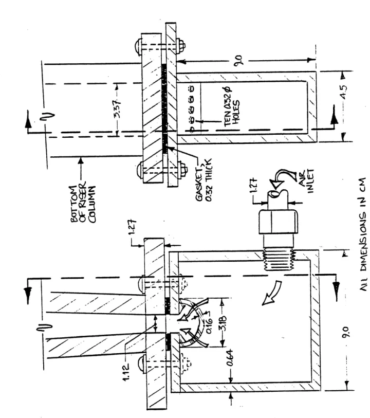
Distributor Box and Boot ... 147
4.2.3
1/16 Scale Model of the 2.5 MWt Studsvik
Circulating Fluidized Bed Combustor...147
4.2.3.1
Main Bed Test Section ... 150
4.2.3.2
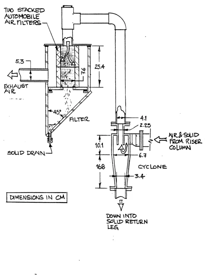
Primary Separator ... 153
4.2.3.3
Solid Downcomer and Return Leg ... 153
4.2.4
1/2 Scale Model of the Foster Wheeler Pilot
Second Generation Pressurized CFB ... 155
4.2.4.1
Foster Wheeler Hot Bed... 155
4.2.4.2
1/2 Scale Model of the Foster
Wheeler Hot Bed...
161
4.3
Bed Solids Materials ...
163
4.3.1
Basis of Selection for Steel ...
164
4.3.2
Steel Density Measurements ... 165
4.3.3
Preparation of Steel Powders...165
4.3.4
Selection of Glass Powders ... 169
4.3.5
Selection of Plastic Powders...172
4.3.5.1
Plastic Powders for Viscous Limit
and Cold Bed Scaling... 172
4.3.5.2
Plastic Powders for Scaling the Foster
Wheeler Pressurized Combustor ... 175
4.3.6
Preparation of Glass and Plastic Particles...176
4.3.7
Elimination of Static Electricity Effects ... 177
4.4
Variable Measurement ...
178
4.4.1
Air Flow ...
178
4.4.1.1
1/4 Scale UBC Bed... 178
4.4.1.2
1/16 Scale Studsvik Bed... 178
4.4.1.3
1/4 Scale Studsvik Bed ... 179
4.4.1.4
1/2 Scale Foster Wheeler Bed...179
4.4.2
Solid Circulation ... 179
4.4.2.2
1/16 Scale Studsvik Bed...182
4.4.2.3
1/4 Scale Studsvik Bed ... 182
4.4.2.4
1/2 Scale Foster Wheeler Bed ... 182
4.4.3
Pressure Measurement...183
4.4.3.1
1/4 Scale UBC Bed ... 183
4.4.3.2
1/16 Scale Studsvik Bed... 184
4.4.3.3
1/4 Scale Studsvik Bed ... 185
4.4.3.4
1/2 Scale Foster Wheeler Bed... 185
4.5
Uncertainty Analysis ...
187
4.5.1
Air Flow ...
187
4.5.2
Solid Circulation Rate ... ... 188
4.5.3
Pressure Measurements ...
193
4.5.4
Sensitivity of Solid Fraction Profiles ... 195
4.5.5
Hot Bed Measurements ...
197
4.5.5.1
Solid Circulation Measurements ... 197
4.5.5.2
Air Flows ...
... 199
4.5.5.3
Pressure Measurement... 201
4.6
Data Reduction ...
205
4.6.1
Average Solid Fraction Profiles...205
4.6.2
Pressure Fluctuation Data...205
4.6.2.1
Probability Density Functions ... 205
4.6.2.2
Power Spectral Densities... 206
5.0
RESULTS OF VISCOUS LIMIT SCALING ... 207
5.1
Viscous Limit Scaling Between Steel and Glass ... 210
5.1.1
Solid Fraction Profiles ...
210
5.1.2
Histograms...210
5.1.3
Power Spectral Densities...221
5.1.4
Discussion of Results ...
228
5.2
Viscous Limit Scaling Between Glass and Plastic ... 234
5.2.1
Solid Fraction Profiles...237
5.2.2
Histograms...
...
237
5.2.3
Power Spectral Densities ...
238
5.2.4
Discussion of Results ...
253
6.1
Scaling with Glass Particles ...
256
6.1.1
Solid Fraction Profiles ...
260
6.1.2
Histograms...260
6.1.3
Power Spectral Densities ...
260
6.1.4
Discussion of Results ...
274
6.2
Scaling with Plastic Particles ...
275
6.2.1
Solid Fraction Profiles...275
6.2.2
Histograms...278
6.2.3
Power Spectral Densities ...
278
6.2.4
Discussion of Results ...
292
6.3
Hydrodynamic. Scaling in Choked Beds...293
6.3.1
Yang Correlation (1975, 1983) ...
296
6.3.2
Discussion of the Parameters Governing
the Yang Correlation
...
...
298
6.3.3
Correlation of Yousfi and Gau (1974)...298
6.3.4
Discussion of the Parameters Governing
the Yousfi and Gau Correlation ...
300
6.3.5
Discussion of Analysis...301
7.0
SCALING THE STUDSVIK HOT BED COMBUSTOR
USING THE SIMPLIFIED SCALING PARAMETERS...302
7.1
Solid Fraction Profiles...310
7.2
Histograms...310
7.3
Power Spectral Densities...310
7.4
Discussion of Results ...
334
7.5
Discussion of Discrepancies with the CFB Scaling
Parameters Developed by Horio
et
al. ...
336
7.5.1
Description of the Model...
...
336
7.5.2
Results of Experiments Conducted by
Horio et al. ...
336
7.5.3
Discussion of the Assumption of Minimum
Energy Dissipation in CFB's ...
337
7.5.3.1
History of the Assumption of Minimum
Energy Dissipation...339
7.5.3.2
Energy Dissipation in Suspensions of
Neutrally Buoyant Bodies...339
7.5.3.3
Energy Dissipation in Suspensions of
Non-Neutrally Buoyant Bodies ... 341
7.5.3.4
Extremum Principles for Particle/
Fluid Systems... 3
7.5.3.5
Thermodynamic Aspects...344
7.5.3.6
Conclusions...345
8.0
SCALING PRESSURIZED FLUIDIZED BEDS USING
THE SIMPLIFIED SCALING PARAMETERS...346
8.1
Introduction
8.2
Solid Fraction Profiles...
...
... 346
8.3
Histograms... 351
8.4
Power Spectral Densities...
...
...
351
8.5
Discussion and Conclusions ... 378
9.0
REFERENCES... ...
380
APPENDICES
APPENDIX A:
APPENDIX B:
APPENDIX C:
APPENDIX D:
APPENDIX E:
APPENDIX F:
APPENDIX G:
APPENDIX H:
MINIMUM FLUIDIZATION TESTS ... 397
PRESSURE TRANSDUCER
CALIBRATIONS...
408
ROTAMETER CALIBRATION...O...413
PARTICLE CHARACTERIZATION ... 418
VISCOUS LIMIT EXPERIMENTAL DATA ... 425
SIMPLIFIED SCALING HYDRODYNAMIC
AND HEAT TRANSFER DATA ...
434
HYDRODYNAMIC DATA FOR HOT
BED SCALING ...447
HYDRODYNAMIC DATA FOR FOSTER
WHEELER PRESSURIZED HOT BED
SCALING ...
463
CHAPTER 3
THERMAL SCALING FOR
CIRCULATING FLUIDIZED BEDS
TABLE OF CONTENTS
1.0
INTRODUCTION...
473
2.0
GOVERNING EQUATIONS FOR HEAT TRANSFER ... 475
3.0
GAS CONVECTION COMPONENT...
480
4.0
HEAT TRANSFER SURFACE GEOMETRY...481
5.0
HEAT TRANSFER SCALING PROCEDURES...482
6.0
INCOMPLETE THERMAL SCALING
*...4847.0
COMPARISON BETWEEN COLD BEDS ...
485
8.0
METHOD OF EXPERIMENTAL VERIFICATION
OF HEAT TRANSFER SIMILARITY...
... 488
9.0
EXPERIM ENTAL ARRANGEM ENT...489
9.1
Heat Transfer Panel Dimensions and Installation ... 489
9.1.1
Heat Transfer Panel for the 1/16 Scale Bed ...489
9.1.2
Heat Transfer Panel for the 1/4 Scale Bed...491
9.2
Heat Transfer Measurements ...
493
9.2.1
1/16 Scale Studsvik Bed ...
.. 493
9.2.2
1/4 Scale Studsvik Bed ...
494
9.3
Uncertainty in Temperature Measurements ... 497
9.4
Data Reduction for Heat Transfer Coefficients ... 497
10.0 EXPERIMENTAL RESULTS OF CONVECTIVE HEAT
TRANSFER SCALING WITH GLASS...499
11.0 DISCUSSION OF RESULTS FOR HEAT TRANSFER
SCALING WITH GLASS...
... 506
12.0 EXPERIMENTAL RESULTS OF CONVECTIVE HEAT
TRANSFER SCALING WITH PLASTIC ... 511
13.0 DISCUSSION OF RESULTS FOR HEAT TRANSFER
SCALING WITH PLASTIC ...
518
14.0 LIMITATIONS OF THE AVERAGE BED DENSITY/
NUSSELT NUMBER FUNCTIONAL RELATIONSHIP ... 524
14.1 Scaling Heat Transfer Data to Large Commercial Units...524
14.2 Heat Transfer Data at the Transition to Dilute
Pneumatic Conveying ... 524
15.0 POSSIBILITY OF HEAT TRANSFER ENHANCEMENT
BY WALL GEOMETRY MODIFICATIONS...532
16.0 CORRELATION OF ALL HEAT TRANSFER DATA
AGAINST BED CROSS-SECTIONAL VOIDAGE...536
CHAPTER 4
HEAT TRANSFER ENHANCEMENT IN
CIRCULATING FLUIDIZED BEDS
TABLE OF CONTENTS
1.0
INTRODUCTION...
543
2.0
EX PER IM EN TAL ARRANGEM ENT ...
545
2.1
Dimensions and Construction of the Cold CFB ...
545
2.1.1
Main Bed Test Section ...
547
2.1.2
Primary Separator ...
...548
2.1.3
Solid Downcomer and Return Leg ... 550
2.2
Heat Transfer Panel Dimensions and Installation ... 550
2.2.1
Smooth Wall Heat Transfer Surface ...
... 551
2.2.2
Ridged Heat Transfer Surfaces ...553
2.3
Bed Solids M aterial ...
...553
2.3.1
Preparation of Glass Particles...555
2.3.2
Elimination of Static Electricity Effects ...
556
2.4
Variable Measurement ... 556
2.4.1
Air Flow ...
...
556
2.4.2
Solid Circulation ... 557
2.4.3
Pressure Measurement...558
2.4.4
Heat Transfer Measurements ... 558
2.5
Uncertainty Analysis ... ... 561
2.5.1
Air Flow ...
...
...
561
2.5.2
Solid Circulation Rate ...562
2.5.3
Pressure Measurements ...564
2.5.4
Temperature Measurements ... 565
2.6
Data Reduction ...
...
567
2.6.1
Average Solid Fraction Profiles ... 567
2.6.2
Heat Transfer Coefficients...567
3.1
Flat Wall Tests ...
569
3.2
Ridge Spacing = 20 mm ...
572
3.3
Ridge Spacing = 10 mm ... 575
3.4
Ridge Spacing = 5 mm. ...
... 578
3.5
Discussion of Results ...
581
3.5.1
Effect of Solids Circulation Rate ...
... 581
3.5.2
Effect of Bed Height ... 584
3.6
Effect of Ridge Spacing...584
3.7
Effect of Ridges on Bed Hydrodynamics...586
4.0
HEAT TRIANSFER MODEL ...
588
4.1
Convective Heat Transfer ...
... 588
4.2
Radiation ...
...
... 591
4.3
Overall Heat Transfer Model...592
4.4
Evaluation of Heat Transfer Parameters ... 593
4.4.1
Cluster Void Fraction ...
593
4.4.2
Time of Contact Between Wall and Cluster...594
4.4.3
Effective Gas Layer Thickness Between
Wall and Cluster ...
617
4.4.4
Fractional Wall Coverage ... 635
4.4.5
Dilute Phase Heat Transfer Coefficient ...654
4.4.6
Effective Emissivity of the Cluster Surface ...
654
5.0
COMPARISON OF EXPERIMENTAL RESULTS
WITH THE MODEL...o...
.
... 655
5.1
Flat Wall Tests ...
657
5.2
Ridge Spacing = 20 mm ... 657
5.3
Ridge Spacing = 10 mm...
... 659
5.4
Ridge Spacing = 5 mm...
660
5.5
Summary ...
661
5.6
Comparison of Heat Transfer Model Results for Various
Ridge Spacings ... 662
5.7
Sensitivity to Cluster Voidage ... 667
5.8
Sensitivity to the Cluster Standoff Distance ... 670
5.9
Sensitivity to the Fraction of the Wall
Covered by Clusters ...
673
5.11 Sensitivity to the Initial Fractional Wall Coverage ...
679
5.12 Sensitivity to the Dilute Phase Heat Transfer Coefficient...682
6.0
CONCLUSIONS AND RECOMMENDATIONS ... 684
7.0
REFERENCES...685
APPENDICES
APPENDIX A:
APPENDIX B:
APPENDIX C:
HEAT TRANSFER DATA ... 693
PRESSURE TRANSDUCER CALIBRATIONS ... 702
CHAPTER 5
THE HYDRODYNAMIC MODELING OF
CIRCULATING FLUIDIZED BEDS
TABLE OF CONTENTS
1.0
INTRODUCTION...
712
1.1
Eulerian Models...
12
1.2
Lagrangian Models ...
716
2.0
DETERMINATION OF DISPERSION COEFFICIENT ... 718
2.1
Structure of Gas Turbulence ... 18
2.2
Determination of Particle Mean Square Displacement ... 720
2.2.1
Result for Vanishing Particle Reynolds Number ... 721
2.2.2
Solution for Non-Vanishing Particle
Reynolds Numbers ...
722
2.3
Evaluation of Particle Dispersion Coefficient ... 727
2.4
Determination of Average Bed Axial Solid
Concentration Profile ... 728
2.4.1
Derivation of Dispersion Equation ... 728
2.4.2
Source Term ... 730
2.4.3
Boundary Conditions ... 731
2.5
Solution of the Two Dimensional Dispersion Equation ... 733
2.6
Case of Constant Concentration at the Wall ... 741
2.7
Entrainment Model....
...
... 744
2.8
Determination of
...
...
...
746
3.0
MODEL ENHANCEMENTS...
3.1
Particle-Particle Collisions .. ...
...
...
747
3.1.1
Limit 1: Viscous Relaxation Time < Time
Between Particle Collisions ...
749
3.1.2
Limit 2: Time Between Collisions < Viscous
Relaxation Time...754
3.1.3
Modifications to the Radial Dispersion Coefficient
Due to Particle Collisions ... 759
3.1.4
Modifications to the Average Axial Concentration
Profile Due to Particle Collisions ... 762
3.2
Gas Turbulence Modification ...
764
3.2.1
Particle-Eddy Interaction ...
7...
67
3.3
Drag Coefficient ...
...
775
3.3.1
Determination of Drag as a Function of
Solid Fraction...
... ...
776
3.3.2
Effect of Particle Sphericity on Drag ... 782
4.0
OVERALL CFB HYDRODYNAMIC MODEL...790
4.1
Development of the Mass and Momentum Equations
for the Core and Annulus ... 790
4.2
Initial Conditions...
... 797
4.3
Collection Efficiency of Exit...800
4.4
Determination of
d
dz.
d dz...
...800
4.5
Determination of
... 801
4.6
Determination of ... 802
5.0
RADIAL PARTICLE DISTRIBUTION IN DILUTE
REGIONS OF CIRCULATING FLUIDIZED BEDS...804
5.1
Model Formulation...
..
...
... 804
5.2
Particle Velocity Distributions ... 807
5.3
Radial Concentration Distribution ...
10
5.4
Pressure Drop ... ... 813
5.5
Estimation of the Exponent 'n'... 815
5.6
Sum m ary ... ...
818
6.0
ROLE OF CLUSTERS ...
820
6.1
Axial Cluster/Particle Movementt...
822
6.2
Determination of the Relative Importance of Particle
Axial Convection and Particle Axial Dispersion ... 823
6.2.1
Experimental Measurements of Axial Particle
Dispersion in CFB's ... 823
6.2.2
Summary of Experimental Axial Solids
Dispersion Data ...832
6.3
Evaluation of Axial Particle Flux Due to Dispersion
and Convection ...
833
6.4
Evaluation of Dir and Di ... 834
6.4.1
Experimental Determination of epr ...
834
6.4.2
Summary of Experimental Radial Solids
Dispersion Data ...
... 841
6.5
Determination of Cluster Dispersion Coefficient ... 842
6.5.1
Determination of Initial Cluster Velocity ... 845
6.5.2
Recording Data...846
6.5.3
Data Interpretation ... 846
6.6
Evaluation of Dia and Dicl...850
6.6.1
Evaluation of Dir ... 851
6.6.2
Evaluation of Dia ... 851
7,0
EFFECT OF THE BOUSSINESQ-BASSET
HISTORY TERM...,..852
7.1
Introduction ... 852
7.2
Particle Equation of Motion ... 852
7.3
Solution of the Equation of Motion...855
7.4
Results...
... 856
8.0
SUMMARY OF CFB HYDRODYNAMIC MODELING
...
860
8.1
Determination of the Lateral Solids Dispersion Coefficient...860
8.2
Axial Concentration Profile ... ...862
8.3
Particle Collisions ... 864
8.4
Gas Turbulence Modification ... 865
8.5
Expression for Particle Drag ...
866
8.6
Overall CFB Hydrodynamic Model ... 867
8.6.1
Initial Conditions
-
Conditions at the Riser Exit...869
8.6.2
Determination of dmc-,
da,_...
--. .... ....871
dz dz
8.6.3
Determination of ... 871
8.6.4
Determination of
...
872
8.7
Radial Distribution of Solids in Dilute Region of CFB...872
9.0
NUMERICAL SOLUTION STRUCTURE ...
874
9.1
Required Input ... 874
9.2
Determination of Lateral Solids Dispersion Coefficient...874
9.3
Determination of Axial Disperse Phase
9.4
Overall CFB Hydrodynamic Model...877
9.5
Radial Solids Distribution ...
877
10.0 MODEL RESULTS ... 87
10.1 Comparison of Experimentally Determined Lateral
Dispersion Coefficients in CFB's with the Numerical
Model ... 879
10.2 Estimated Mixing Times in CFB's ... 887
10.3 Comparison of Experimentally Determined Hydrodynamic
Data in Cold Model CFB's with the Numerical Model ... 888
10.3.1
Axial Solid Fraction Profiles...889
10.3.2
Radial Solid Fraction Profiles ... 893
10.3.3
Radial Velocity Profiles ...
898
10.4 Comparison of Experimentally Determined Hydrodynamic
Data in CFB Combustors with the Numerical Model ... 907
10.5 Effects of Operating Conditions ... ... 914
10.5.1
Bed Diameter ... 914
10.5.2
Particle Diameter...
...
915
10.5.3
Bed Pressure ... 9 17
10.5.4
Particle Collisions ... 919
10.5.5
Coefficient of Restitution ... 920
10.5.6
Gas Turbulence Modulation ...
...
921
11.0 RADIAL FLUX MODEL...923
11.1 Introduction ...
923
11.2 Verification of Radial Flux Model ... 926
11.2.1
Bolton and Davidson Deposition Coefficients ... 926
11.2.2
Decay Coefficients of Kunii and Levenspiel ... 928
11.3 CFB Radial Solid Flux Measurements ... 934
12.0 REFERENCES...937
CHAPTER 6
THE
INFLUENCE OF BED DIAMETER
ON HYDRODYNAMICS AND HEAT
TRANSFER IN CIRCULATING
FLUIDIZED BEDS
TABLE OF CONTENTS
1.0
INTRODUCTION... 952
2.0
HEAT TRANSFER MODEL
... 953
3.0
EXPERIM
ENTAL
ARRANGEMENT...955
3.1
Dimensions and Construction of Cold CFB's
...955
3.2
Bed Solid M aterials
...
... 958
3.2.1
Preparation of Plastic
Particles...960
3.2.2
Elimination of Static Electricity Effects
...
960
3.3
Variable Measurement
...
960
3.3.1
Solid Circulation
...
961
3.3.2
Pressure
Measurement...e
961
3.4
Uncertainty Analysis
... 962
3.4.1
Air
Flow ...
962
3.4.2
Solid Circulation Rate
... 963
3.4.3
Pressure Measurements
...
963
3.5
Hydrodynamic Data Reduction
...
964
4.0
EXPERIMENTS
AND
RESULTS...965
4.1
Visual Experiments
... 965
4.2
Results...
...
...
965
5.0
CONCLUSIONES...
978
ORGANIZATION OF THESIS
This thesis is divided into five distinct chapters, each of which has numerous sections. The
chapters were written to stand alone such that the reader can skip from one to another
without a loss of continuity. The nomenclature is defined within the text of each chapter.
The figures and equations are numbered consecutively within each section of each chapter.
The following provides a brief description of each chapter and its importance relative to the
rest of the thesis. Additionally, the more important Sections in the chapters are pointed out.
Chapter One: General Introduction
This chapter provides an overview of the circulating fluidized bed technology and compares
it to other conventional combustion technologies. Those who already have a good
understanding of the main components and operation of CFB's can skip this chapter.
Chapter Two: Hydrodynamic Scaling
This chapter describes the major effort of this thesis. Section 2 provides a rigorous
development of the complete set of scaling parameters. For those not interested in the math,
it is suggested that you skip to section 2.12. Section 3 presents how the "complete" set of
scaling parameters were simplified for use in the scaling studies in this thesis. This is the
most important theoretical section in this chapter. Section 4 describes the experimental
equipment used. The final 4 sections present the verification of the parameters developed in
section 3. The more important verifications were done on hot combustors (sections 7 and
8).
Chapter Three: Thermal Scaling
This chapter is essentially an extension of chapter 2. It is fairly short and easy to read. It
extends the hydrodynamic scaling parameters to include thermal scaling parameters.
Chapter Four: Heat Transfer Enhancement
This chapter is based on a study which was a direct result of interesting phenomena
discovered during the thermal scaling. It is the least important part of the thesis. The
ultimate conclusion reached from this section is that one can increase the heat transfer
between the CFB bed and wall by placing horizontal ribs on the wall. Theory and
experimental results are presented which support this conclusion. The most important
section in this chapter is section 3, which describes the experimental results for the different
wall geometries.
Chapter Five: CFB Hydrodynamic Modeling
This chapter represents an attempt to model the hydrodynamics in a CFB through a
simplified numerical scheme. Regardless of all the simplifying assumptions made. It is
still a rather difficult chapter to read. The most important sections in this chapter are
sections 2 (which describes the dispersion model), 4 (which describes the global CFB
model), and 10 (which represents the results). Additionally, a summary section (section 8)
is included so that one can skip the complex derivations and proceed right to this sections.
Chapter Six: Effect of Bed Width on CFB Hydrodynamics
The preliminary results of a study aimed at determining the effects of bed width on
hydrodynamic phenomena in CFB's are presented in this chapter. The study is specifically
aimed at determining the relationship between bed width and bed-to-wall heat transfer.
CHAPTER 1
1.0 INTRODUCTION
A circulating fluidized bed is a device for generating steam by burning fossil fuels in a furnace operated under a special hydrodynamic condition: fine solids are transported through the furnace by gas flowing at a velocity exceeding the average terminal velocity of the particles, yet at a low enough velocity to allow a degree of refluxing of solids adequate to ensure uniformity of temperature in the furnace. CFB systems were first developed and applied commercially in the early 1940's for the fluid catalytic cracking processes and functioned as chemical reactors.
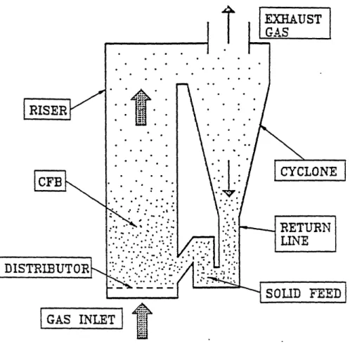
Figure 1.1 illustrates the basic components of a CFB system. The component of major interest in the CFB is the vertical riser, wherein the desired gas solid contacting is achieved. Solids introduced at the base of the riser are entrained by means of upflowing gas. The resulting gas-solid suspension within the riser forms the CFB. This gas-solid suspension then exits the top of the riser and enters a gas solid separation system, indicated as a cyclone. The captured solid particles are then returned back into the base of the riser by means of a return line and solid feed system to complete the closed-loop path of the solid particle flow. The gas makes only a single pass through the riser and exhausts through the top of the cyclone.
The creation of the special hydrodynamic conditions of particle refluxing, is the key to the CFB process. The combination of gas velocity, solids recirculation rate, solids characteristics, volume of solids, and the geometry of the system gives rise to this special hydrodynamic conditions under which solid particles are fluidized at a velocity greater than the terminal velocity of individual particles. Yet these particles are not entrained immediately as expected in pneumatic transport systems. Solids move up and down in the form of aggregates, causing a high degree of refluxing. These aggregates are continuously formed, dispersed, and formed again.
+ý
IT
A TTCF
I
RISER
CFB
DISTEIBUTOBI
GAS INLET
Figure 1.1: Basic Components of a CFB System
··· ·· .~.~.~'· " ·.·.:~ ~··.~··.. .-~·.··. ·· ·· ·:.. ·· ·... ··. ··. ' " ~c~'' ·· ''' "' ~~:' · .r·· " :~ii·. ·.. ·. ·II `""";' '~i:· " ~·· ·.. ·'' r ' '· " · · t ~ " · · :·. " :~· C:':t·'; . r .. ;.· ~,. ... ·. · ·: Z ;ti · ·· · ' ,i r ., :· t .... ~ ... ;' E " :.04 " ' .·~ ·. : .· · · h. .. ·2' ''''-·f' '·· :~''· · · r· ·JI. · · ~ :··· I: " " ·. · · ~t ~-r w. · ~ :`· ~: ' ·''' ·- ""' ... i·d ·-~li· '' -···· · ··C~i· · · · " n;~ · ·C-~s~t~ tT ~ t
I-
"
."
-r
FIXED BED BU8BLING SLUG FLOW TURBULENT FAST PNEUMATIC OR 1 REGIME REGIME FLUIOIZATION CONVEYING
DELAYED V
BUBBLING AGGREGATIVE FLUIDIZATION
INCREASING U.
Figure 1.2:
Vertical Gas-Solid Flow Regimes
29
t
·( ·=
·'
i · ·. · ' '· i ,, i, Pz .'I ·CFB boilers have a number of features that make them more attractive than other solid fuel fired boilers. These features include:
1. Fuel flexibility due to excellent gas-solid and solid-solid mixing
2. High combustion efficiency due to good gas-solid mixing, high burn rates, and recycling of unburned fuel particles back to the furnace
3. Efficient sulfur removal due to high gas residence times, small sorbent sizes and good gas-solids mixing
4. Low NOx emissions due to the staging of combustion
5. Small furnace cross section because of the high heat release rates due to high superficial gas velocities and intense gas-solid mixing
6. Fewer fuel feed points required because of the good gas-solids mixing in the bottom of CFB's along with the extended combustion zone
7. Good turndown and load following capability by adjusting the solids recycle rate
Table 1.1: Comparison of Combustor Technologies
Characteristic Stoker Bubbling Circulating Pulverized
Height of bed or 0.2 1 - 2 15 - 40 27 - 45 fuel burning zone Superficial 1.2 1.5 - 2.5 4-8 4-6 velocity (m/s) Excess air 20 - 30 20 - 25 10 - 20 15 - 30 Grate heat 0.5 - 1.5 0.5 - 1.5 3-5 4-6 release rate (MW/m2)
Turn down ratio 4:1 3:1 3-4:1
Combustion 85- 90 90-96 95- 99 99
efficiency
NOx emission 400 - 600 300 - 400 50 - 200 400 - 600
(ppm)
SO2 capture in None 80 - 90 80 - 90 Small
furnace (%)
Atmospheric pressure CFB technology has matured to the point where manufacturers are offering units of up to 300 MW size which are designed to meet all current thermal and emissions requirements. Pressurization of CFB's, however, is a relatively new technology with only pilot scale plants in operation, and a few utility scale plants currently planned. Significant construction and design is underway or has been completed despite deficiencies in the understanding of heat transfer and hydrodynamic in CFB's. Instead of using theoretical models, manufacturers extrapolate to larger designs based on past experience.
A major issue facing developers of new technologies is the risks associated with scaling developmental and demonstration facilities to large commercial plants successfully. In order to qualify for performance guarantees, as well as financing in many cases, developers are often conservative in scaling to larger unit sizes, resulting in a longer development-to-commercial time. Issues associated with scaling to larger sized combustion systems includ heat release and heat transfer -which effect thermal efficiencies, combustor hydrodynamics
-which can effect both combustion and environmental efficiency, boiler operability, and availability.
To reduce scaling risks and accelerate commercialization of new technology physical models can be developed to simulate larger designs for very low costs, and can provide basic information as to the hydrodynamics, erosion potential and heat transfer characteristics of new designs. This not only provides data for validating a specific plant design, but can also be used to improve operability and performance of existing and new plants.
In the last decade, the concept of properly scaled cold experimental models to simulate the hydrodynamics and heat transfer of a hot bed combustor has been put forward [Nicastro and Glicksman, (1984), Glicksman et al. (1993)]. Results have shown that a suitably designed cold fluidized bed can closely simulate the behavior of an atmospheric combustor. Proper scaling involves the use of particles and bed dimensions so that the controlling dimensionless parameters are equal for the hot and cold bed.
2.0 FLUIDIZATION REGIMES
The gas-solid two-phase flow regime that is desired within the CFB can be described through an analysis of the various regimes of fluidization (see Figure 1.2). Assume that an initial charge of particles is placed on top of the gas distributor plate within the riser and the superficial gas velocity is increased slowly from an initial value of zero. At low superficial gas velocities, the particles would remain fixed in the bed. At a slightly higher velocity, the minimum fluidization point would be reached, at which the hydrodynamic forces on the particles balance the weight of the particles. At slightly higher superficial gas velocities, gas bubbles would begin to form within the bed and the bubbling regime of fluidization is encountered. At still higher superficial gas velocities these bubbles would coalesce into large bubbles and possibly grow to approach the diameter of the riser causing the slugging regime to be encountered. As the gas velocity is raised through the slugging regime, there is
a gradual transition to the turbulent regime of fluidization. This regime is characterized by the gradual breakdown of the two-phase structure that exists within bubbling and slugging fluidized beds, in which a dense phase emulsion forms the continuous phase with gas voids interspersed. In the turbulent state of fluidization gas voids or bubbles no longer exist. The turbulent bed consists of refluxing strands of particles and neither the dense phase nor the lean phase are continuous. The transition from slugging to turbulent fluidization is apparent by observing the sudden decrease in the pressure fluctuations within the bed. The measured slip velocities in the turbulent fluidized bed may become an order of magnitude
greater than the terminal velocity of an individual particle. Surprisingly, the high slip velocity condition exists with little entrainment from the bed. Therefore, the turbulent bed may be characterized as having stationary solid particles and an identifiable bed surface,
although much more diffuse than exists for bubbling and slugging beds.
As the superficial gas velocity is increased through the turbulent fluidized bed regime, the CFB regime is entered. Like the transition from slugging to turbulent fluidization, the transition from the turbulent regime to the CFB regime is also gradual. This transition is marked by an increasing rate of particle entrainment with increasing gas velocity which eventually becomes so high that unless the entrained particles are returned to the bed, the inventory of particles is soon depleted. This gas velocity, above which the rate of particle entrainment through a vertical riser of sufficient height has increased sharply, marks the transition to the CFB regime and is known as the transport velocity. Beyond the transport velocity, solids pass through the riser in fully entrained flow and the volumetric concentration of solids in the riser depends not only on the gas velocity, but also on the rate
at which solids are fed back into the base of the riser.
With further increases in superficial gas velocity and at relatively low solid mass fluxes, the dilute-phase flow regime is encountered. Solid particle concentrations in this regime are very low and the particles stream upwards in relatively straight paths. Measured slip velocities approximately equal particle terminal velocities. As the solid mass flux in the riser is increased while holding the gas velocity constant, the solid suspension in the riser becomes progressively denser. At a sufficiently high mass flux within the riser, the CFB regime is established. The CFB regime, in comparison to the dilute phase flow regime, is characterized by relatively high solid particle concentrations within the riser, aggregation of particles in clusters which may break apart and reform in rapid succession, and extensive backmixing. Table 2.1 presents a comparison of the principle continuous gas-solid
contactors range of operation.
Table 2.1: Com arison of Fluidization Technologie
Property Packed Bubbling Circulating Pneumatic
Bed Bed Bed Transport
Application in Stoker Fired Bubbling Circulating Pulverized Coal
Boilers Fluidized Bed Fluidized Bed Power Plants
Combustors Combustors Mean particle < 300 0.03 -3 0.05 -5 0.02 -0.08 diameter (mm) Gas velocity 1-3 0.5- 3 3- 12 15- 30 through combustor zone
(m/s)
Typical
uo/ut
0.01
0.3
2
40
Gas motion up up up upSolids motion Static mixing Up and down Mostly up, Up
some down
Gas mixing Near plug flow Complex two Dispersed plug Near plug flow
phases flow .
Solids mixing None Good Near perfect Near plug flow
Overall voidage 0.4 - 0.5 0.5 - 0.8 0.85 - 0.99 0.98 -0.998
Temperature Large Very small Small Large
Gradient Typical bed-to- 50- 150 200 - 550 100-250 50- 100 surface heat transfer coefficient (W/m2-K)
Attrition Little Some Some Considerable
Agglomeration Considerable Some None None
3.0 OVERVIEW OF CFB HYDRODYNAMIC MODELS
A variety of models for the hydrodynamics of CFB's have been published. These can be broadly classified into three groups
1. Simple Axial Solids Distribution Models - those models that predict the axial variation of solids volume fraction but do not predict explicitly the radial distribution of solids
2. Core-Annulus Models -those models that approximate the radial distribution of solids by division of the flow into two or more regions
3. CFD Models -those models that use computational fluid dynamic techniques to predict two phase gas/solid flow from fundamental equations.
3.1 Simple Axial Solids Distribution Models
The simple axial distribution models usually are aimed at approximating the voidage as a function of bed height. Knowledge of the average voidage as a function of height is important for estimating total CFB pressure drop, heat transfer, heat release by combustion, and bed inventory requirements. An approximation of the voidage profile is fairly easy to determine for an experimental facility by using differential pressure measurements. Typically, the voidage profile of a CFB is has an "S" shape, with low voidage near the bottom and higher voidage near the top. The Kwauk log profile model (Kwauk et al. 1986)
is frequently cited because of its mathematical simplicity:
E= = exp ~z (1)
where E is the cross-sectional average voidage at height z, Ea and e* are the voidages which are approached asymptotically at the bottom and top of the bed. The parameter zo is a characteristic length over which the voidage increases for Ea to e*, and zi is the inflexion point, which is centered on the region of voidage increase. The model was based on a balance between the upward diffusion flux of clusters and their downward gravitational flux.
The variables Ea, e*, and zo must be determined through empirical correlation.
Determination of zi is based on a pressure balance between the riser and the downcomer. The underlying mechanisms of the model of Kwauk are based on a number of unstated assumptions, not least of which was a postualtion for the axial diffusion mechanism which is inconsistent with Newton's second law [Harris (1993)].
Rhodes and Geldart (1990) proposed a model which described the dilute region of a CFB as being analogous to the freeboard of a bubbling bed. The dense region of a CFB was
approximated as a bubbling bed. Entrainment from the surface of the dense region was modeled using well known approximations [see, for example, Wen and Chen (1982)]:
E-E = exp (- K(z - zo) (2)
E- E,,
-where Eo is the entrainment at the bed surface, E. is the saturated carrying capacity, zo is
the height of the bed surface, and K is the decay coefficient. The net flux Gs for the column is the value of E at the top of the riser. Equation (2) describes the entrainment for that portion of the riser above the dense bed. Rhodes and Geldart suggested ignoring the downflowing solids and solving for the voidage by assuming that the slip velocity is equal to the single particle terminal velocity. The resulting equation for voidage can be shown to be:
ue 2'-(Uo u+ u + Uo= 0 (3)
Bubbling bed models were used to describe the dense region of a bubbling bed. Correlations for the entrainment values at the bed surface and infinity were given by Wen and Chen (1982). Westphalen (1993), predicted the bed surface flux Eo to be lower than the net solid flux Gs. In addition, the voidage calculated was much too close to 1 for any reasonable value of E. This is not surprising since the available correlations for Eo are generally based on bubbling bed data for which the gas fluxes are much lower than that in a CFB. With all its problems and assumptions, the Rhodes/Geldart model is beginning to gain more acceptance with recent data indicating that large CFB's behave as if the dense region were a bubbling bed [Johnsson et al. (1992)].
Kunii and Levenspiel (1990) provided improvements to the Rhodes and Geldart model by showing that for typical CFB flows the volumetric solid fraction decreases exponentially with the same decay coefficient K which applies to the upward solid flux. The resultant equation is then
= exp (- K(z - zo)) (4)
where , is the solid fraction at large heights, and o0 is the solid fraction at the bed surface. This simplification allows one to correlate for the solid fraction rather than the entrainment
rate. For a given riser, the solid fraction profile can be calculated once +, 0, and K are
known.
Kunii and Levenspiel also presented correlations to determine K, <. and +0. These
correlations are somewhat more reliable than those of Rhodes and Geldart simply because they are based on CFB data rather than bubbling bed data. The database for determination
of the fitting parameters in (4) has recently been extended by Adanez et al. (1994).
The main problem with the approaches of Rhodes/Geldart and Kunii/Levenspiel is that they assume a CFB can be broken into a distinct dense bottom region and a dilute upper region. For most CFB's, there is not distinct bed surface, rather there is a gradual transition from a region of high solids volume fraction to a much more dilute region. Additionally, these models do not explain the radial variation of flow in CFB's
3.2 Core/Annulus Models
Core annulus models for vertical flow of particulate suspensions predate the current interest in CFB's: Nakamura and Capes (1973) used a core/annulus model to account for their experimental observations in a pneumatic conveying system. Models of this type have found widespread acceptance in the literature.
Yang (1988) presented a model for CFB flow based on a core annulus description of the flow structure. According to this model, flow is upward in the core and downward in the annulus. A continuous exchange of particles occurs between the two regions. The net solid flow is equal to upward flow in the core minus downward flow in the annulus. The core flow was described as pneumatic transport flow at the choking condition in which slip velocity is equal to terminal velocity. The annulus flow was assumed to be at terminal velocity and the annulus voidage was assumed to be equal to minimum fluidization voidage. This model was incomplete in that it did not describe the exchange of particles between the two regions.
Ishii et al. (1989) proposed a model based on the assumption that particles move upward in the form of clusters in the core, and downward in clusters in the annulus. Slip velocities in both regions were based on cluster rather than particle diameter; the equation of Richardson and Zaki was used to determine the drag on the cluster. Additionally, the clusters were assumed to be homogeneously distributed throughout the core and annulus. Cluster
diameters and voidages were introduced in the model as dependent variables. Completeness of the model was achieved by assuming minimization of energy dissipation across the bed. This allowed differentiation of a pressure gradient expression with respect to some of the variables, producing additional equations.
Other core-annular models can be found in the literature [Berruti and Kalogerakis (1989), Werther et al. (1991), Senior and Brereton (1992), Harris and Davidson (1993)]. In general these models are incomplete, having too many variables. Closure is provided in some cases by an assumption of minimum pressure drop minimization. This approach, while convenient, is not justified physically [Hyre and Glicksman, (1995)]. In addition, most core-annulus models, although providing a detailed description across the riser do not address particle movement across the core annulus boundary rigorously.
3.3 CFD Techniques
Mixture theory equations describing the motion of two-component flows for use in fluidized beds have been developed by Anderson and Jackson (1967). The models typically involve the time/volume/and or ensemble averaging of mass, momentum, and energy balance relations, resulting in a separate set of equations for each of the flow components. These equations are connected by terms for interaction between the phases in the forms of drag, heat transfer, and mass transfer. Ensemble averaged equations are presented in detail in Chapter 2. Time averaging of the equations is usually a preliminary step. An alternate approach is to bypass the volume averaging, thus starting out with a time averaged set of equations. This was first accomplished by Ishii (1975).
Time, volume, and ensemble averaging result in a set of equations which are very complex. The time-averaged equations include many terms representing cross-correlations of various groups of variables. Closure of the system of equations requires that these terms be represented as function of the time-averaged variables. Determination of the closure scheme which accurately represents the physics of the problem is the most difficult problem in the solution of the equations.
Determination of the role of particles in gas turbulence modulation or enhancement, and the gas turbulence and collision induced fluctuations in the particle velocities must all be modeled. The interactions between the particles and gas provide a path for the dissipation of kinetic energy. Additionally particle collisions which occur due to the differences in