Publisher’s version / Version de l'éditeur:
Vous avez des questions? Nous pouvons vous aider. Pour communiquer directement avec un auteur, consultez la
première page de la revue dans laquelle son article a été publié afin de trouver ses coordonnées. Si vous n’arrivez
Questions? Contact the NRC Publications Archive team at
PublicationsArchive-ArchivesPublications@nrc-cnrc.gc.ca. If you wish to email the authors directly, please see the first page of the publication for their contact information.
https://publications-cnrc.canada.ca/fra/droits
L’accès à ce site Web et l’utilisation de son contenu sont assujettis aux conditions présentées dans le site LISEZ CES CONDITIONS ATTENTIVEMENT AVANT D’UTILISER CE SITE WEB.
Proceedings of Materials Science and Technology, pp. 37-49, 2013-10-31
READ THESE TERMS AND CONDITIONS CAREFULLY BEFORE USING THIS WEBSITE. https://nrc-publications.canada.ca/eng/copyright
NRC Publications Archive Record / Notice des Archives des publications du CNRC :
https://nrc-publications.canada.ca/eng/view/object/?id=8a3e4a87-f4fd-4c10-b28d-d4de6efaa12a https://publications-cnrc.canada.ca/fra/voir/objet/?id=8a3e4a87-f4fd-4c10-b28d-d4de6efaa12a
NRC Publications Archive
Archives des publications du CNRC
This publication could be one of several versions: author’s original, accepted manuscript or the publisher’s version. / La version de cette publication peut être l’une des suivantes : la version prépublication de l’auteur, la version acceptée du manuscrit ou la version de l’éditeur.
Access and use of this website and the material on it are subject to the Terms and Conditions set forth at
Fiber laser deposition of INCONEL 718 using powders
FIBER LASER DEPOSITION OF INCONEL 718 USING POWDERS
1,2
Y.N. Zhang, 1,2X. Cao, 1P. Wanjara and 2M. Medraj
1
National Research Council Canada – Aerospace, Montreal, Quebec, H3T 2B2, Canada
2
Concordia University, Montreal, Quebec, H3G 1M8, Canada (Corresponding author: xinjin.cao@cnrc-nrc.gc.ca)
Key words: Additive manufacturing; Direct laser deposition; Superalloy; Microstructure; Defect; Hardness.
Abstract
Additive manufacturing is an emerging manufacturing and remanufacturing (repair) technique for value-added materials such as INCONEL™718 (IN718), particularly using a laser beam as the thermal source. In this study, a continuous wave fiber laser was used to deposit IN718 powders on IN718 substrates in the solution heat treated or fully heat treated conditions. The macrostructure, defects, microstructure and hardness of the deposits are evaluated in both the as-deposited and post-clad heat treated conditions. Sound deposits with minor micropores and weld metal liquation cracks can be obtained indicating the great potential of using the laser beam technology to repair and manufacture Ni-based superalloy components.
Introduction
Nickel-based superalloy IN718, a heat resistant precipitation-hardening alloy that is widely used in the aerospace and power generation industries, has an excellent combination of properties, including (1) good corrosion and oxidation resistance, (2) good elevated temperature (up to 650°C) tensile, fatigue, creep and rupture strength, as well as (3) good weldability due to microstructural stability and resistance to strain-age cracking up to 650°C [1-3]. The most important strengthening mechanism is precipitation hardening that results from the nano-scale disk-shaped body centered tetragonal (bct) γ''-Ni3Nb coherent precipitates; the face centered
cubic (fcc) γ'-Ni3(Ti,Al) precipitates also contribute to the hardening, though as a secondary
strengthening phase. As such, niobium is the main element in the alloy composition that performs the hardening in both the γ' and γ'' phases for IN718 [4] and the extent of strengthening depends mainly on the size and volume fraction of the two precipitates.
As compared to conventional fabrication of IN718 components by means of machining from billets or forgings, laser additive manufacturing or remanufacturing is a sustainable alternative that offers significant cost savings (material, labor, energy, production time) from markedly lower buy-to-fly ratios as well as short lead-times and processing flexibility on low volume complex geometry parts [1, 5, 6]. During laser additive manufacturing, also referred to as direct laser deposition, the filler material applied to fabricate the freeform is mainly fed in the form of powder or wire. Compared to filler wire addition, the use of powder feeding has several advantages including lower heat input to the substrate, a better surface quality and ease of inert gas shielding protection [7]. Also deliberating on the availability of a broad range of powder feed materials, continuous precision powder feeding systems that have been developed/integrated for welding can be readily adapted to laser deposition and thereby allow a wide process window/working envelope as well as geometric accuracy in building complex features on large 3D components as compared to wire feeding [7, 8]. To substantiate the process suitability, a high
Materials Science and Technology (MS&T) 2013 October 27-31, 2013, Montreal, Quebec, Canada Copyright © 2013 MS&T'13® Advanced Materials, Processes and Applications for Additive Manufacturing
power continuous wave fiber laser was used in the present work to deposit IN718 powders. The macrostructure, defects, microstructure and hardness of the deposits obtained are characterized in both the as-deposited and the post-clad heat treated conditions.
Experiment Procedures
In this work, process development was performed by depositing single beads on 3-mm thick IN718 sheets that were in the solution treated (STed) condition. To evaluate the mechanical properties, multi-bead and multi-layer deposits were manufactured on IN718 substrates, hereafter referred to as “as-serviced”, that were directly extracted from a scraped IN718 aerospace component. The as-serviced IN718 substrates were solution heat treated and aged before “normal” long-time service in industry.
Laser deposition was conducted using an IPG Photonics 5.2 kW continuous wave (CW) solid-state Yb-fiber laser system (YLR-5000) equipped with an ABB robot. A collimation lens of 150 mm, a focal lens of 300 mm and a fibre diameter of 600 µm were employed to produce a nominal focusing spot diameter of roughly 1.2 mm. In this study, a beam size of approximately 2.85 mm was used at a defocusing distance of +44.2 mm. The fiber laser beam with a wavelength of about 1.07 µm was positioned on the top surface of the work-piece and calibrated at 5.2 kW. The laser head was inclined 2-3° along the lateral side and from the vertical position towards the cladding direction to avoid any damage to the equipment from the laser beam reflection. To protect the molten metal during deposition, the top surface of the work-piece was shielded using two streams of Ar gas flow. One stream of Ar was directed towards the processing direction with an angle of 18-20° to the work-piece surface at a flow rate of 30 cfh, while the other was directed opposite to the cladding direction at a flow rate of 20 cfh. The IN718 powder that was fed co-axially from the cladding direction intercepted the laser beam on the top surface of the work-piece. Each layer was deposited along one laser scanning direction. It is noteworthy that the layer distance may have varied slightly from 0.5 to 1.0 mm, depending on the crown height and the surface condition, although a layer distance of about 0.7 mm was most frequently used.
After direct laser deposition, the coupons were solution treated and aged (STAed). The solution heat treatment was carried out in vacuum at a temperature of 954°C (1750 ± 25°F) for one hour in the presence of inert Ar gas and then cooled down (with Ar) at a minimum rate of 30°F⋅min-1
to a temperature of 538°C (1000°F) followed by rapid cooling in Ar. The aging consisted of the following steps: heating up to 732°C (1350 ± 25°F), soaking for 8 hours, furnace cooling under Ar to 599°C (1110 ± 25°F) and holding for 8 hours, and finally Ar quenching.
The as-deposited (ADed) and post-clad heat treated (PCHTed) coupons were prepared for microscopic examination by sectioning transverse to the cladding direction using a precision cut-off saw to extract specimens for metallographic preparation. After sectioning, the specimens were mounted, ground and polished to a surface finish of 0.04 µm, followed by electrolytic etching in a saturated solution of 10 g oxalic acid in 100 ml distilled water with a voltage of 6 V that was applied for 8 seconds. Optical microscopy (Olympus GX-71) was used to examine the weld bead geometry and characterize the macro- and microstructural features.
The microhardness was measured using a load of 300 g and a dwell period of 15 seconds on a Vickers microhardness (HV) machine (Struers Duramin A300), equipped with a fully automated testing cycle (stage, load, focus, measure). The hardness profiles were determined across the deposits at an indent interval of 0.2 mm.
Results and Discussion Macrostructure
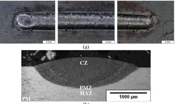
Using process parameters that were optimized on a 3-mm thick IN718 substrate in the STed condition, the characteristics of an ADed single bead from the top surface (Figure 1a) reveal a silver-colored crown surface, which indicates adequate shielding protection during laser deposition and cooling. From the transverse cross-section (Figure 1b), the wide and shallow morphology of the single bead is indicative of laser deposition operated in conduction mode. The dilution ratio (i.e. melted area in the substrate/total melted area) is approximately 60%, which suggests a relatively low heat efficiency. As shown in Figure 1b, the clad zone (CZ), the partially melted zone (PMZ), the heat affected zone (HAZ) and the STed IN718 parent material (PM) can be clearly identified. The narrow HAZ is due to the use of a high energy density laser beam with a small spot size and low heat input. No visible pores or cracks were apparent on both the surface and transverse views of the single beads.
(a)
(b)
Figure 1. (a) Surface morphology and (b) transverse cross-section of an ADed single bead clad on 3-mm thick IN718 substrate. The cladding direction is from the right to the left in Figure 1a.
Based on the optimum process conditions identified for depositing single beads, a multi-bead and multi-layer deposit with approximate dimensions of 100 mm × 300 mm × 30 mm was manufactured, as shown in Figure 2. Macroscopic examination of the deposit shows the absence of visible cracks and the presence of some minor micro-porosity, which demonstrates that high integrity free-forms can be successfully built when using optimized laser processing parameters. As observed in the single bead deposit, three distinct regions can be identified, i.e. PM, HAZ (including PMZ) and CZ. The HAZ between the PM and the multi-bead and multi-layer deposit remains relatively narrow (< 1 mm in size) despite the heat accumulation during laser deposition. Deposition defects
Under certain conditions (material or process), some defects can occur as discussed in following sections.
CZ
PMZ PM
Figure 2. A multi-bead and multi-layer deposit on as-serviced IN718 substrate in ADed condition.
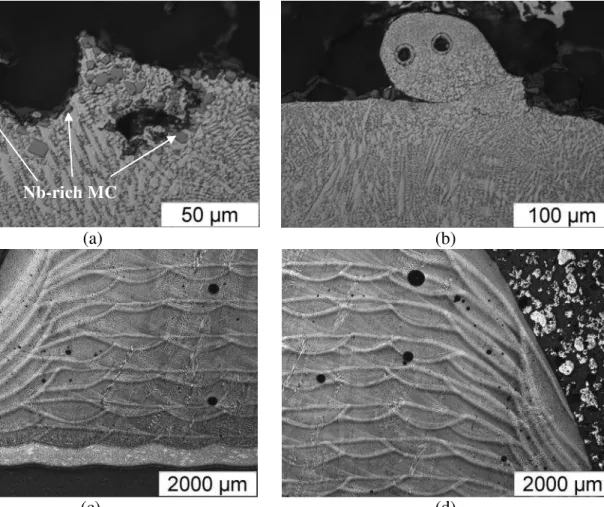
Porosity: As shown in Figure 3, spherical pores can be present in the single bead and multi-bead/multi-layer deposits. The spherical shape of the pores is indicative of their origin. The pores are most likely entrapped gas bubbles in the molten metal bead that could not escape before solidification. In particular, the small gas bubbles in the molten metal can coalesce (forming larger bubbles) as they rise to the top surface (during cladding the escape of the gas porosity before solidification is accessible only by means of the top surface). Hence, if the liquid metal surface solidifies before the gas bubbles have risen and escaped to the top surface, then the gas porosity will be entrapped within the bead. Figure 3a shows two surface pores that had nearly floated to the solidified top surface. As shown in Figure 3b, the presence of hollow spherical pores within a powder particle on the clad surface indicates that the porosity is probably entrapped from the gas atomization process during manufacturing of the powders. Other sources for the formation of gas porosity include the gases for shielding protection and/or any minor contamination from grease, oil and dirt existing on the surfaces of the work-pieces and powder feed materials. Of particular interest also is the significant amount of primary Nb-rich MC carbides and carbonitrides appearing around the surface pores (Figure 3a). The porosity can precipitate on the dry side of the oxide film but the wetted side can favor the nucleation of intermetallics such as Nb-rich MC carbides and carbonitrides, as observed recently in [9]. As a result, both the porosity and intermetallics can float towards the top surface with their shared oxide films and explains the agglomeration and concentration of the intermetallic particles. Un-melted powders: As seen in Figures 3b and 4, some particles (similar in size to the powders applied) may appear on the top surface of the deposited beads. Up to the melting conditions, these particles may have good metallurgical bonding or lack of bonding (LOB) with the deposited metal. On occasion, these particles may also result from spattering. In laser welding, spattering occurs due to the significant vaporization of the material at the high laser power density that causes expulsion or ejection of the liquid metal on account of the large recoil force on the molten pool surface. During conduction-mode laser deposition, a large laser beam size is
PM HAZ PMZ
CZ
used and thus the laser power density is relatively low. Regardless, spattering may occur occasionally due to significant expansion of the gases entrained in the powders.
(a) (b)
(c) (d)
Figure 3. Porosity defects observed in (a-b) single beads and (c-d) multi-bead and multi-layer deposits in ADed conditions.
Figure 4. Un-melted powders from single beads.
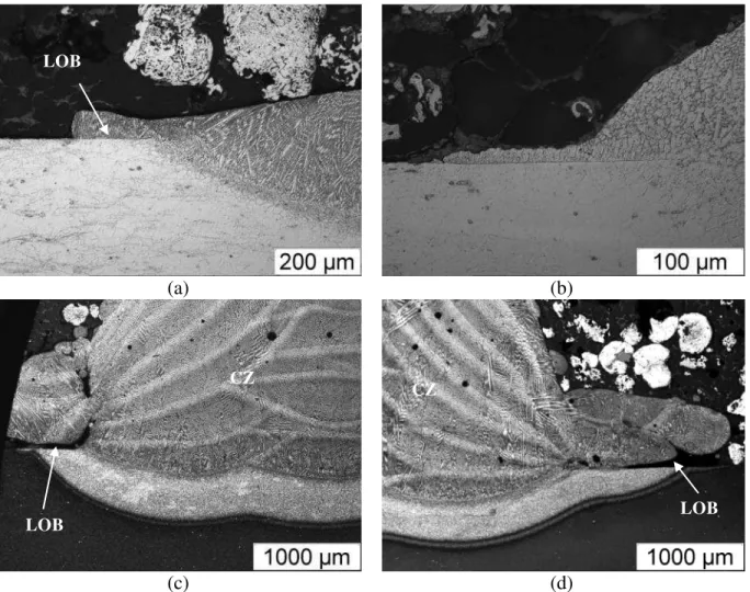
Overlap: Figure 5 shows typical overlap defects, which in turn may exhibit LOB between the deposit and the IN718 substrate or the previously deposited bead. On occasion, the LOB defect was observed to extend into the CZ (e.g. periphery of CZ in Figure 5d). In addition, the occurrence of overlaps significantly increased the crown area and width of the top bead. The surface overlaps also influence the bead shape and, as a result, the morphology of the multi-bead
and multi-layer deposits, such that the overall geometry of the freeform may be indefinite, as shown in Figures 5c-d.
(a) (b)
(c) (d)
Figure 5. Overlap and lack of bonding defects in (a-b) single beads and (c-d) multi-bead and multi-layer deposits.
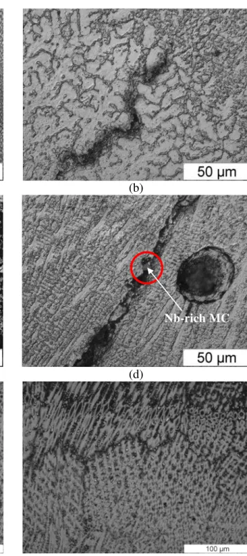
Weld metal liquation cracking: As shown in Figure 6, some interlayer microcracks are frequently present in the lower beads near the layer interface in the ADed condition. These regions in the lower beads act as the HAZ of the adjacent upper layer (beads) deposited later. Therefore, these microcracks are quite similar to the HAZ microfissures or liquation cracks as widely encountered in IN718 welds and are usually termed as weld metal liquation cracking in multi-pass welding [1, 10]. As shown in Figure 6, weld metal liquation cracking occurs in the lower beads near the interfacial area, but the cracks can propagate along the bead interface and even extend into the upper newly deposited beads. Of interest also is the association of the weld metal liquation microcracks with the porosity (Figure 7c) or Nb-rich MC type primary carbides (Figure 7d). The presence of the liquation cracks can be reasoned on the basis of the cast structure in the CZ and the formation of both the Nb-rich carbides and Laves phase during the final stages of solidification. For cast IN718, it is known that liquation cracking is dominated by the melting of the Laves phase rather than constitutional liquation of the Nb-rich carbides, since the former precipitates at a lower temperature [1] and the latter is much lower in amount. Hence, when an
LOB
LOB LOB
CZ
earlier deposited bead is reheated during cladding of a subsequent pass, the solidification grain boundaries in the lower beads adjacent to the layer interface may re-melt and thus form liquated boundaries. The reheating may also promote grain growth, resulting in the formation of migrated grain boundaries along which liquation and even cracking can occur [1].
(a) (b)
(c) (d)
(e) (f)
Figure 6. Weld metal liquation cracking in a multi-bead and multi-layer deposit on an as-serviced IN718 substrate in (a-d) ADed and (e-f) PCHTed conditions.
After PCHTed, the weld metal liquation cracks can be healed (Figures 6e-f) probably due to (i) the lower amount of Laves phase present in the CZ microstructure due to its partial dissolution during the heating stage of the solution heat treatment, (ii) the improved strength of the CZ microstructure due to the release of Nb into the matrix caused by the partial dissolution of the Laves phase during the heating stage and the precipitation of the γ'' strengthening phase during cooling after solution heat treatment, and (iii) release of the thermal strains and shrinkage stresses (associated with rapid solidification after laser deposition) during solution heat treatment [1, 10].
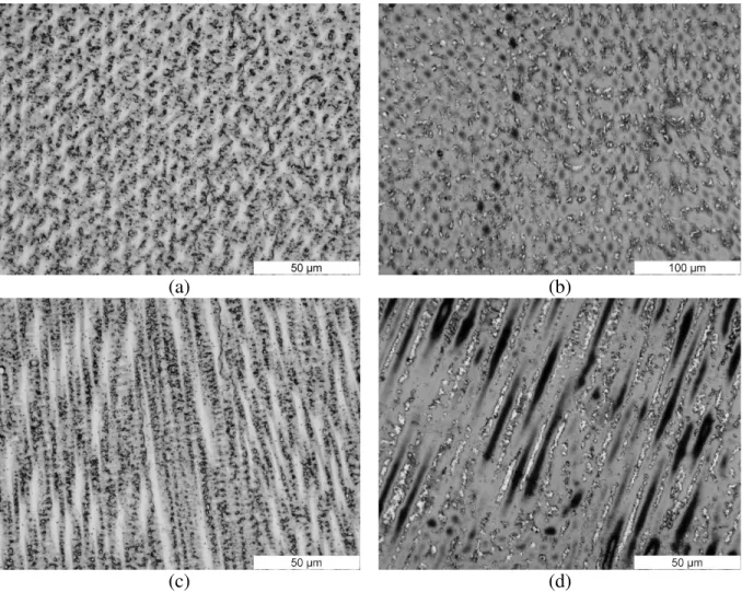
Microstructures
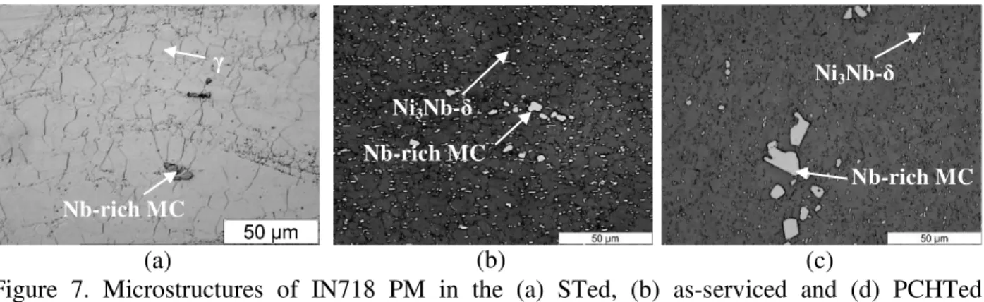
Figure 7 shows the microstructures of the IN718 substrate materials. For the 3-mm thick IN718 sheets, used in solution heat treated condition for the deposition of the single beads (Fig. 1), the microstructure mainly consisted of equiaxed austenitic γ grains decorated with some needle-like δ phase, Nb-rich MC type primary carbides and carbonitrides (Figure 7a). Specifically, the continuous matrix of γ grains is an fcc Ni-based austenitic phase with a high percentage of solid-solution elements such as Co, Cr, Fe, Mo, Nb, Al, Si, Ti and Mn. The needle-like Ni3Nb-δ particles are then mainly precipitated at the grain boundaries of the austenitic γ
matrix. The as-serviced IN718 (that was STAed before service) consisted mainly of equiaxed austenitic γ grains, globular Ni3Nb-δ precipitates at the grain boundaries or the interior of the
grains and Nb-rich MC particles, as well as some age-hardening/strengthening γ' and γ'' phases (that are not apparent in the optical image shown in Figure 7b). Compared to the as-serviced IN718, slight coarsening of the austenitic γ grains is observed after PCHT that can be attributed to the additional solution heat treatment applied (Figure 7c). It is noteworthy that the re-aging heat treatment may also cause coarsening or re-precipitation of the strengthening phases such as γ' and γ'' in the grain interior of the γ matrix; due to the γ/γ' eutectic reaction, γ' can also form in the interdendritic or intergranular regions [1].
(a) (b) (c)
Figure 7. Microstructures of IN718 PM in the (a) STed, (b) as-serviced and (d) PCHTed conditions.
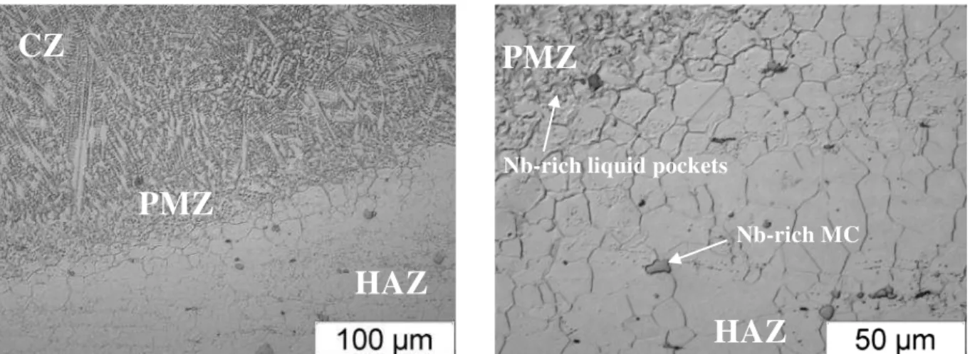
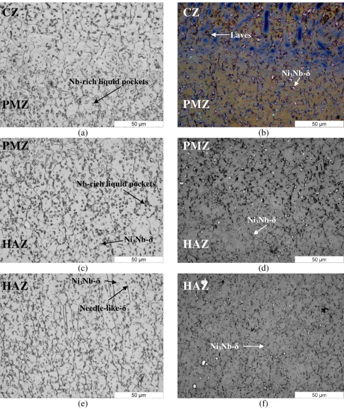
In contrast the microstructures observed in the HAZ between the PM and CZ are more complicated (Figures 8-9) than those in the IN718 substrate materials. In particular, the HAZ was narrow and exhibited no significant grain growth relative to the IN718 PM in the STed condition. Compared to the single beads deposited on STed IN718, the multi-bead and multi-layer deposits, which were clad on the as-serviced IN718, showed HAZ microstructures that evolved (Figure 9) with increasing temperature towards the CZ, as experienced during laser deposition. Specifically, the HAZ near the PM was similar in microstructure to the as-serviced IN718, consisting of the γ
Ni3Nb-δ Nb-rich MC γ Nb-rich MC Ni3Nb-δ Nb-rich MC
matrix, δ-phase (globular and needle), Nb-rich MC type primary carbides and carbonitrides, as well as γ' and γ''. The PMZ in the HAZ close to the CZ (Figures 9a and c) contained some liquid “pockets”, as a result of Ni3Nb-δ phase dissolution during the heating stage of the laser
deposition process that renders relatively high temperatures [10, 11].
Figure 8. HAZ Microstructure taken from a single bead clad on STed IN718in ADed condition. In the PCHTed condition, the fraction of needle-like Ni3Nb-δ precipitates observed in the
PMZ close to the CZ is high (Figure 9b) and their precipitation most likely occurred from the liquid “particle” formed during solution heat treatment (Figures 9b and d). As the solution heat treatment was performed at 954°C, which is lower than the solidus temperature of the Ni3Nb-δ
precipitates, the thermal conditions were insufficient for complete dissolution of the globular Ni3Nb-δ particles in the HAZ. Thus after PCHT, the HAZ near the PM (Figure 5f) has a similar
microstructure to the IN718 (as-serviced or PCHTed), consisting of the γ matrix, globular Ni3Nb-δ, Nb-rich MC type primary carbides, as well as γ' and γ''.
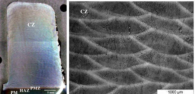
In the CZ, fine dendritic structures are apparent (Figure 10) and are expected on the basis of the heavily alloyed composition of IN718 as well as the relatively rapid cooling rate after laser deposition. Also, these dendrites in the CZ were finer and more equiaxed in the bead center relative to those near the layer interface. That is, the columnar dendritic growth adjacent to the weld bead or the layer interfaces results in fewer, coarser and interconnected Laves particles. In contrast, within the interior of the bead, the fine equiaxed dendritic growth renders small well-separated interdendritic regions that lead to the formation of relatively fine discrete Laves particles [12]. In laser deposition, the relatively rapid cooling rate can also extend solute solubility, which reduces the extent of segregation. During solidification, the elements Nb, Ti and Mo accumulate at the front of the liquid/solid interface and segregate to interdendritic areas, leading to the formation of carbide and Laves particles; however, the γ and NbC eutectic is suppressed during rapid cooling [3, 12].
HAZ
PMZ
Nb-rich liquid pockets
Nb-rich MC
PMZ
HAZ
CZ
(a) (b)
(c) (d)
(e) (f)
Figure 9. Microstructures of the HAZ between the PM (as-serviced) and the CZ of a multi-bead and multi-layer deposit in (a, c, e) ADed and (b, d, f) PCHTed conditions.
Nb-rich liquid pockets
PMZ
CZ
PMZ
CZ
Ni3Nb-δ LavesPMZ
HAZ
HAZ
PMZ
Ni3Nb-δNb-rich liquid pockets
Ni3Nb-δ
HAZ
Needle-like-δ i δ Ni3Nb-δ Ni3Nb-δHAZ
(a) (b)
(c) (d)
Figure 10. Microstructure of the CZ in (a, c) ADed and (b, d) PCHTed conditions; fine discrete Laves particles are observed at the CZ center (a, c) while slightly coarser and interconnected Laves particles are apparent near the layer boundary (c, d).
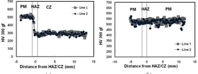
Hardness
The Vickers hardness profiles from the PM to the CZ were measured for a multi-bead and multi-layer deposit on the as-serviced IN718 in both the ADed and PCHTed conditions (Figure 11 and Table I). The hardness of the CZ was about 291 HV in the ADed and 490 HV in the PCHTed conditions. The lower hardness of the CZ in the ADed condition can be related to the thermal cycling that occurs during laser deposition that may dissolve the principal strengthening phase γ'', which has a dissolution temperature around 900°C. Full heat treatment of the deposit can cause precipitation of the γ' and γ'' strengthening phases and thus allow nearly complete recovery of the hardness, as demonstrated in the PCHTed condition. The as-serviced IN718 substrate was fully heat treated before service and hence the PM region has a high average hardness of ~507 HV in the ADed condition, and no significant variation was measured after PCHT (502 HV).
As mentioned above, the hardness difference observed in the CZ in the ADed and PCHTed conditions mainly reflects the γ'' phase fraction precipitated in the microstructure. As the Laves phase present in the CZ microstructure of the deposits in the ADed condition consumes much of the Nb, a relatively low amount of Nb is available for γ'' precipitation. In
addition, the precipitation of the strengthening phases is hindered during laser deposition due to the relatively rapid thermal cycle. Hence, the application of a PCHT [12] is needed to release Nb into the γ matrix by dissolving the Laves phase particles during solution heat treatment; this released Nb is then available for γ'' precipitation during aging. Nonetheless, the amount of Nb available in the CZ for γ'' precipitation in the PCHTed condition is lower than that in the PM, due to the partial dissolution of the Nb-rich Laves phase and the associated formation of δ precipitates. Moreover, the newly formed δ phase is also incoherent with the matrix and thus contributes little to the strengthening effect. As a consequence, the relative hardness in the CZ after PCHT remains slightly (3%) below that of the PM (Table I).
(a) (b)
Figure 11. Vickers microindentation hardness profiles in (a) ADed and (b) PCHTed conditions using as-serviced IN718 substrates.
Table I. Microindentation hardness
Conditions HV 300 gf, 15 s
CZ HAZ in PM PM (IN718) ADed condition on as-serviced IN718 substrate 291.1 ± 18.1 358.4 ± 93.8 506.8 ± 12.5 PCHTed condition on as-serviced IN718 substrate 490.1 ± 18.0 495.8 ± 9.4 502.1 ± 13.6
Conclusions
The macrostructure, defects, microstructure and hardness of the laser deposits using IN718 powders were evaluated in the as-deposited and post-clad heat treated conditions. Depending on the process conditions, some defects such as porosity, un-melted powder, overlap, lack of bonding and weld metal liquation cracking occurred in the deposits. The relatively high cooling rate after laser deposition rendered a clad zone microstructure mainly consisting of a fine dendritic structure with discrete Laves particles. Post-clad solution heat treatment at 954°C caused partial dissolution of the Laves particles and precipitation of the needle-like δ phase around the Laves particles. Ageing after the solution heat treatment, which enabled re-precipitation of the strengthening phases (γ' and γ''), led to near full recovery of the hardness in the laser deposits. Moreover, in the multi-bead multi-layer deposits, the observed weld metal liquation cracks in the as-deposited condition were healed after post-clad heat treatment.
Acknowledgements
The authors are grateful to X. Pelletier and E. Poirier for the preparation of the laser deposited coupons and technical support for metallographic preparation of the coupons.
References
1. J.N. Dupont, J.C. Lippold and S.D. Kiser, Welding Metallurgy and Weldability of Nickel-Base
Alloys (Hoboken, NJ: John Wiley and Sons Inc., 2009).
2. D. Cornu et al., “Weldability of Superalloys by Nd:YAG Laser”, Welding International, 9 (10) (1995), 802-811.
3. X. Cao et al., “Effect of Pre- and Post-weld Heat Treatment on Metallurgical and Tensile Properties of Inconel 718 Alloy Butt Joints Welded Using 4 kW Nd:YAG Laser”, Journal of
Materials Science, 44 (17) (2009), 4557-4571.
4. C.T. Sims, N.S. Stoloff and W.C Hagel, Superalloys II (New York, NY: John Wiley and Sons Inc., 1987), 420-426.
5. H. Qi, M. Azer and A. Ritter, “Studies of Standard Heat Treatment Effects on Microstructure and Mechanical Properties of Laser Net Shape Manufactured Inconel 718”, Metallurgical and
Materials Transactions A, 40 (2009), 2410-2422.
6. B. Baufeld, “Mechanical Properties of Inconel 718 Parts Manufactured by Shaped Metal Deposition (SMD)”, Journal of Materials Engineering and Performance, 21 (7) (2011), 1416-1421.
7. J.C. Ion, Laser Processing of Engineering Materials; Principles, Procedure and Industrial
Application (Oxford, UK: Elsevier Butterworth-Heinemann, 2005).
8. J.D. Kim and Y. Peng, “Plunging method for Nd:YAG laser cladding with wire feeding”,
Optics and Lasers in Engineering, 33 (2000), 299-309.
9. Y.N. Zhang et al., “Oxide Films in Laser Additive Manufactured Inconel 718”, Acta
materialia, submitted, 2013.
10. Y.N. Zhang, X. Cao and P. Wanjara, “Fiber Laser Deposition of Inconel 718 Using Filler Wire”, Journal of Advanced Manufacturing Technology, accepted, 2013.
11. J.W. Hooijmans, J.C. Lippold and W. Lin, “Effect of Multiple Postweld Heat Treatment on the Weldability of Alloy 718”, Superalloys 718, 625, 706 and Various Derivatives, ed. E.A. Loria, (Warrendale, PA: The Minerals, Metals & Materials Society, 1997), 721-730.
12. G.D.J. Ram et al., “Microstructure and Tensile Properties of Inconel 718 Pulsed Nd-YAG Laser Welds”, Journal of Materials Processing Technology, 167 (2005), 73-82.