ASSESSMENT OF FRP-CONFINED CONCRETE: UNDERSTANDING BEHAVIOR AND ISSUES IN NONDESTRUCTIVE EVALUATION USING RADAR
by
Jose Alberto Ortega
B.S., Civil Engineering Texas A&M University (2002)
Submitted to the Department of Civil and Environmental Engineering in Partial Fulfillment of the Requirements for the Degree of
MASTER OF SCIENCE IN CIVIL AND ENVIRONMENTAL ENGINEERING at the
MASSACHUSETTS INSTITUTE OF TECHNOLOGY February 2006
© 2006 Massachusetts Institute of Technology All rights reserved
Signature of Author
Certified by
Accepted by
Department of Civil and Environnenta Engineering ary 20, 2006
Oral Biiyiik6ztiirk Professor of Civil and Environmental Engineering I a a Thesis Supervisor
Andrew J. Whittle Professor of Civil and Environmental Engineering Chairman, Departmental Committee on Graduate Studies
MASSACHUSETTS INS7iTUTE OF TECHNOLOGY
BARKER
Assessment of FRP-Confined Concrete: Understanding Behavior and Issues in Non-destructive Evaluation using Radar
by
Jose Alberto Ortega
Submitted to the Department of Civil and Environmental Engineering on January 20, 2006 in Partial Fulfillment of the Requirements for the Degree of
Master of Science in Civil and Environmental Engineering ABSTRACT
Increase in the use of fiber-reinforced polymer (FRP) composite materials for strengthening and retrofitting of concrete columns and bridge piers has urged the development of an effective non-destructive evaluation (NDE) methodology. Radar technologies have shown great potential for assessing the structural and material integrity of FRP-confined concrete systems. In developing such technology, an interdisciplinary approach must be pursued by integrating contributions of various engineering fields. Under this framework, this thesis aims at establishing fundamental knowledge in two particular research areas: the mechanics and damage behavior of FRP-confined concrete and the characterization of electromagnetic (EM) properties for concrete and FRP materials. Research on mechanics and damage behavior of FRP-confined concrete involved a thorough literature survey on the state-of-the-art understanding of the subject and the execution of an experimental program for load-deformation characterization of FRP-confined concrete cylindrical specimens subjected to monotonic axial compressive loads. Based on the experimental results and comparative studies with recent analytical models, the experimental program was extended to the characterization of specific damage levels using a volumetric deformation metric. Visual inspection of the concrete core of specimens previously loaded to levels close to ultimate failure revealed the existence of significant residual volumetric strains, which upon the removal of the FRP jacket could provoke severe concrete cracking and catastrophic failure. Research on dielectric property characterization of concrete and FRP materials led to the development of an integrated methodology for estimating the complex permittivity of low-loss materials in general using free-space measurements of EM wave transmission. Such development required theoretical modeling of EM wave propagation through dielectric media and experimental measurements of transmission coefficients. Validation studies were performed using Teflon, Lexan, and Bakelite materials whose dielectric properties are established in literature. The methodology was then applied to concrete and FRP materials. Establishing minimum criteria for specimen dimensions and optimal frequency bandwidths is still required before the proposed methodology can be used in field applications. Additionally, exploratory research on the assessment of FRP-confined concrete using radar technologies was conducted. Preliminary results indicate potential of such technologies for detecting features related to the presence of rebar, air cavities, delaminations, and mechanical damage in FRP-confined concrete columns.
Thesis Supervisor: Oral Buyuk6zturk
ACKNOWLEDGMENTS
I would like to express my most sincere gratitude and appreciation to my advisor, Prof. Oral Buyuk6zturk, for his guidance, encouragement, and patience throughout the completion of my SM education and thesis work. Not only have I been part of his work group and conducted valuable research, but I have also learned from him many valuable scholarly skills.
I am thankful to the National Science Foundation (Grant CMS-0324607) and MIT
-Lincoln Laboratory Advanced Concepts Committee (Grant ACC-376) for their financial support to this research. In particular, I am sincerely thankful to Dennis Blejer from MIT
- Lincoln Laboratory for introducing me to the radar aspects of this project. His mentorship, friendship, and valuable comments are greatly appreciated. I also want to thank Tzu-Yang Yu and Alex Eapen for their collaboration with the dielectric property characterization and radar measurement aspects of this thesis. I am also sincerely thankful to Prof. J. Bryan Evans, postdoctoral student Xiaohui Xiao, and graduate student Nicholas Austin from the Department of Earth, Atmospheric, and Planetary Sciences for their mentorship and collaboration with the visual and microscopic observation studies of the internal structure of FRP-confined concrete specimens.
Gratitude is extended to Fyfe Co. LLC for kindly providing the FRP materials for conducting this research. In particular, I would like to thank Mr. Scott Arnold for his valuable comments and guidance regarding the preparation of FRP materials. I would like to also thank Mr. Stephen W. Rudolph for his constant support with laboratory work and his resourcefulness for tackling experimental research issues. My sincere appreciation is extended to all my superb UROP students: Cody Edwards, Joseph O'Connor, LaToya McKinley, Carrie McDonough, and Hillary Dyer, who collaborated with me throughout the development of this research. Special thanks are given to Cody for all his hard work and creativity, and to LaToya for entrusting me part of her summer research experience at MIT.
I would like to wholeheartedly thank all of my co-workers in the research group: Dr. Oguz Gunes, Dr. Ching Au, Dr. Erdem Karaca, and Tzu-Yang Yu. I would not be living this amazing experience at MIT to its fullest without their friendship, encouragement, and wisdom. I cherish every moment, activity, and experience that I have shared with all and
each of them.
And of course, I want to thank all of those whose love makes the difference in my life. To my parents, Alberto and Magdalena, and brothers, Andres and Ernesto, for being the light, joy, and fuel of my existence. To my wonderful and sweet girlfriend, Carenina, for being my constant inspiration and support. To my best friends, KC and Eduardo, for
TABLE OF CONTENTS
Chapter 1 Introduction ...
21
1.1 Damage in FRP-Confined Concrete Systems... 21
1.2 Integrity Assessment of FRP-Confined Concrete... 22
1.3 Interdisciplinary Approach for Developing a Radar NDE Methodology for FRP-C onfined FRP-C oncrete ... 22
1.4 R esearch O bjective ... 23
1.5 R esearch A pproach ... 24
1.5.1 Mechanics and Damage Behavior Characterization Studies ... 24
1.5.2 Characterization of Electromagnetic Properties ... 25
1.5.3 ISAR Radar Measurements... 26
1.6 T hesis O rganization ... 26
Chapter 2 FRP Composites in Infrastructure Rehabilitation:
Applications and Non-Destructive Evaluation...
29
2.1 Overview of FRP Composite Materials... 29
2.2 Constituent Materials in FRP Composites... 30
2.2.1 Fiber Reinforcements... 30
G lass F ibers... . 30
C arbon Fibers... . 31
A ram id Fibers ... . 31
2.2.2 Forms of Fiber Reinforcement... 33
2.2.3 M atrices... . 34
2.2.4 Manufacturing Methods... 35
2.3 Mechanical and Durability Characteristics of FRP Composites... 36
2.3.1 Elastic Modulus ... 37 2.3.2 Strength ... . . 38 2.3.3 Energy Absorption... 38 2.3.4 Impact Resistance ... 38 2.3.5 Thermal Expansion... 39 2.3.6 Fatigue Resistance ... 39 2.3.7 Environmental Durability ... 40
2.4 Structural Strengthening and Retrofitting of Reinforced Concrete Structures ... 41
2.4.1 Rehabilitation Needs of Existing Infrastructures... 41
2.4.2 State-of-the-Art in Developments and Applications of FRP Composites ... 42
2.4.3 Applications of FRP Composites for Strengthening and Retrofitting of Concrete Column Members... 44
Design Example for Calculating the Increase of Concrete Compressive Strength based on FRP Wrapping... 45
2.5 Non-Destructive Evaluation of FRP Retrofitted Concrete Structures... 46
2.5.1 Challenges in NDE of FRP-Confined Concrete Structures ... 47
2.5.2 NDE Technologies for Civil Infrastructure ... 48
2.5.3 NDE Methods Applied to FRP-Confined Concrete Systems ... 51
Infrared Thermography... 51
D isadvantage... . 52
A dvantages... 54
Disadvantages ... 54
Radar M icrow ave - Zoughi and Bakhtiari (1990) ... 55
A dvantages... 55
Disadvantages ... 55
Radar M icrow ave - Feng et al. (2002) ... 55
A dvantage ... 56
Disadvantages ... 56
2.5.4 Radar Microwave - APS-CW Technique for NDE of FRP-Confined Concrete Colum ns... 57
Chapter 3 Mechanics and Damage Behavior in FRP-Confined
C oncrete ...
59
3.1 M ulti-Axial Stress States in Concrete... 60
3.1.1 Modeling Concrete under Multi-Axial Compression ... 60
3.1.2 Nonlinear Stress-Strain Behavior for Uniaxial and Triaxial Compressive Stress States ... 61
3.1.3 Active and Passive Confinem ent in Concrete... 63
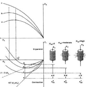
3.1.4 Deformation Behavior and Damage Characterization of Concrete under M ulti-Axial Stress States ... 65
3.2 Concrete Confined w ith FRP Com posite M aterials... 67
3.2.1 Confinement Mechanics of Circular Column Elements ... 67
3.2.2 Stress-Strain Response... 68
3.2.3 Failure M odes of FRP-Confined Concrete ... 70
3.3 Review on Damage Evolution of FRP-Confined Concrete ... 71
3.3.1 Bi-Linear Behavior of FRP-Confined Concrete and Mechanisms of Confinem ent... 71
3.3.2 Kinking Point... 72
3.3.3 Localized Dam age ... 72
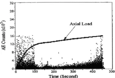
3.3.4 Monitoring of Damage Evolution using Acoustic Emission Techniques.... 73
3.4 Experimental Studies on Characterization of Mechanical Behavior of FRP-Confined Concrete ... 75
3.4.1 Objective and Overview ... 75
Test M atrix... 75 Sign Conventions... 76 Units... 76 3.4.2 M aterial Selection... 76 Concrete ... 76 Capping M aterial ... 77 Cylinder M olds ... 77 FRP Com posites ... 78 3.4.3 Specim ens ... 79 Cylinder Configuration... 79 FRP W rapping Configuration... 81
Concrete Casting Procedures... 81
FRP Com posite System Installation ... 82
3.4.5 L oading ... . . 84
3.5 Experimental Results of Mechanical Behavior of FRP-Confined Concrete ... 86
3.5.1 Load-Deformation Behavior... 86
3.5.2 Maximum Stresses and Strains ... 89
3.5.3 Differential Shortening Behavior... 90
3.5.4 Analysis of Mechanical Behavior... 91
3.6 Analytical Modeling of Mechanical Behavior of FRP-Confined Concrete... 93
3.6.1 State-of-the-Art in Stress-Strain Modeling... 93
Sam aan et al. 1998 ... . 94
Spoelstra and Monti 1999 ... 95
Lam and T eng 2003 ... 98
3.6.2 Performance of Existing Models and Comparison with Experimental Data99 3.7 Characterization of Damage Stages in FRP-Confined Concrete ... 100
5.7.1 T est M atrix ... 102
5.7.2 Load-Deformation Behavior and Conditioning of Specimens ... 103
3.8 Bisection Procedures and Microscopic Observations for Determination of Mechanical Damage in FRP-Confined Concrete... 105
3.8 .1 O bjective ... 105
3.8.2 Background Information on Internal Observations of Concrete... 105
3.8.3 Experimental Procedures ... 106
Bisection of FRP-Confined Concrete Specimens... 106
3.8.4 Results of Bisection Procedures and Optical Microscopic Observations.. 108
Observations during Bisection Procedures... 108
Observations using Optical Microscopy... 109
3.8.5 C onclusions... 109
Chapter 4 Electromagnetic Properties of Concrete and FRP
Composite M aterials...
113
4.1 Fundamentals of Electromagnetic Wave Theory... 113
4.1.1 Maxwell's Equations and Constitutive Relationships ... 115
4.1.2 Definitions of Electromagnetic Properties... 117
D ielectric C onstant... 117
L oss F actor... 117
4.1.3 Significance of Electromagnetic Properties in Microwave Propagation, Scattering, and N D E ... 118
Velocity and Wavelength of Microwaves inside Dielectric Media... 119
Attenuation and Penetration Depth... 120
4.2 Characterization of Dielectric Properties of Concrete and FRP Materials... 121
4.2.1 State-of-the-Art for Dielectric Property Characterization ... 121
Capacitor Model - Parallel Plate Capacitor Technique... 121
Resonator/Oscillator Model - Resonant Cavity Technique... 121
Transmission Line Model - Open-Ended Coaxial Probe Technique ... 121
Transmission Line Model - Rectangular Waveguide Technique... 122
Free-Space T echnique... 122
4.3 Development of Integrated Methodology for Determining Dielectric Properties of Concrete and FRP Materials... 123
4.3.2 Theoretical Representation of Transmission Coefficient ... 124
4.3.3 Estimation Procedure based on Time Difference of Arrival (TDOA)... 126
4.3.4 Root-Searching Procedure of Combinations of Dielectric Constant and Loss Factor based on Param etric SI and SSE Criterion ... 128
4.4 Experimental Program for Dielectric Property Measurements... 133
4.4.1 Sam ple Description... 133
4.4.2 Experimental Configuration and Measurement Parameters ... 134
4.5 Experimental Results and Characterization of Dielectric Properties... 138
4.5.1 M easurements of Transm ission Coefficients... 138
4.5.2 Estim ation of the Dielectric Constant using TDOA ... 139
4.5.3 Root-Searching Results for Loss Factor ... 140
4.6 Discussion of Results... 142
4.6.1 Effect of Selected Frequency Bands in TDOA ... 143
4.6.2 Lim itations of the Use of TDOA Information ... 143
Chapter 5 Radar Measurements of FRP-Confined Concrete... 147
5.1 Fundam entals of Radar ... 147
5.1.1 Radar Parameters ... 149
Pulse W idth and Bandwidth... 149
Range and Cross-Range Resolutions... 149
Polarization ... 150
Decibel (dB)... 151
Radar Cross Section (RCS)... 152
Near Field and Far Field ... 152
Coherent Radar ... 153
5.1.2 Inverse Synthetic Aperture Radar (ISAR)... 153
5.2 Important Issues related to ISAR Test Parameters ... 154
5.2.1 Penetration Depth vs. Frequency ... 155
5.2.2 Bandwidth and Rotation Angle vs. Computational Cost... 156
5.3 Signal Processing... 158
5.3.1 Fourier Transform M ethod ... 158
5.3.2 Cross-Correlation... 159
5.3.3 Backprojection Im aging Algorithm ... 159
5.4 Radar M easurem ents of FRP-Confined Concrete... 160
5.4.1 Radar M easurem ent Set-up... 160
5.4.2 Experiment Param eters... 162
M easurement Schem es... 162
Radar Parameters ... 162
5.4.3 Test Program ... 165
5.4.4 Data Processing... 168
5.5 Results of Radar M easurem ents... 169
5.5.1 Frequency - Angle Imagery... 169
5.5.2 Cross-Correlation Studies... 175
5.5.3 Range - Angle Im agery ... 177
5.5.4 ISAR Im agery ... 181
5.6 Discussion of Results... 185
M easurement Schemes... 185
X- and Ku-Bands ... 186
Polarization ... 186
5.6.2 Feature Detection... 187
Cavities and Delaminations ... 187
Deform ation / M icrocracking ... 187
R eb ar ... 18 7 5.6.3 Evaluation of Data Interpretation Techniques ... 188
Frequency - Angle, Range - Angle, and ISAR Im agery... 188
Cross-Correlation... 188
Chapter 6 Summary, Conclusions, and Future Work... 191
6.1 Sum m ary ... 191
6.2 Conclusions... 193
6.2.1 Mechanics and Damage Behavior of FRP-Confined Concrete ... 193
6.2.2 Characterization of Dielectric Properties... 194
6.2.3 Radar M easurements of FRP-Confined Concrete... 195
6.3 Future W ork ... 195
R eferences... 197
A ppendix A ...
207
Frequency - Angle Im agery for All M easured Specim ens... 207
A ppendix B ... 227
LIST OF FIGURES
Figure 1-1 Interdisciplinary approach for developing a robust radar NDE methodology23 Figure 1-2 Research O bjectives ... 24 Figure 2-1 Different types of FRP composites based on fiber length and orientation (Hull and C lyne 1996)... . . 33 Figure 2-2 Schematics of basic fiber forms (a) single fiber, (b) strand or two, (c)
filament yarn, (d) roving (Gunes 2004) ... 34 Figure 2-3 Examples of manufacturing methods (Gunes 2004)... 36 Figure 2-4 Voigt and Reuss bounds of laminate stiffness (a) elastic modulus in
longitudinal direction, (b) elastic modulus in transverse direction, (c) laminate stiffness as function of loading direction and fiber volume fraction ... 37 Figure 2-5 Typical S-N curves for unidirectional composites (Holloway 1993) ... 39 Figure 2-6 Development of damage and stiffness reduction in a 00/900 GFRP laminate
(H ollow ay 1993) ... 40 Figure 2-7 Use of FRP composites in civil infrastructure (Van Den Einde et a]. 2003) 42 Figure 2-8 Methods of beam strengthening in flexure with FRP composite (Gunes 2004)
... 4 3 Figure 2-9 Failure mechanisms in FRP-confined concrete (Au 2001)... 47 Figure 2-10 Tomography image of a hollow concrete cylinder and one-dimensional
profile of attenuation coefficient along a white line (Martz et al. 1991)... 49 Figure 2-11 A computer-enhanced tomogram of a wall in a building under repair
(Stanley and Balendran 1994)... 50 Figure 2-12 Typical variation on AE counts during compression (Mirmiran et a]. 1999)
... 5 3 Figure 2-13 Effect of jacket thickness on cumulative AE counts (Mirmiran eta]. 1999)53 Figure 2-14 Effect of column size and jacket thickness on AE counts (Mirmiran et aL.
19 9 9) ... 5 3 Figure 2-15 (a) Schematic of numerical modeling, (b) Results of scanned image of a void caused by a hole in the concrete surface (Feng et aL. 2002). ... 56 Figure 2-16 Schematic of the APS-CW technique ... 57 Figure 3-1 (a) Load transfer in a particle stack scenario (b) Particle interactions under
biaxial compression (van M ier 1997) ... 60 Figure 3-2 Typical stress-strain curves for uniaxial compression ... 62 Figure 3-3 Stress-strain curves under multi-axial compression (Palaniswamy and Shah
19 7 4) ... 6 3 Figure 3-4 Triaxial testing device (Imran and Pantazopoulou 1996) ... 64 Figure 3-5 Geometry of volumetric strain plots for axially loaded concrete subjected to
different levels of confinement (Imran and Pantazopoulou 1996) ... 67 Figure 3-6 Lateral (radial) and hoop stresses present in confining action... 68 Figure 3-7 Stress-strain curves for FRP confined concrete for increasing and decreasing
types (Lam and Teng 2003) ... 69 Figure 3-8 Stress-strain curves for FRP-confined concrete (a) CFRP-wrapped cylinders
(b) GFRP-wrapped cylinders (Lam and Teng 2004) ... 70 Figure 3-9 Kink point in stress-strain response for GFRP-confined concrete under
Figure 3-10 Localized damage zone in FRP-confined concrete (Au 2001) ... 73 Figure 3-11 Typical variation of cumulative AE counts versus axial load (Mirmiran et
a]. 19 9 9 ) ... 7 4 Figure 3-12 FRP composite system installation (a) Mixing of epoxy resin (b) Samples
curing after installation of epoxy jacket... 83 Figure 3-13 D ata acquisition system ... 84 Figure 3-14 LV DT m ounting system ... 85 Figure 3-15 Set-up for instrumentation mounted on a FRP-confined concrete specimen85 Figure 3-16 Baldw in loading fram e... 86 Figure 3-17 Axial stress - axial strain and axial stress - lateral strain curves for
FRP-w rapped concrete specim ens... 87 Figure 3-18 Axial stress - axial strain and axial stress - lateral strain curves for plain
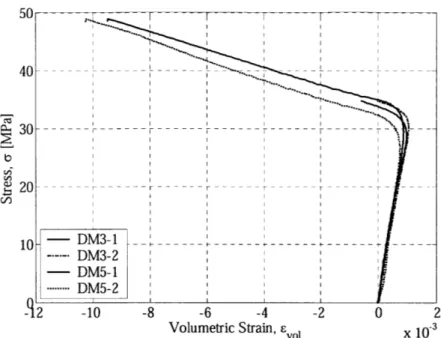
concrete specim ens ... . 87 Figure 3-19 Axial stress - volumetric strain curves for FRP-wrapped concrete specimens ... 88 Figure 3-20 Axial stress - volumetric strain curves for plain concrete specimens ... 88 Figure 3-21 Overlap strengthening on one-ply FRP-wrapped concrete, specimen CCO191 Figure 3-22 Comparison of analytical models with experimental results (a) Normal view (b) Close up to zone of interest ... 100 Figure 3-23 Characterization of deformation stages for FRP-confined concrete
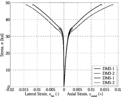
sp ecim en s ... 10 2 Figure 3-24 Axial stress - axial strain and axial stress - lateral strain curves for
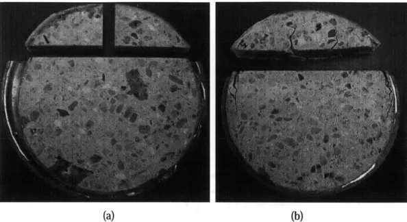
FRP-wrapped concrete specimens conditioned under compressive load... 103 Figure 3-25 Axial stress - volumetric strain curves for FRP-wrapped concrete specimens conditioned under com pressive load... 104 Figure 3-26 Close up of axial stress - volumetric strain curves for FRP-wrapped concrete specimens conditioned under compressive load... 104 Figure 3-27 Photographs of equipment used for bisection of specimens ... 107 Figure 3-28 Examples of specimens after cutting procedure... 107 Figure 3-29 Bisected cross-sections and portions of specimens (a) MD1 and (b) MD5108 Figure 3-30 Optical microscopic images for the concrete matrix of specimen MD5 using
(a) x10 zoom and (2) x 40 zoom ... 110 Figure 4-1 Electric and magnetic field vectors for a uniform plane wave (Staelin et a].
19 9 4) ... 1 15 Figure 4-2 Overview of the proposed methodology for dielectric property
characterization (Buyuk6zturk et a]. 2005) ... 125 Figure 4-3 Two-dimensional model for EM wave transmission analysis ... 125 Figure 4-4 Illustration of theoretical framework for TDOA estimation... 128 Figure 4-5 Experimentally measured transmission coefficient for a concrete slab
sp ecim en ... 130 Figure 4-6 Effect of dielectric constant on predicted transmission coefficient (layer
thickness d, = 50 m m , loss factor Z = 0.0) ... 130 Figure 4-7 Effect of loss factor on predicted transmission coefficient (layer thickness dI = 50 m m , loss factor c = 6.0)... 131
Figure 4-8 Effect of layer thickness on predicted transmission coefficient (dielectric
constant
4
= 6.0, loss factor e = 0.0) ... 131Figure 4-9 Estimation error surface using parametric SI and SSE criterion for concrete slab specimen. Color coding represents log(SSE) ... 132
Figure 4-10 Result of root-searching procedure for identification of loss factor for concrete slab specim en ... 133
Figure 4-11 Experimental set-up for dielectric property measurements a) Network analyzer, b) Transmit horn, c) FRP sample, d) FRP sample and receive horn (Pictures courtesy of Dennis Blejer)... 136
Figure 4-12 Radar measurement schemes for EM wave propagation at 0* and 300 incid en ce ... 137
Figure 4-13 Radar measurements of transmission coefficients ... 139
Figure 4-14 Estimation of time difference of arrival (TDOA) ... 140
Figure 4-15 Estimation error surfaces using parametric SI and SSE criterion... 141
Figure 4-16 Results of root-searching procedure for identification of imaginary part of com plex perm ittivity ... 142
Figure 4-17 Comparative study of different phase velocity representations... 145
Figure 5-1 Block diagram of a typical coherent radar (Sullivan 2000) ... 148
Figure 5-2 Linear frequency modulated pulse waveform... 149
Figure 5-3 Reflection and transmission of a TE or HH-polarized wave in a semi-infinite m ed iu m ... 15 1 Figure 5-3 Spotlight SAR (W ehner 1995)... 154
Figure 5-4 Dielectric constant, loss factor, and conductivity for concrete at X- and Ku-band frequencies (Rhim and Buyuk6zturk 1998) ... 157
Figure 5-5 Photographs of the MIT- Lincoln Laboratory Compact RCS/Antenna Range facility, Building 1718: reflector and feed horn antenna (top), and Styrofoam tower (bottom ) (Courtesy of Dennis Blejer) ... 161
Figure 5-6 ISAR measurement schemes (a) sample resting on its end cap, (b) sample resting on its side. ISAR measurement scheme notations (c) normal incidence, (d) oblique incidence ... 163
Figure 5-7 Specimen configurations (all dimensions are in mm) ... 167
Figure 5-8 Photographs of selected specimens... 167
Figure 5-9 Frequency - angle imagery for specimen CYL-RE measured at normal incidence, X -band, VV polarization ... 170
Figure 5-10 Frequency - angle imagery for specimen CYL-AD1 measured at normal incidence, X-band, HH polarization, back surface (no defect)... 171
Figure 5-11 Frequency - angle imagery for specimen CYL-AD 1 measured at normal incidence, X-band, HH polarization, front surface (with defect) ... 171
Figure 5-12 Frequency - angle imagery for specimen CYL-AD 1 measured at oblique incidence, X-band, HH polarization, back surface (no defect)... 172
Figure 5-14 Frequency - angle imagery for specimen CYL-ADI measured at oblique incidence, X-band, HH polarization, front surface (with defect) ... 172
Figure 5-15 Frequency - angle imagery for specimen CYL-AD2 measured at normal incidence, X-band, HH polarization, front surface (with defect) ... 173
Figure 5-16 Frequency - angle imagery for specimen CYL-AD2 measured at oblique incidence, X-band, HH polarization, front surface (with defect) ... 173
Figure 5-17 Frequency - angle imagery for specimen CYL-MD1 measured at normal incidence, X -band, H H polarization ... 174 Figure 5-18 Frequency - angle imagery for specimen CYL-MD3 measured at normal
incidence, X -band, H H polarization ... 174 Figure 5-19 Frequency - angle imagery for specimen CYL-MD5 measured at normal
incidence, X -band, H H polarization... 175 Figure 5-20 Autocorrelation and cross-correlation functions for selected cases: (a) and
(b) for CYL-ADI specimen measured in normal incidence, X-band, HH
polarization, (c) and (d) for CYL-AD1 specimen measured in oblique incidence, X-band, V V polarization ... 176 Figure 5-20 (continued) Autocorrelation and cross-correlation functions for selected
cases: (e), (f), and (g) for CYL-MD series specimens measured in normal incidence, X -band, H H polarization... 177 Figure 5-21 Range - angle imagery for specimen CYL-AD1 measured at normal
incidence, X-band, HH polarization for different incident angles... 179 Figure 5-22 Range - angle imagery for specimen CYL-AD1 measured at oblique
incidence, X-band, HH polarization for different incident angles... 180 Figure 5-23 ISAR imagery for specimen CYL-RE measured at normal incidence,
X-band, HH and VV polarizations at 0 and 90 deg incident angles ... 182 Figure 5-24 ISAR imagery for specimen CYL-AD1 measured at normal incidence,
X-band, HH and VV polarizations, front surface (with defect)... 182 Figure 5-25 ISAR imagery for specimen CYL-ADI measured at oblique incidence,
X-band, HH polarization, back surface (no defect) and front (with defect) at different incident angles ... 183 Figure 5-26 ISAR imagery for specimen CYL-MD1 measured at normal incidence,
X-band, H H and V V polarizations... 184 Figure 5-27 ISAR imagery for specimen CYL-MD5 measured at normal incidence,
X-band, H H and V V polarizations... 184 Figure 5-28. Example of application of change detection and cross-correlation techniques
for detection of defects in FRP-confined confined concrete. For (a) and (b), autocorrelation signal is frequency data for 0,rf = 1600. For (c) and (d), autocorrelation signal is frequency data for 9
,ef = 00. ... 190 Figure A-I Frequency - angle imagery for specimen CYL-ME measured at normal
incidence, X -band, HH polarization ... 208 Figure A-2 Frequency - angle imagery for specimen CYL- ME measured at normal
incidence, X -band, VV polarization ... 208 Figure A-3 Frequency - angle imagery for specimen CYL- ME measured at normal
incidence, K u-band, HH polarization ... 209 Figure A-4 Frequency - angle imagery for specimen CYL- ME measured at normal
incidence, K u-band, VV polarization ... 209 Figure A-5 Frequency - angle imagery for specimen CYL-PC measured at normal
incidence, X -band, H H polarization ... 210 Figure A-6 Frequency - angle imagery for specimen CYL-PC measured at normal
incidence, X -band, V V polarization ... 210 Figure A-7 Frequency - angle imagery for specimen CYL-PC measured at normal
Figure A-8 Frequency - angle imagery for specimen CYL-PC measured at normal incidence, Ku-band, VV polarization ... 211 Figure A-9 Frequency - angle imagery for specimen CYL-CC measured at normal
incidence, X-band, Figure A- 10 Frequency incidence, X-band, Figure A-11 Frequency incidence, X-band, Figure A- 12 Frequency incidence, X-band, Figure A-13 Frequency incidence, X-band, Figure A-14 Frequency incidence, X-band, Figure A-15 Frequency incidence, X-band,
H H polarization ... 212
- angle imagery for specimen CYL-CC measured at normal V V polarization ... 212
- angle imagery for specimen CYL-RE measured at normal H H polarization ... 213
- angle imagery for specimen CYL-RE measured at normal V V polarization ... 214
- angle imagery for specimen CYL-ADI measured at normal HH polarization, back surface (no defect)... 215
- angle imagery for specimen CYL-ADI measured at normal VV polarization, back surface (no defect)... 215
- angle imagery for specimen CYL-ADI measured at normal HH polarization, front surface (with defect) ... 216 Figure A-16 Frequency - angle imagery for specimen CYL-ADI measured at normal
incidence, X-band, VV polarization, front surface (with defect) ... 216 Figure A-17 Frequency - angle imagery for specimen CYL-ADI measured at normal
incidence, Ku-band, HH polarization, back surface (no defect)... 217 Figure A-18 Frequency - angle imagery for specimen CYL-ADI measured at normal
incidence, Ku-band, VV polarization, back surface (no defect)... 217 Figure A-19 Frequency - angle imagery for specimen CYL-ADI measured at normal
incidence, Ku-band, HH polarization, front surface (with defect) ... 218 Figure A-20 Frequency - angle imagery for specimen CYL-ADI measured at normal
incidence, Ku-band, VV polarization, front surface (with defect) ... 218 Figure A-21 Frequency - angle imagery for specimen CYL-AD1 measured at oblique
incidence, X-band, HH polarization, back surface (no defect)... 219 Figure A-22 Frequency - angle imagery for specimen CYL-ADI measured at oblique
incidence, X-band, VV polarization, back surface (no defect)... 219 Figure A-23 Frequency - angle imagery for specimen CYL-ADI measured at oblique
incidence, X-band, HH polarization, front surface (with defect) ... 220 Figure A-24 Frequency - angle imagery for specimen CYL-AD1 measured at oblique
incidence, X-band, VV polarization, front surface (with defect) ... 220 Figure A-25 Frequency - angle imagery for specimen CYL-AD2 measured at normal
incidence, X-band, HH polarization, front surface (with defect) ... 221 Figure A-26 Frequency - angle imagery for specimen CYL-AD2 measured at normal
incidence, X-band, VV polarization, front surface (with defect) ... 221 Figure A-27 Frequency - angle imagery for specimen CYL-AD2 measured at oblique
incidence, X-band, HH polarization, front surface (with defect) ... 222 Figure A-28 Frequency - angle imagery for specimen CYL-AD2 measured at oblique
incidence, X-band, VV polarization, front surface (with defect) ... 222 Figure A-29 Frequency - angle imagery for specimen CYL-AD3 measured at normal
incidence, X -band, HH polarization ... 223 Figure A-30 Frequency - angle imagery for specimen CYL-AD3 measured at normal
Figure A-31 Frequency - angle imagery for specimen CYL-MD1 measured at normal incidence, X -band, H H polarization ... 224 Figure A-32 Frequency - angle imagery for specimen CYL-MD 1 measured at normal
incidence, X -band, V V polarization ... 224 Figure A-33 Frequency - angle imagery for specimen CYL-MD3 measured at normal
incidence, X -band, H H polarization ... 225 Figure A-34 Frequency - angle imagery for specimen CYL-MD3 measured at normal
incidence, X -band, V V polarization ... 225 Figure A-35 Frequency - angle imagery for specimen CYL-MD5 measured at normal
incidence, X -band, H H polarization ... 226 Figure A-36 Frequency - angle imagery for specimen CYL-MD5 measured at normal
incidence, X -band, V V polarization ... 226 Figure B-1 ISAR imagery for specimen CYL-ME measured at normal incidence,
X-band, H H and V V polarizations... 228 Figure B-2 ISAR imagery for specimen CYL- ME measured at normal incidence,
Ku-band, H H and V V polarizations... 228 Figure B-3 ISAR imagery for specimen CYL-PC measured at normal incidence, X-band, H H and V V polarizations... 229 Figure B-4 ISAR imagery for specimen CYL-PC measured at normal incidence,
Ku-band, H H and V V polarizations... 229 Figure B-5 ISAR imagery for specimen CYL-CC measured at normal incidence, X-band, H H and V V polarizations... 230 Figure B-6 ISAR imagery for specimen CYL-RE measured at normal incidence, X-band, HH and VV polarizations at 0 and 90 deg incident angles... 230 Figure B-7 ISAR imagery for specimen CYL-RE measured at normal incidence, X-band, HH and VV polarizations at 180, and 270 deg incident angles... 231 Figure B-8 ISAR imagery for specimen CYL-AD1 measured at normal incidence,
X-band, HH and VV polarizations, back surface (no defect) ... 231 Figure B-9 ISAR imagery for specimen CYL-AD1 measured at normal incidence,
X-band, HH and VV polarizations, front surface (with defect)... 232 Figure B-10 ISAR imagery for specimen CYL-ADI measured at normal incidence,
Ku-band, HH and VV polarizations, back surface (no defect) ... 232 Figure B- 1 ISAR imagery for specimen CYL-ADI measured at normal incidence,
Ku-band, HH and VV polarizations, front surface (with defect)... 233 Figure B-12 ISAR imagery for specimen CYL-ADI measured at oblique incidence,
X-band, HH polarization, back surface (no defect) at different incident angles... 234 Figure B-13 ISAR imagery for specimen CYL-AD1 measured at oblique incidence,
X-band, HH polarization, front surface (with defect) at different incident angles ... 235 Figure B-14 ISAR imagery for specimen CYL-AD2 measured at oblique incidence,
X-band, HH and VV polarizations, front surface (with defect)... 236 Figure B-15 ISAR imagery for specimen CYL-MDI measured at normal incidence,
X-band, H H and V V polarizations... 236 Figure B-16 ISAR imagery for specimen CYL-MD3 measured at normal incidence,
X-band, H H and V V polarizations... 237 Figure B-17 ISAR imagery for specimen CYL-MD5 measured at normal incidence,
LIST OF TABLES
Table 2-1 Typical properties of glass fibers (Tuttle 2004) ... 32
Table 2-2 Typical properties of commercially available carbon fibers (Tuttle 2004)... 32
Table 2-3 Typical properties of Kevlar 49 fibers (Tuttle 2004) ... 32
Table 2-4 Selected properties for different types of polymeric matrices (Hull and Clyne 19 9 6 ) ... 3 5 Table 2-5 Typical mechanical properties of unidirectional laminates (Schwartz 1997) .36 Table 3-1 Test matrix for characterization of mechanical behavior of plain and FRP-w rapped concrete specim ens... 76
Table 3-2 28-day compressive strength values for all concrete batches... 77
Table 3-3 Typical dry fiber properties... 78
Table 3-4 Epoxy material properties... 78
Table 3-5 Composite gross laminate properties... 79
Table 3-6 Maximum stress and strain values for specimens under test... 90
Table 3-7 Input parameters for evaluation of analytical models ... 100
Table 3-8 Test matrix of specimens conditioned through mechanical loading to specific dam age stages ... 103
Table 4-1 Radar frequency band designations (IEEE 1984) ... 114
Table 4-1 Test matrix for dielectric property characterization ... 134
Table 4-2 Dielectric constant estimations based on TDOA for 8-18 GHz... 140
Table 4-3 Characterization of complex permittivity for all test materials... 141
Table 4-4 Estimates for dielectric constant using TDOA for different frequency ranges ... 1 4 3 Table 5-2 Radar measurement test program... 166
Table 5-3 A sample of raw data collected for CYL-AD1... 169
Table 5-4 Summary of cross-correlation studies ... 175
Chapter 1
Introduction
Civil infrastructure is one of the most valuable assets in any country. In the United States, the nation's infrastructure, which was generally built in 1950s, is now approaching the service life, and in need of urgent repair and retrofit. Approximately 27% of the nations' 600,000 bridges were reported to be structurally deficient or functionally obsolete (ASCE 2005). Rehabilitation and upgrading of existing structures are estimated to cost about $212 billion, prompting the urgent need for finding rapid and cost-efficient assessment and repair technologies. In the past decades, the use of fiber-reinforced polymer (FRP) composite materials has experienced substantial growth in structural strengthening and retrofitting applications worldwide. With improved mechanical and durability properties, FRP composite jacketing systems have emerged as an alternative to traditional strengthening and repair of reinforced concrete columns and bridge piers. A large number of civil infrastructure projects from the public and private sectors have opted for FRP technologies. Although substantial research has been conducted in the area of mechanical behavior characterization of FRP-confined concrete column elements, several research issues such as improving the current understanding of damage processes in the concrete core as well as developing reliable non-destructive evaluation techniques for these systems require further investigation.
1.1 Damage in FRP-Confined Concrete Systems
Over the past decade, extensive research has been devoted to the understanding of the mechanical behavior of FRP-confined concrete systems. In particular, the main emphases of such studies have been the investigation of failure modes and ultimate conditions or stages of damage. However, mechanical processes leading to damage or failure of the concrete core are not well understood (Lau and Zhou 2001, Mirmiran and Yunmei 2001).
Furthermore, recent studies have identified that a concrete column could appear safe without showing any visible signs of substantial damage in the FRP jacket and yet containing a damaged concrete core (Au and Buyukozturk 2005). Thus, there is a pressing need for better understanding of the damage extent and evolution phenomena in FRP-confined concrete systems before they can be used widely and reliably.
1.2 Integrity Assessment of FRP-Confined Concrete
Existing evaluation methods for FRP-confined concrete systems such as visual inspection and sample extraction are labor intensive, time consuming, and destructive to structures. Other methods such as acoustic emission would require the continuous monitoring of the structure in order to detect changes in performance or structural integrity. In addition, these methods are unable to provide sufficient information regarding the extent of damage or the presence of defects such as air cavities or FRP/concrete delaminations. Non-destructive evaluation (NDE) methods using radar technologies have the potential for assessing the concrete conditions inside the FRP jacket. The development of an effective radar NDE methodology is needed to match the growing industrial applications of FRP jacketing systems for concrete columns and bridge piers.
1.3 Interdisciplinary Approach for Developing a Radar NDE Methodology for FRP-Confined Concrete
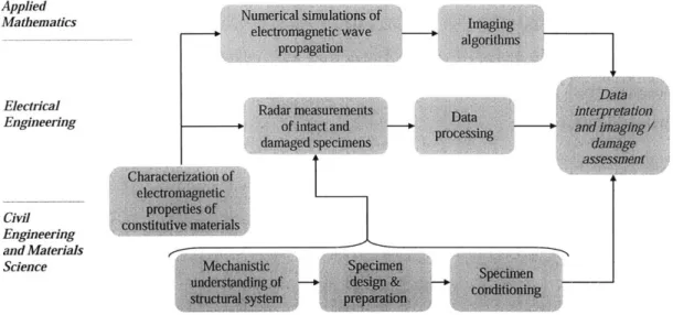
Developing of a robust damage assessment methodology using radar for FRP-confined concrete systems would require synthesizing knowledge being developed in distinct research areas such as structural engineering, materials science, electrical engineering, and applied mathematics. Figure 1-1 shows a diagram of the different research components of an interdisciplinary effort required for developing a radar NDE methodology for FRP-confined concrete systems. This thesis work is devoted to providing some of the necessary "building blocks" envisioned in the proposed interdisciplinary and synergistic approach. The contributions of this thesis are framed in the research efforts undertaken by the Infrastructure Science and Technology (IST) Group at the MIT Civil and Environmental Engineering Department. Integration of the contributions of this thesis and the results of future research endeavors could potentially
lead to the development of a radar NDE technology suited for field applications. By assessing the damage condition or the presence of construction defects in FRP strengthened or retrofitted columns or bridge piers via efficient non-destructive means, effective decisions could be made regarding time, extent, and cost of repair after the occurrence of a seismic event or other processes causing damage to concrete infrastructure.
Applied Numerical
siiulations of
Mathematis
eectroagnetic wave a0 Imagins
ElectricalDat
Elerig R ad ar measurements Data intarpr-etatfon
Engineerig ad
processing
daSaged specimens daage
Characteizatio of
electrom agnetic civil propb lies of Baserong te constitutive s materials
and Materials
e-Science Medr anisti n Specimen
undersd oir i g structual of d e. sysem prearatio& cin
Figure 1-1 Interdisciplinary approach for developing a robust radar NDE methodology
1.4 Research Objective
Based on the framework sketched in Figure 1-1, the two main objectives of this thesis are:
- Investigation of the mechanics and damage behavior of FRP-confined concrete subjected to compressive loadings with an emphasis on the mechanistic understanding of intermediate stages of damage.
- Development of a methodology for characterizing the electromagnetic properties of low-loss materials using free-space radar measurements of EM wave trasmission. This methodology targets the characterization of dielectric properties of low-loss (less electrically conductive) construction materials such as concrete and certain FRP composites used in civil engineering applications.
Achievement of these two main objectives would fulfill tasks 1 and 2, which are schematically shown in Figure 1-2, of the overall research approach for developing a
radar NDE methodology for assessing FRP-confined concrete column elements.
An additional objective of this thesis is to describe the methodology, experimentation, and results of preliminary radar measurements of defective and damaged FRP-wrapped concrete specimens using inverse synthetic aperture radar (ISAR) measurement techniques. These laboratory measurements simulate what it is envisioned for a NDE methodology suited for field applications using radar technologies for the assessment of concrete columns strengthened or retrofitted with FRP materials. Achievement of this exploratory work is one of the first steps for fulfilling task 3, which is schematically shown in Figure 1-2. Applied Electrical Engineering ' -F --- -- -- -- -- I3 -- - -- -Engineering and Materials Science M i e specimen ------ in -+- & os~ig ... .. .. s.r. u.... syst...reparatweon
Figure 1-2 Research Objectives 1.5 Research Approach
1.5.1 Mechanics and Damage Behavior Characterization Studies
In order to investigate the mechanics and damage behavior of FRP-confined concrete column elements, a thorough literature review and a comprehensive experimental program were conducted. The literature review on the mechanical and damage behaviors of concrete column elements subjected to active or passive confinements was conducted
to highlight specific aspects related to the damage evolution in FRP-confined concrete systems which have not being thoroughly treated by ongoing research. The experimental program focused on the study of the uniaxial compressive behavior of un-reinforced concrete cylinders wrapped with glass fiber-reinforced polymer (GFRP) jackets. Normal strength concrete was used throughout these studies. Concrete cylinders were wrapped with GFRP jackets using wet lay-up installation procedures. GFRP composites were used due to expected ultimate load capacities of GFRP-wrapped concrete specimens and limitations imposed by the experimental set-up for compression tests. In addition, the interdisciplinary nature of this research work imposed various other constraints on the selection of materials such as the use of non-carbon FRP fabrics and on the selection of specimen dimensions. Specimens were tested under monotonic uniaxial compression. Comparisons between state-of-the-art numerical modeling and experimental data on load-deformation behaviors were also conducted for enhancing the understanding obtained throughout the experimental program and for developing expertise in the accurate control of imposed loads to achieve specifically selected damage levels. This former goal is directly related to the preliminary radar measurement studies for detection of damage in FRP-wrapped concrete specimens. Visual assessment of the integrity of concrete cores was conducted through bisection procedures and microscopic observations.
1.5.2 Characterization of Electromagnetic Properties
It is recognized that electromagnetic property characterization of low-loss materials such as concrete may encounter difficulties if the properties are to be inferred from radar measurements of transmitted signals only. However, the experimental set-up required to perform such measurements results advantageous in terms of specimen preparation and flexibility for potential field applications. Based on these considerations, an integrated methodology for determining the complex permittivity (dielectric constant and loss factor) for low-loss materials using free-space radar measurements was developed. The methodology consists of an estimation procedure of the dielectric constant using time difference of arrival information for transmitted EM wave signals and a root-searching technique based on parametric system identification along with an error criterion to estimate the corresponding loss factor. Experimental measurements of EM wave
transmission in terms of transmission coefficients for various materials were conducted. Validation of the methodology was performed using Teflon, Lexan, and Bakelite, materials for which dielectric properties are well established. The methodology was then extended to the characterization of concrete and FRP materials. Additionally, studies of EM wave transmission measurements through various types of glass and carbon FRP materials were conducted to enhance understanding of EM wave propagation, scattering, and transmission phenomena.
1.5.3 ISAR Radar Measurements
Exploratory ISAR measurements of various intact and damaged or defective FRP-confined concrete specimens were conducted under laboratory conditions using a wideband radar system. Measurements were collected over two bandwidths: X-band (8
-12 GHz) and Ku-band (-12 - 18 GHz). Three types of specimens were measured. The first type of specimens consisted of plain concrete, reinforced concrete, and FRP-wrapped concrete cylinders with artificially introduced air voids that simulate air cavities and delaminations found in defective FRP-confined concrete structural elements. The second type of specimens consisted of FRP-wrapped concrete cylinders that were previously subjected to different levels of damage through uniaxial compressive loadings. Manufacturing and damage conditioning of these specimens relied on the knowledge developed throughout the studies of mechanical and damage behaviors of FRP-confined concrete. The third type of specimens consisted of plain concrete with steel rebar embedded at different locations. Radar measurements were conducted for this type of specimens to test the ability of the ISAR methodology for detecting rebar. Frequency-angle, range-Frequency-angle, and ISAR imagery were generated using the radar measurement data to detect features of defective and damaged specimens and to contrast them with the results from undamaged specimens. Cross-correlation studies were also conducted to compare radar measurements of intact and defective specimens.
1.6 Thesis Organization
Due to the multi-disciplinary nature of the work accomplished, this thesis document is organized in the following manner.
Chapter 1 presents an introduction to this thesis. The motivation, problem statement and research needs, research objective, and research approach are discussed. The objective of this chapter is to provide the reader with the "big picture" of this work, which encompasses several studies on different engineering areas such as civil and structural engineering, material science, and electrical engineering.
Chapter 2 introduces the reader to background information on FRP composite materials and their applications to civil engineering and infrastructure. Particular attention is given to the use of FRP composites for strengthening and retrofitting of concrete structures. This chapter also provides a comprehensive overview of non-destructive evaluation techniques used for damage assessment of concrete structures, with an emphasis on potential applications to FRP-confined concrete column elements.
Chapter 3 is devoted to the investigation of the mechanics and damage behavior in FRP-confined concrete systems. A theoretical survey on active and passive confinement of concrete subjected to multi-axial stress states is presented. An experimental program is also implemented to develop data for load-deformation behavior of FRP-confined concrete cylindrical specimens. After developing this data, a consistent metric for characterizing specific damage levels in the FRP-confined concrete system was established. The results from visual and microscopic observations of the concrete core of FRP-confined concrete specimens are also reported.
Chapter 4 presents a comprehensive study on electromagnetic properties of concrete and FRP materials. The importance of understanding such properties is stated as a link between the material composition of FRP-confined concrete systems studied in Chapter 3 and the radar measurements and signal processing studies related to the non-destructive evaluation of those systems described in Chapter 5. A new methodology for characterizing the dielectric properties of low-loss materials, which may be applicable to concrete, FRP, and other construction materials, is described in this chapter. Development of the methodology, experimental and theoretical results, and the advantages and limitations of this methodology are discussed.
Chapter 5 presents the results of exploratory research related to the implementation of a radar NDE methodology for assessing FRP-confined concrete laboratory specimens. Radar measurements of intact specimens, mechanically damaged specimens, defective
specimens, and specimens with rebar are described and analyzed. Various signal processing and imagery techniques are applied for interpreting the radar measurements and to contrast characteristic features between various specimens.
As noted by the reader, Chapters 3, 4, and 5 are devoted to three independent studies, each of them in different engineering research areas. However, the author has attempted to draw links between the analyses and results presented in these chapters as the goals of each specific study enhance and complement the overall research objectives described in Chapter 1. It is worth noticing that these three chapters provide the necessary background information in the particular research area at the introductory levels.
In Chapter 6, a summary of the research performed, conclusions, and recommendations for future work are provided.
Chapter 2
FRP Composites in Infrastructure Rehabilitation:
Applications and Non-Destructive Evaluation
The aim of this chapter is to provide the necessary background information relevant to the scope of this thesis work. Due to the interdisciplinary nature of the research herein presented, several topics across the subject areas of structural engineering, materials science, and electrical engineering are introduced. The first sections of this chapter are devoted to providing a detailed overview of the mechanical and durability aspects of fiber-reinforced polymer (FRP) composite materials followed by a discussion on specific applications for strengthening and retrofitting of concrete structures. The later sections of this chapter are devoted to presenting developments and challenges for non-destructive evaluation (NDE) of concrete structural elements retrofitted with FRP composites. Several types of NDE techniques are discussed and evaluated. Special emphasis is given to applications to these techniques to FRP-confined concrete column elements.
2.1 Overview of FRP Composite Materials
FRP composites are defined as the combinations of high strength and stiffness fibers in a polymeric matrix material with distinct interfaces between them. Thus, each of the constituents retains their mechanical and chemical properties while exhibiting enhanced combined properties. Generally, the fibers are considered as reinforcements and serve as the principal members for sustaining loads and controlling strains. The polymeric matrix material governs the thermal stability. Other roles of the matrix material are:
- Bind the fibers together
- Provide the physical shape of the composite
- Transfer and redistribute stresses between fibers, plies, and in areas of load or
geometrical discontinuities (Tuttle 2004).
The properties of FRP materials are directly related to the properties of the constituents, the relative quantities of the constituents, and the manufacturing process of the composite material. Appropriate control and selection of these variables is the key feature of FRP composites. An optimum selection of fiber, matrix, and interface conditions can lead to the manufacturing of a composite with enhanced mechanical and durability properties comparable or better than many conventional materials.
2.2 Constituent Materials in FRP Composites
2.2.1 Fiber Reinforcements
Fibers are used in composites because of their light weight, high stiffness, and high strength. Fibers are stronger than the corresponding bulk material due to the preferential orientation of molecules along the fiber direction and the reduced number of defects in the fiber. In the case of unidirectional composites, fibers are used as continuous reinforcement by aligning large numbers of them in order to form a thin plate called lamina, layer, or ply (Barbero 1999). A unidirectional lamina shows its maximum strength and stiffness along the fiber direction and its minimum properties perpendicular to the fiber direction. Alternative fiber orientations are also manufactured when similar properties are desired in specific orientations. The most common fibers in FRP composites are glass, carbon, and aramid. The choice of a specific fiber type is dependent on the mechanical and environmental properties required for the application in mind, as well as the cost of the fibers.
Glass Fibers
Glass fibers replicate the properties of typical glass such as hardness, corrosion resistance, inertness, improved flexibility, lightweight, and low-cost. Due to this array of properties, glass fibers are the most commonly used type in low-cost industrial applications. The enhanced strength of glass fibers is related to the low number and small size of defects on the surface of the fiber. All glass fiber types show similar stiffness values but different strength and environmental resistance values. E-glass fibers (E stands
for electrical) are used in applications where high tensile strength and improved chemical and electrical resistance are required. E-glass fiber reinforcement is the preferred choice for structural applications due to the combination of mechanical properties, corrosion resistance, and low cost, which could range between $1 - $6/lb (Gunes 2004). S-glass fibers (S stands for structural) have the highest strength; however, their use in structural large applications is limited due to their high costs. In general, glass fibers are isotropic. Selected mechanical and physical properties of typical E-glass and S-glass fibers are listed in Table 2-1.
Carbon Fibers
Carbon fibers are characterized by their lightweight, high strength, and chemical resistance. The properties of carbon materials depend on the raw material and the manufacturing process. The main two raw materials used are polyacrylonitrile (PAN) and pitch. Pitch fibers are less expensive but show lower strength values than PAN fibers. Maximum operating temperatures of carbon fibers vary from 315 *C to 537 *C (Schwartz 1992). Carbon fibers show improved stiffness values compared to glass fibers, while providing better fatigue resistance characteristics to the composite by reducing the amount of strain in the polymer matrix for a given load (Barbero 1999). Carbon fibers are good electrical conductors, and hence, galvanic corrosion could take place if carbon fiber composites are in electrical contact with metals. One important limiting factor for the wide use of carbon fibers is their elevated cost, which could range between $9 - $20/lb (Gunes 2004). Another issue that may affect the use of carbon fibers in certain structural applications is their lower ultimate strain capacity compared to glass and aramid fibers. Selected mechanical and physical properties typical of low-modulus, intermediate-modulus, and ultra-high-modulus fibers are listed in Table 2-2.
Aramid Fibers
Aramid fibers are the most commonly known organic type of fibers. Examples of aramid fibers are produced by DuPont under the trade name of Kevlar. Aramid fibers are the ideal choice for impact and ballistic protection because of their high energy absorption characteristics during failure. Additional attractive properties of aramid fibers are their high tensile-to-weight ratio and high modulus-to-weight ratio, which makes them
specially suited for aircraft and body armor applications. Some of the disadvantages of aramid fibers are their low compressive strength, creep development, moisture absorption, and sensitivity to UV light. Mechanical properties of aramid fibers also vary with temperature, with a 75-80% reduction in tensile strength at 177 0C compared to room temperature (Barbero 1999). Various types of aramid fibers offer distinctive material properties, being Kevlar 49 the most widely used. Selected mechanical and physical properties of Kevlar 49 are presented in Table 2-3.
Property E-Glass
j
S-GlassSpecific gravity 2.6 2.5
Young's modulus, GPa (Msi) 72 (10.5) 87 (12.6) Tensile strength, MPa (ksi) 3450 (500) 4310 (625)
Tensile elongation, % 4.8 5.0
Coefficient of thermal expansion, 5.0 (2.8) 5.6 (3.1) um/m/*C (uin/in/*F)
Table 2-1 Typical properties of glass fibers (Tuttle 2004)
Low Intermediate Ultra-high
Property modulus modulus modulus
Specific gravity 1.8 1.9 2.2
Young's modulus, GPa (Msi) 230 (34) 370 (53) 900 (130) Tensile strength, MPa (ksi) 3450 (500) 2480 (360) 3800 (550)
Tensile elongation, % 1.1 0.5 0.4
Coefficient of thermal expansion, -0.4 (-0.2) -0.5 (-0.3) -0.5 (-0.3) um/m/
0
C (uin/in/*F)Table 2-2 Typical properties of commercially available carbon fibers (Tuttle 2004)
Property Kevlar 49
Specific gravity 1.44
Young's modulus, GPa (Msi) 124 (18) Tensile strength, MPa (ksi) 3700 (535)
Tensile elongation, % 2.8
Coefficient of thermal expansion, -2.0 (-1.1) um/m/C (uin/in/*F)
2.2.2 Forms of Fiber Reinforcement
FRP composite materials are produced in various forms depending on the volume fraction, length, orientation, and type of fibers in the matrix (Hull and Clyne 1996). The fibers may be either discontinuous or continuous and can be aligned in one or more directions or randomly distributed in two or three dimensions. Figure 2-1 shows samples
of forms of fiber reinforcement that are used in composites.
Discontinuous fibers are short in length and are obtained by chopping continuous fibers. The orientation of short fibers is not controlled and they are assumed to be randomly distributed. Composites made with short fibers arranged randomly have nearly isotropic properties in the plane of the laminate. In general, short fiber composites are used for lightly loaded structural applications, whereas continuous fiber composites are considered high-performance materials.
Fiber reinforcements are produced in small diameters to optimize their mechanical performance. Since these so called monofilaments are extremely fragile, they are supplied in bundles. The appropriate terminology for identifying these bundles varies based on the type of fiber (Gunes 2004). Collections of untwisted continuous glass or aramid fibers are called strands, whereas similar arrangements of carbon fibers are called tows. Tow or twisted strands are called filament yams, and a bundle of strands or yarns is called a roving. Figure 2-2 schematically illustrates these basic forms of reinforcements.
(a) continuous-unidirectional (b) continuous-woven (c) short-random Figure 2-1 Different types of FRP composites based on fiber length and orientation
![Figure 3-11 Typical variation of cumulative AE counts versus axial load (Mirmiran et a]](https://thumb-eu.123doks.com/thumbv2/123doknet/14106858.466138/74.918.262.661.696.958/figure-typical-variation-cumulative-counts-versus-axial-mirmiran.webp)


![Figure 4-2 Overview of the proposed methodology for dielectric property characterization (Buyuk6zturk et a]](https://thumb-eu.123doks.com/thumbv2/123doknet/14106858.466138/125.918.138.677.96.608/figure-overview-proposed-methodology-dielectric-property-characterization-buyuk.webp)
