HAL Id: tel-02003491
https://tel.archives-ouvertes.fr/tel-02003491
Submitted on 1 Feb 2019HAL is a multi-disciplinary open access
archive for the deposit and dissemination of sci-entific research documents, whether they are pub-lished or not. The documents may come from teaching and research institutions in France or abroad, or from public or private research centers.
L’archive ouverte pluridisciplinaire HAL, est destinée au dépôt et à la diffusion de documents scientifiques de niveau recherche, publiés ou non, émanant des établissements d’enseignement et de recherche français ou étrangers, des laboratoires publics ou privés.
transducer with dynamic focusing for non-destructive
testing of materials : modelling, numerical simulations
and experiments
Di Zhang
To cite this version:
Di Zhang. Multi-element air-coupled capacitive ultrasonic transducer with dynamic focusing for non-destructive testing of materials : modelling, numerical simulations and experiments. Other. Université Sciences et Technologies - Bordeaux I, 2013. English. �NNT : 2013BOR14893�. �tel-02003491�
N◦ d’ordre : 4893
T
HÈSE
présentée à
L
’
U
NIVERSITÉ
B
ORDEAUX
1
ÉCOLE DOCTORALE DES SCIENCES PHYSIQUES ET DE L’INGÉNIEUR par
Di ZHANG
POUR OBTENIR LE GRADE DE
DOCTEUR
SPÉCIALITÉ : Mécanique et Ingénierie
Transducteurs ultrasonores capacitifs multiéléments à couplage air pour
un contrôle non destructif à focalisation dynamique de matériaux –
Modélisation, simulations numériques et expériences
Soutenue le : 20 Novembre 2013 Après avis de :
M. D. Cassereau, Maître de conférences (HDR), Université Pierre et Marie Curie Rapporteur M. D. Certon, Maître de conférences (HDR), Université Francois Rabelais Rapporteur
Devant la commission d’examen formée de :
M. M. Deschamps, Directeur de recherche CNRS, Université de Bordeaux Président
M. M. Castaings, Professeur, Université de Bordeaux Directeur de thèse M. D. Cassereau, Maître de conférences (HDR), Université Pierre et Marie Curie Examinateur M. D. Certon, Maître de conférences (HDR), Université Francois Rabelais Examinateur M. M. Rénier Maître de conférences, Université de Bordeaux Invité
-Acknowledgements
The work presented in this thesis would not have been possible without the foresight, supervision, collaboration, and support of many people. They together have made my life at Bordeaux an educational, enjoyable, meaningful and exceptional experience.
Firstly, my great appreciate is to my supervisor, Prof. Michel Castaings, from the Ultrasons Matériaux(UM) group of Departement Acoustique Physique, Institut de Mé-canique et d’Ingénierie(I2M-APy) at Université Bordeaux 1, for giving me the opportunity to study the mathematics and physics method behind ultrasonic NDT technology and for teaching me the scientific research method expected at Ph.D. level. Since I arrived Bor-deaux 3 years ago after the closure of Master’s study at Tongji University in Shanghai, I have studied from him to develop the air-coupled capacitive array for NDT application. He taught me how to operate the experiment instrument, how to design an experimen-tal system for certain purpose. He also taught me how to set the numerical simulation condition then check and validate the model carefully. We worked together to finish the project. He has both exhibited great enthusiasm in driving my results forward and got me to accomplish further with well organized plans. Through the striving on this project, I get not only the corresponding knowledge in acoustic, physics and mathematics, but also fully aware the procedures to organize a research project and to work with a team. I would like to express my great appreciation for his support, patience, understanding, and responsiveness during my time at I2M. I believe that I would be happy to recall this research duration with him years after.
I would like to thank to the reviewers of the manuscript of the thesis: Dr. Didier Cassereau, from Laboratoire d’Imagerie Paramétrique(LIP) of Université Pierre et Marie Curie; Dr. Dominique Certon, from Groupe de Recherche en Matériaux, microélectron-ique, Acoustmicroélectron-ique, Nanotechnologies(GREMAN) of Université Francois Rabelais. They had reviewed the manuscript of the thesis carefully and pose many valuable questions to help to improve the thesis. My gratitude is to them for accepting the invitation to be the jury members of the defense.
This thesis would be dedicated to the late UM team director Prof. Bernard Hosten who had initiated the work on MEACUT (Multi-Element Air-coupled Capacitive Ultra-sonic Transducer). I would like to thank Dr. Mathieu Rénier. As a member of UM team and a young lecturer in the University, he spent a lot time on supporting my thesis both in experiment and numerical simulations. He is a researcher with whom people is comfortable to talk and collaborate. His diligent work and smart ideas to solve problems impress me and further inspire me. I also give him my gratitude for his company in the lab when it is already very late in the evening. And I send my best wishes for him to keep fit. I would like to thank other group member of UM who kindly supply so many help during this project: Prof. Christophe Bacon, for his help in numerical model building and a lot of mathematical guidance in mechanical problems; The I2M engineer Christine
Biateau, for her help in experimental system building and fabrication of MEACUT; Prof. Philippe Micheau, Professeur of l’Université de Sherbrooke in Canada, during his stay in the lab he gave me lots of instruction in the field of SHM (Structure Health Monitoring) and helped me to operate and use Lecœur system; Prof. Marc Deschamp, former director of LMP (Laboratoire de Mécanique et Physique), for giving me some advice in Acoustics and caring the progress of my thesis. My special thankfulness to him to accept the invita-tion to be examinateur of the thesis and to the president of the denfense jury. I would like to thank all faculty, lecturers and engineers, I2M members of all teams and groups, who have given me help especially other former and current members of UM team that I have not yet mentioned, with whom I have had many useful talks: Anissa Meziane, Thomas Brunet, et.al. Also my thanks is to Beatrice Desoudin, Sandrine Guit, Jeremy Guitard and Cathy Blanchard for their concerns and help in the living affairs at Bordeaux.
I would like to present my special appreciation to faculties from Institute of Acoustics in Tongji University where I spent my 3 years of Master study. As a collaborator of I2M lab and my recommender to the lab, we always keep a good contact with Prof. Qian Cheng, who is now a senior researcher in the ultrasonic domain. I give my thanks to her for her kindly concerns on my life abroad and attentions on my study in I2M. As well as Prof. Yongdong Pan, who had given me suggestion and help in experiment as a group collaborator. I would like to reserve my special thanks to Prof. Menglu Qian for his kind concerns and guidance on problems in many acoustic domains. He was my supervisor at Master’s step and has retired at present, but he is always my mentor in scholar and life.
This work would not have been possible without the funding provided by the China Scholarship Council as a representative of Chinese government for supporting Chinese young researchers to study and pursue their research worldwide. I would like to thank the personnels in Chinese Embassy in Paris, for their help on my living and assistance to deal with some student affairs at Bordeaux.
I would like to express my gratitude for the great conversations and valuable friend-ship from other former and current members of I2M, doctors and post-docs, Mohamed Masmoudi, Dilbag Singh, Thierry Kouadio, Julien Chandezon, Samuel Raetz, Samuel Rodriguez, Philippe Blanloeuil, Jérôme Dubois, Abderemane Mohamed Elarif, Maria Ko-rotyaeva, Anton Kucenko, Benjamin Normandin, Allawa Abbas, Maroun Abi Ghanem, Lazhar Omri, Naoufel Ben Salem, Benoit Mascaro, Feng Xu, et al. For the accompany of so many friends, I am glad to have this Ph.D. experience and feel fortune to meet so many interesting people.
Résumé en Français
Transducteurs ultrasonores capacitifs multiéléments à couplage air pour un contrôle non destructif à focalisation dynamique de matériaux –
Modélisation, simulations numériques et expériences.
Le contrôle non destructif (CND) de matériaux se développe fortement dans les do-maines de l’aéronautique, l’aérospatiale, du transport et autres secteurs industriels, no-tamment avec l’essor des matériaux composites et les nouveaux procédés d’assemblages tels que, par exemple, le collage de nombreux types de matériaux. Les techniques de CND sont très variées : radiographie ou tomographie X, thermographie, magnétoscopie, ressuage, courants de Foucault, ultrasons, méthodes optiques, etc. . . Néanmoins, les ultra-sons sont particulièrement attractifs pour plusieurs raiultra-sons : ils sollicitent mécaniquement le matériau dans lequel ils se propagent et véhiculent donc de l’information sur les carac-téristiques mécaniques de ce matériau. Ainsi, en plus de pouvoir détecter et localiser des défauts tels que des fissures, des délaminages, des décollements, des zones de corrosion ou autres endommagements, ils peuvent être utilisés pour évaluer quantitativement les propriétés mécaniques du milieu ; par exemple mesurer un module d’Young, un coeffi-cient de Poisson ou encore des modules de rigidités. On parle alors de caractérisation mécanique non destructive. Les techniques usuellement employées pour la génération et la détection d’ultrasons reposent sur l’utilisation de traducteurs ultrasonores de na-ture piézoélectrique (PZT). Ces traducteurs sont souvent placés en contact direct avec la pièce et couplés via un gel spécifique (à l’instar de traducteurs employés en échographie médicale) ou alors immergés dans de l’eau (cuve à immersion ou jet d’eau) qui assure le couplage acoustique entre ces éléments (un émetteur et un récepteur) et la pièce à inspecter. En effet, l’impédance acoustique de l’air étant très faible devant celle des mi-lieux solides (métaux, polymères, composites, PZT. . . ), le transfert d’énergie acoustique d’un traducteur émetteur vers un traducteur récepteur, via une pièce à contrôler, est très faible, ce qui a pour conséquence une réduction du rapport signal sur bruit des signaux analysés. Ce contraste d’impédance acoustique, qui se manifeste non seulement aux in-terfaces air/pièce à contrôler mais aussi aux inin-terfaces traducteurs/air, est défavorable à la transmission de l’énergie acoustique à travers les interfaces. Néanmoins, les forts progrès en électronique durant les années 90, ou encore en matière de micro-usinage et
micro-assemblage, ont permis d’une part de réduire très significativement les niveaux de bruit des générateurs ou amplificateurs de signaux, et d’autre part d’optimiser la concep-tion des traducteurs ultrasonores à couplage air. Ainsi, depuis une vingtaine d’années, on voit apparaître de réelles solutions techniques pour l’emploi de traducteurs ultrasonores à couplage air dans le domaine du CND. Ils sont très avantageux car ils ne nécessitent pas de contact ou d’immersion. Ainsi, leur utilisation permet de réduire le risque de pollution du matériau, et améliore la procédure de contrôle, qui devient plus simple, plus fiable (du fait de l’excellente reproductibilité des signaux mesurés) et ainsi moins coûteuse à mettre en œuvre.
Diverses technologies de traducteurs ultrasonores à couplage air existent : des éléments piézoélectriques avec couches d’adaptation d’impédance, des éléments piézo-composites (arrangement de tiges piézoélectriques dans une matrice céramique pour un compromis optimal entre efficacité et impédance acoustique modérée) ou encore des éléments capaci-tifs. Le traducteur idéal doit posséder un rendement élevé, c’est-à-dire produire une forte puissance acoustique lorsqu’une tension lui est appliquée (mode émission) ou à l’inverse délivrer une tension élevée lorsqu’il détecte une pression acoustique donnée (mode récep-tion) ; mais il doit également opérer dans un large spectre de fréquences pour favoriser la diversité des applications de CND, ou encore pour permettre la mesure d’une infor-mation riche et optimale. Par exemple, un traducteur large bande peut émettre une impulsion temporelle de courte durée, permettant de bien discerner et bien séparer les divers échos ultrasonores produits au sein d’un matériau, facilitant alors la mesure des temps de vols de ces échos pour une meilleure localisation des diffracteurs (défauts, fond de pièce, etc. . . ) et/ou pour une estimation plus précise des caractéristiques mécaniques du milieu de propagation. Il permet également de régler la fréquence des ultrasons en-voyés à une valeur correspondant à une fréquence de résonance du milieu inspecté, pour obtenir une donnée précise. L’étendue de la bande passante de traducteurs est donc un paramètre important dans le domaine du CND. Lors d’études antérieures, les éléments capacitifs se sont révélés être les capteurs ultrasonores à couplage air possédant les bandes fréquentielles les plus larges. Par contre, ils possèdent généralement des rendements un peu plus faibles que les traducteurs à base de matériaux piézoélectriques. Ces derniers présentent en outre l’avantage de pouvoir être déclinés en capteurs plans ou focalisés alors que la mise en œuvre de transducteurs capacitifs concaves est plus délicate, comme cela a été mis en évidence dans certains articles. Afin d’obtenir des faisceaux acoustiques focalisés, une alternative consiste à utiliser des transducteurs multiéléments. Un trans-ducteur multiéléments est un capteur constitué de plusieurs éléments actifs. A l’aide d’une électronique multivoies, un signal d’excitation différent peut être appliqué à chacun des éléments. Ainsi, en retardant les signaux d’excitation de certains éléments par rapport aux autres, il est possible de synthétiser un faisceau acoustique focalisé analogue à celui que peut émettre un transducteur concave. L’intérêt des systèmes multiéléments est que ces signaux d’excitation étant modifiables d’un tir ultrasonore à l’autre, il est possible
Résumé en Français v de focaliser le faisceau à différentes profondeurs. Ce type de transducteurs, initialement développé pour l’échographie médicale, est depuis quelques années de plus en plus utilisé pour le CND des matériaux. A l’heure actuelle, cette technologie concerne essentiellement les transducteurs piezoéléctriques utilisés au contact ou par immersion.
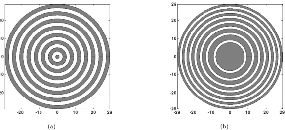
L’objectif de cette étude est donc le développement d’un transducteur ultrasonore à couplage air possédant une large bande passante en fréquence, un rendement élevé et pouvant être facilement focalisé, pour permettre son emploi dans un contexte très large de CND. Pour atteindre ce but, une sonde capacitive et multiélément a été mise au point, fabriquée et caractérisée. La sonde consiste en un arrangement concentrique d’éléments ca-pacitifs entourant un disque central. Dans toute la thèse, cette sonde est notée MEACUT pour Multi-Element Air-coupled Capacitive Ultrasonic Transducer. Avant de la fabriquer, un modèle basé sur l’intégrale de Kirchhoff (notée KIM pour Kirchhoff Integral Model ) est utilisé pour prédire le champ de pression acoustique (satisfaisant l’équation de Helmholtz) généré dans l’air par un disque, à partir du potentiel des vitesses en surface de ce disque. En se servant de la symétrie de révolution axiale des traducteurs (mono ou multi éléments, notés respectivement ACUT ou MEACUT), une intégrale simple de Kirchhoff (réduction de l’intégrale double de Kirchhoff traditionnelle) est employée et résolue en coordonnées cylindriques. Son expression courante contient une singularité numérique qui peut causer la discontinuité de la pression acoustique calculée dans le domaine. Une seconde expres-sion de l’intégrale de Kirchhoff, moins courante mais supprimant cette singularité gênante, est alors utilisée. Dans ce modèle, le phénomène d’absorption des ultrasons dans l’air est pris en compte en considérant un nombre d’onde complexe dans les paramètres de cal-culs. La partie imaginaire de ce nombre d’ondereprésente le coefficient d’absorption des ultrasons.
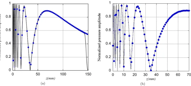
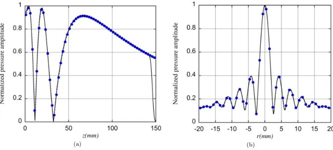
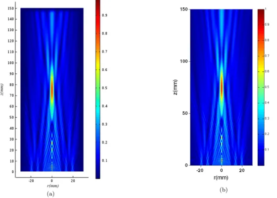
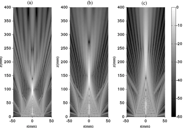
Traditionnellement employé pour calculer le champ de pression acoustique rayonné par un traducteur circulaire et mono-élément, le modèle intégral est utilisé par prédire le champ de pression rayonné par une source constituée d’un ensemble d’anneaux concen-triques avec un disque central. Ce champ de pression est calculé en utilisant le principe de superposition. Cette méthode, très simple, permet d’obtenir le champ rayonné par un des anneaux en soustrayant les champs de pression rayonnés par deux disques concen-triques. Ainsi, la pression acoustique produite par un traducteur multiélément analogue à celui imaginé peut être simulée. Des lois de retard bien spécifiques peuvent alors être appliquées à chacun des éléments, de manière à démontrer la possibilité d’une focalisation dynamique (variable suivant la loi de retard choisie). Elles sont définies dans le domaine des fréquences ; ce sont donc des déphasages proportionnels aux retards temporels néces-saires pour faire converger l’ensemble des champs produits par les éléments, vers un point commun dans l’air. Pour valider la pression acoustique prédite par la méthode KIM, un modèle de champ rayonné par un piston circulaire, basé sur la méthode des éléments finis (modèle axisymétrique lui même consolidé par ailleurs), est construit. Les distributions axiales et latérales de la pression acoustique, obtenues par les deux modèles (KIM et FEM)
sont en très bon accord. Le principe de superposition et son application pour prédire les champs acoustiques produits par un ou plusieurs anneaux sont également validés, démon-trant ainsi le potentiel de la méthode KIM pour simuler rapidement (1.5 à 15 fois plus rapide qu’un modèle FEM axisymétrique, selon le cas à traiter) le champ acoustique pro-duit dans l’air par un MEACUT, même pour des grandes distances de propagation. Par la suite, une validation complémentaire via des mesures expérimentales est effectuée.
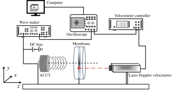
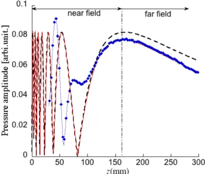
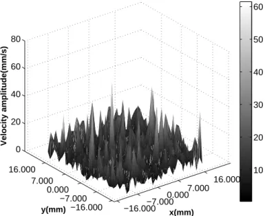
Les champs produits par les sondes multi éléments présentent, dans le cas général, des lobes latéraux secondaires (appelés « lobes de réseaux ») d’amplitude non négligeable et qui peuvent induire des artefacts peu souhaitables dans le cadre d’un contrôle par ultra-sons. En effet ces faisceaux parasites peuvent nuire à l’analyse en suggérant la présence de défauts multiples en réalité absents de la pièce contrôlée. De tels lobes de réseaux sont évités lorsque la distance inter éléments est inférieure à la moitié de la longueur d’ondes émise. A l’aide de la technique de fabrication disponible au laboratoire, une telle distance est difficile à obtenir pour des transducteurs à couplage par air (la longueur d’ondes des ul-trasons dans l’air est de l’ordre du millimètre aux fréquences des traducteurs utilisés). Une fois validé, l’outil numérique basé sur la méthode KIM est utilisé pour optimiser les car-actéristiques de la sonde multiéléments à concevoir. L’objectif est de produire une sonde présentant des propriétés optimales : un transducteur dont les dimensions et le nombre d’éléments sont compatibles avec les applications industrielles, permettant d’obtenir des faisceaux focalisés de grandes amplitudes, présentant des faibles dimensions de la tache focale et des lobes de réseaux dont l’amplitude, suffisamment faible, ne sera pas préjudi-ciable à l’utilisation de ces sondes. Ainsi, le nombre d’éléments du traducteur, leur taille et leur espacement sont des paramètres qui peuvent être optimisés grâce au modèle KIM. Une fois réalisé, le prototype MEACUT est alors testé via un banc de mesures ultra-sonores. Le dispositif expérimental consiste à mesurer le champ acoustique en utilisant un vélocimètre laser couplé à une membrane mince (d’épaisseur 5µm) en polymère placée entre le traducteur source et la sonde laser. Afin de pouvoir cartographier le champ de pression, le traducteur est monté sur un système de déplacement 3 axes. La réponse en fréquence du MEACUT a été mesurée et a révélé une très large bande passante pour ce prototype (≈ 150% à −20dB). Les distributions axiale et radiale du champ ont égale-ment été mesurées, et ont confirmé une faible amplitude des lobes latéraux indésirables en regard de l’amplitude du lobe central souhaité. Enfin, en choisissant convenablement la loi des retards pour les signaux d’excitation appliqués à chaque élément du MEACUT, il a été vérifié que la focalisation du MEACUT pouvait être ajustée, permettant alors de parler de traducteur à focalisation dynamique, et que la zone focale était clairement définie, de petite taille (bien plus faible que la largeur d’un faisceau produit par un ACUT ou mono-élément) et avec un niveau de pression supérieur ou égal à celui produit par un ACUT de diamètre équivalent. Les distributions des champs de pression mesurés ont été confrontées aux prédictions numériques de la méthode KIM. Les bons accords obtenus ont confirmé les validations faites par la méthode FEM, et aussi démontré que le prototype
Résumé en Français vii MEACUT avait été convenablement fabriqué et que ses performances étaient en bonne adéquation avec les attentes.
Par ailleurs, dans l’optique de simuler intégralement une expérimentation de CND mettant en jeu les traducteurs ultrasonores à couplage par air, un modèle hybride a été mis en place et employé. Il fait appel à deux méthodes intégrales pour calculer les champs acoustiques dans l’air (la méthode KIM mentionnée plus haut pour prédire le champ entre le traducteur émetteur et la plaque, puis une approche plus générale pour le champ entre la plaque et le traducteur récepteur), et à la méthode des éléments finis pour simuler la propagation dans la plaque. Les conditions de continuité de la vitesse normale, et de la pression dans l’air avec les contraintes en surface de plaque, sont appliquées pour raccorder les trois étapes de calculs. Les méthodes intégrales implémentées dans ce modèle allègent considérablement les ressources et les temps de calculs, par rapport à l’utilisation d’une méthode entièrement numérique, du type éléments finis ou différences finies, par exemple. Le modèle basé sur la méthode des éléments finis (FEM) a été construit pour simuler la propagation ultrasonore au travers d’une plaque placée dans le faisceau généré par le MEACUT. Le logiciel utilisé est Comsol Multiphysics. Il permet d’implémenter les équations d’équilibre dynamique et les conditions de frontières souhaitées dans un formalisme très général d’équations aux dérivées partielles (mode PDE). Il offre aussi une grande flexibilité vis-à-vis de la géométrie du domaine à simuler et de son maillage. Ainsi, le modèle développé décrit la propagation d’ondes acoustiques dans une plaque constituée d’un matériau anisotrope et viscoélastique placée dans le vide (compte-tenu de la grande différence d’impédance acoustique entre l’air et la plaque, cette approximation n’engendre qu’une faible erreur sur les champs calculés). Des modules d’élasticité complexes sont employés comme données d’entrée, et les équations sont résolues dans le domaine de Fourier (à une seule fréquence). Le formalisme adopté intègre la définition de régions absorbantes qui atténuent efficacement toute onde s’approchant des bords de la plaque, en augmentant progressivement la viscoélasticité du matériau et en abaissant dans les mêmes proportions sa masse volumique, ce qui permet de maintenir son impédance acoustique la plus constante possible. La plaque ainsi simulée peut être considérée comme infiniment étendue. Le champ de pression acoustique calculé par la méthode KIM, en coordonnées cylindriques, est alors exprimé en coordonnées cartésiennes tridimensionnelles et utilisé pour définir les conditions aux limites. Ainsi, la pression simulée et produite par un traducteur ultrasonore (ACUT ou MEACUT) peut être appliquée localement sur une surface de la plaque, dans le modèle FEM. La résolution du modèle PDE, sous Comsol, permet alors de prédire, entre autres, le champ de déplacement résultant en tout point de la plaque. Ainsi, ce champ peut aussi être prédit en surface arrière de la plaque, dans le champ de vue d’un traducteur récepteur qui serait disposé, dans l’air, et dans l’axe du traducteur émetteur.
A partir de la composante normale de la vitesse particulaire associée, ce champ est alors utilisé comme donnée d’entrée d’un second modèle intégral, connu sous le nom
d’intégrale de Rayleigh (RIM pour Rayleigh Integral Model ), permettant de calculer le champ de pression rayonné dans un fluide par une surface vibrante encastrée dans un baffle rigide. L’air situé derrière la plaque et la rigidité du matériau composant les plaques habituellement inspectées permettent, a priori, de satisfaire tout à fait les conditions requises par l’équation intégrale utilisée. Ce modèle RIM à trois dimensions (RIM 3D) provient d’une solution de la fonction de Green satisfaisant l’équation de Helmholtz-Kirchhoff. Les résultats obtenus avec RIM 3D ont tout d’abord fait l’objet d’une phase de validation. Pour cela, un modèle FEM axisymétrique a été construit, comportant une plaque dont une face est couplée à de l’air et l’autre face est totalement libre (couplée à du vide). Une excitation quasi arbitraire a été appliquée sur la face libre de la plaque et la résolution des équations PDE a permis de simuler la pression acoustique produite dans l’air. Par ailleurs, le champ simulé (par ce modèle FEM) des vitesses particulaires produites à la surface couplée à l’air a été relevé, exprimé en coordonnées cartésiennes tridimensionnelles et utilisé comme donnée d’entrée pour le modèle RIM 3D. Ce dernier a alors servi à calculer la pression produite dans l’air, en trois dimensions. Le très bon accord entre les deux jeux de pression ainsi prédits valide le modèle RIM 3D. Dans le cas ou le récepteur simulé est un MEACUT, le champ de pression acoustique peut être calculé dans l’air, et toujours à partir des vitesses normales relevées en surface d’une plaque, au niveau des surfaces des différents éléments (circulaire ou annulaires) supposés constituer ce MEACUT. Des lois de retard doivent alors être appliquées à ces champs localisés ; elles sont choisies en fonction de la distance entre la plaque et ce récepteur, de la vitesse de propagation dans l’air et de la focalisation désirée pour ce MEACUT. De la même manière que pour le MEACUT émetteur qui est simulé avec la méthode KIM, la focalisation peut être variable et ajustée selon les retards appliqués aux divers éléments du traducteur. On parle alors encore de focalisation dynamique, mais cette fois à la réception. Les champs déphasés sont ensuite sommés entre eux, ce qui permet d’établir la pression résultante détectée par le MEACUT récepteur.
Sur la base des travaux décrits précédemment, un modèle hybride KIM-FEM-RIM a été construit, en trois dimensions, en combinant les méthodes intégrales (semi)analytiques de Kirchhoff et de Rayleigh, et la méthode des éléments finis. Ce modèle complet permet de simuler intégralement une expérience utilisée en CND (connue sous le nom de C-scan) afin de repérer la présence de défauts dans une plaque. Dans la configuration dite « par transmission », cette expérience repose sur l’utilisation de deux traducteurs : un émetteur et un récepteur, qui sont placés de chaque côté de la plaque à contrôler. Elle consiste à mesurer l’amplitude du signal transmis à travers la plaque, pour différentes positions du couple émetteur-récepteur. La présence d’un défaut dans une plaque se traduit, lorsqu’il est de dimension suffisamment importante, par une chute de l’amplitude du signal trans-mis. Une telle expérience permet d’estimer ses dimensions apparentes dans le plan de la plaque, et ainsi d’en apprécier les conséquences sur l’intégrité de la pièce. Le modèle
Résumé en Français ix permettant aussi bien de simuler des traducteurs mono-éléments (ACUT) que multiélé-ments (MEACUT), deux configurations de contrôle sont simulées et confrontées à des expériences : une première dans laquelle sont utilisés un ACUT émetteur et un ACUT récepteur, et une seconde mettant en jeu un MEACUT émetteur et un ACUT récepteur. Les expériences correspondantes sont réalisées sur une plaque composite (verre polyester) comportant un endommagement causé par un impact, de dimensions apparentes 30mm par 18mm. La plaque est placée entre ces deux traducteurs et perpendiculairement à l’axe les joignant, puis déplacée pas-à-pas perpendiculairement à cet axe de manière à modifier la zone traversée par le faisceau ultrasonore. Dans chaque cas, les deux traduc-teurs ultrasonores sont disposés face à face et espacés d’une même distance. L’objectif consiste à vérifier si, pour cette application CND, l’emploi d’un traducteur MEACUT comme transmetteur (le récepteur demeurant un ACUT) améliore la résolution spatiale du C-scan, par rapport à l’utilisation classique de deux ACUTs, à quantifier cette amélio-ration ainsi que le rapport signal-sur-bruit associé. Cet objectif est atteint avec succès ; en effet, l’accroissement des performances du système, en termes de résolution spatiale et de rendement, est clairement démontré puisque le remplacement d’un seul ACUT par un MEACUT permet d’obtenir une image acoustique de la zone endommagée de cotés 40mm par 26mm au lieu de 80mm par 60mm. Ces résultats sont parfaitement confirmés par les prédictions du modèle hybride KIM-FEM-RIM. La réalisation d’une électronique multi-voies dédiée à l’utilisation de récepteurs capacitifs multiéléments est en cours, expliquant la raison pour laquelle seul l’ACUT émetteur a pu être remplacé par un MEACUT. Ces résultats confirment que l’objectif initialement fixé a été atteint, à savoir la modélisation, la simulation numérique, l’optimisation, la fabrication, la caractérisation et l’utilisation d’au moins un capteur ultrasonore à couplage par air, possédant une large bande pas-sante en fréquence, une focalisation efficace et éventuellement variable, et un rendement suffisant pour améliorer une application existante de CND. Le prototype réalisé est un tra-ducteur multiélément dont les performances ouvrent des perspectives prometteuses pour de futures applications de CND.
Contents
Acknowledgements i
Résumé en Français iii
Abbreviations xiv
Symbols xvii
Introduction 1
Thesis motivation . . . 1
Thesis context . . . 1
Air-coupled transducer and array . . . 2
Acoustic field simulation method . . . 5
Analytical methods . . . 6
Finite element method . . . 6
Thesis outline . . . 7
Chapter 1 Numerical modelling of acoustic field produced by air-coupled transducer 9 1.1 Introduction . . . 9
1.2 Kirchhoff integration method for axisymmetric transducer . . . 9
1.2.1 Kirchhoff integral modelling for a circular piston . . . 10
1.2.2 Ultrasound attenuation in air with Kirchhoff integral modelling . . 12
1.2.3 Annular superposition method for axisymmetric transducer . . . 13
1.3 Axisymmetric fluid-solid coupling finite element model . . . 14
1.3.1 COMSOL axisymmetric PDE formalism . . . 15
1.3.1.1 PDE formalism in air . . . 17
1.3.1.2 PDE formalism in solid . . . 18
1.3.2 Boundary conditions in fluid-solid coupling model . . . 19
1.3.2.1 Boundary conditions from fluid . . . 19
1.3.2.2 Boundary conditions from solid . . . 20
1.3.3 Absorbing region . . . 21
1.3.3.1 Viscoelastic Absorbing Region . . . 22 xi
1.3.3.2 Improved Viscoelastic Absorbing Region . . . 23
1.4 Validation of KIM with axisymmetric FE model . . . 23
1.4.1 KIM model for circular transducer validation with axisymmetric FE model . . . 25
1.4.2 KIM model for annular transducer validation with axisymmetric FE model . . . 27
1.4.3 Superposition KIM model for a MEACUT validation with axisym-metric FE model . . . 28
1.5 Summary . . . 30
Chapter 2 Air-coupled capacitive array: simulation, optimization, build-ing and characterization 33 2.1 Introduction . . . 33
2.2 Mono-element air-coupled capacitive transducer . . . 33
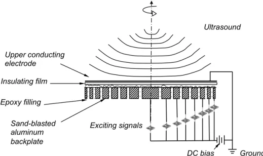
2.2.1 Configuration and ultrasound emission principle of ACUT . . . 34
2.2.2 Characterization of ACUT with laser vibrometry method . . . 36
2.3 Air-coupled capacitive annular array: optimization . . . 39
2.4 Air-coupled capacitive array: building . . . 45
2.5 Air-coupled capacitive annular array: characterization . . . 46
2.5.1 Acoustic field profile generated by MEACUT . . . 49
2.5.1.1 Acoustic field profile characterization of MEACUT elements 49 2.5.1.2 Focused annular phased array acoustic field characterization 52 2.6 Summary . . . 55
Chapter 3 Rayleigh integration method and 3D hybrid model 57 3.1 Introduction . . . 57
3.2 Rayleigh integration method . . . 59
3.2.1 Rayleigh Integral method for 3D modelling . . . 59
3.2.2 Rayleigh integration method: validation . . . 62
3.3 3D KIM-FEM-RIM hybrid model . . . 64
3.3.1 Axisymmetric KIM model for transmitter . . . 64
3.3.2 3D solid FE model . . . 65
3.3.3 3D RIM model for receiver . . . 69
3.4 Summary . . . 70
Chapter 4 Application of annular array for plate inspection 73 4.1 Introduction . . . 73
4.2 Experiments with annular ACUT/MEACUT . . . 74
4.2.1 Use of two ACUTs . . . 75
4.2.2 Use of transmitting MEACUT and receiving ACUT . . . 77
Contents xiii
4.3.1 Axisymmetric KIM model for incident acoustic field . . . 80
4.3.2 3D FE model for composite plate inspection . . . 80
4.3.3 3D RIM model for receiver and comparison with experimental results 81 4.4 Summary . . . 84
Conclusions and Perspectives 87 Conclusions . . . 87
Perspectives . . . 90
Appendix A Annular Integration method for calculating the acoustic field produced by axisymmetric transducers 93 Appendix B 2D Rayleigh integration method and 2D hybrid model 97 B.1 Rayleigh Integral reduction from 3D to 2D model . . . 97
B.2 2D hybrid model for air-coupled plate inspection . . . 99
B.2.1 2D air-solid coupling FE model . . . 100
B.2.2 2D RIM-FEM-RIM hybrid model building . . . 103
B.2.2.1 2D RIM model for transmitter . . . 103
B.2.2.2 2D solid FE model . . . 105
B.2.2.3 2D RIM for receiver . . . 106
B.2.3 2D RIM-FEM-RIM hybrid model validation . . . 106 Appendix C Hankel functions 109
Abbreviations
NDT&E Non-Destructive Testing & Evaluation UT Ultrasonic Testing
FEM Finite Element Method AR Absorbing Region
PAD Propagation Air Domain DoF Degree-of-Freedom
KIM Kirchhoff Integration Method RIM Rayleigh Integration Method PZT Piezoelectric Transducers SNR Signal-Noise Ratio
LDV Laser Doppler Velocimeter
ACUT Air-coupled Capacitive Ultrasonic Transducer cMUT capacitive Micromachined Ultrasonic Transducer
MEACUT Multi-Element Air-coupled Capacitive Ultrasonic Transducer
Symbols
a circular radius mm d circular diameter mm ρ material density g · cm−3 Cij material stiffness tensor GP a
Z acoustic characteristic impedance of material Rayl Kf bulk module of fluid GP a
c0 sound velocity in air mm · µs−1
α sound absorption coefficient in air dB · m−1· Hz−2
n unit vector normal to the boundary
u particle displacement in medium mm ν particle velocity mm · µs−1 p sound pressure in fluid P a, dB φ acoustic wave phase in fluid rad σ stress in solid GP a j complex number unit √−1 f frequency M Hz ω angular frequency rad · µs−1 k wave number rad · mm−1 G Green function
< real part operator for complex quantity = imaginary part operator for complex quantity F Fourier transform operator
Introduction
Thesis motivation
The motivation of this Ph.D work is the increasing demand of high-performance air-coupled ultrasonic transducers and their use for efficient NDT applications. Meanwhile, the development of an efficient numerical tool is also highly demanded in order to simulate the air-coupled acoustic wave generation, its propagation in the tested solid media and the output signal at the air-coupled receiver. Therefore, this thesis focuses on the promising capacitive air-coupled ultrasonic transducer to build a new type of multi-element trans-ducer, to explore its use for NDT applications, and to develop an analytical-numerical hybrid tool to simulate the whole ultrasonic inspection process.
Thesis context: State-of-the-Art
Numerous non-destructive testing and evaluation (NDT&E) methods [1, 2] have emerged in recent years, involving various domains of Physics, such as X-rays [3], in-frared rays [4], heat-transfer [5], magnetic field [6] or ultrasound. The advantage of these methods is that they enable the monitoring of the integrity of structures during their life, without having to destroy them. Through all the NDT methods currently used, ultra-sonic NDT has its specific advantages, such as non-radioactive, non-pollution and easy implementation. The application fields of ultrasonic NDT&E are wide and varied. For instance, the aeronautic industry needs to ensure the structural integrity of components used in the manufacturing and usage period of aircrafts [7]. The demand to detect defects in sensible zones so as to avoid accident caused by mechanical failures greatly boosts the development of NDE methods and technologies. Detecting damages or corrosion zones, which may occur in toxic chemicals storage sites, is also important. The preservation in ideal conditions of oil in cylindrical tanks, as well as of nuclear fuels or wastes in concrete containers [8, 9] or in granite caves, requires frequent inspection of the structures contain-ing these chemicals. The transport of materials, which may be dangerous, is also a topic for which the study of the integrity of pipes is required.
Generally, ultrasonic testing is based on the transmission, reflection and absorption of ultrasonic waves (bulk or guided waves) propagating in the tested object. The acoustic wave radiated by the emitter can be reflected or scattered at the defects or at boundaries
with discontinuous properties, then transmitted to the receiving transducers (single or multi-element) [10]. In the light of the acoustic wave used for the inspection process, the ultrasonic NDT could be sorted to testing based on bulk wave [11], shear wave [12], surface wave [13], guided wave [14]. For each wave type, there are specific advantages and drawbacks, and specific flaws that may be detected or not. Each detected ultrasonic signal is a signature, which depends on the interaction between the incident acoustic wave and the defect.
According to the exciting method of the ultrasound in specimen, the NDT method could be sorted to: contact transducer inspection method [15], water coupled transducer inspection [16, 17], laser generated ultrasonic inspection [18–20], Electromagnetic Acoustic Transducer (EMAT) inspection [21, 22], air-coupled transducer inspection [23, 24] etc.
The overall performance of an ultrasonic inspection and imaging system is mainly determined by the transducer characteristics. The transferring of acoustical energy from the transducer to the surrounding medium is essential for ultrasonic inspection. At each material boundary the amount of energy transfer is dictated by the acoustic impedances of the two materials [25] at either side of this boundary.
A common method used for ultrasonic inspection [26] is to contact a piezoelectric transducer with a couplant material and place it on the test specimen. The couplant layer needs only have a thickness of one tenth of a wavelength to affect the acoustic properties of the load as seen by the transducer. It is therefore important to choose the couplant on the basis of acoustic impedance as well as taking into account such variables as the viscosity, the acoustic impedances, the ease of removal of the couplant from the specimen surface. The contact transducer has been used in many industry applications [27]. Using the contact method has drawbacks such as the need to maintain a good degree of coupling, the roughness of the sample surface restrictions to the use of couplant, the consideration of contamination of the sample surface by the couplant, etc.
Another common method of coupling is to use water, either by use of an immersion tank [28] or by ensuring there is a constant flow of water around the transducer [17]. This testing method allows for automated scanning without wearing on the transducer. The acoustic impedance between the transducer and water or between the water and the tested object could ensure the appropriate energy transferring to the tested material. There are however many materials and industrial manufacture processes where the presence of water will cause damage or inconvenience. In addition the presence of water decreases the possibility of detecting surface flaws in polymer-matrices [29] and internal flaws in porous materials [30]. Materials such as foam, wood, paper products, reinforced plastics, propellants, pieces of art and many materials intended for the aerospace industry are not compatible with water. Thus the restriction of water coupling ultrasonic inspection leads to the research of the possibility and application of air-coupled ultrasonic inspection.
Introduction 3
Air-coupled transducer and array
Air-coupled ultrasonic inspection can be considered as a non-contact or minimally-invasive method, because the coupling medium (air or another gas) is part of the natu-ral environment and therefore non additional physical contact is required. Air-coupled ultrasound allows for rapid scanning without damage or contamination to the specimen materials. This non-contact technique could be applied to perform fast on-line inspection. The difficulty with air-coupled ultrasonic inspection lies in the huge acoustic impedance mismatch between the transducer, the air and the tested material, causing very little energy incident into the tested material and thus small signal to noise ratio at the re-ceiver. At the interface between water and steel, approximately 35% of the signal will be transmitted, however between air and steel this figure drops to approximately 0.5% [31]. For a common ultrasonic inspection system, there are four coupling interfaces: that between the transmitting transducer and the air, that between the air and the tested material, that between the tested material and the air, and the interface between the air and the receiving transducer. Thus the design of air-coupled transducers for the detection of signals having small amplitude is essential.
Mostly, there are two types of air-coupled ultrasonic transducers: piezoelectric trans-ducer and capacitive (electrostatic) transtrans-ducer. The air-coupled transtrans-ducer follows the similar fabrication method with the contact transducer, which mostly adopts piezoelectric ceramics or composite polymer as the resonance material. The piezoelectric air-coupled ultrasonic transducer (ACUT) system has been developed for decades. Traditional piezo-electric transducers [26] produce ultrasounds based on the piezopiezo-electricity principle, which is the ability of piezoelectric materials to generate mechanical stress in response to an ap-plied electric potential, so to convert electrical energy to mechanical energy. This kind of transducer is not suitable to directly emit ultrasound in air due to the large acoustic impedance mismatch between the transducer and the medium, which leads to a small refraction coefficient and a huge reflection coefficient, and consequently bad efficiency for emission of ultrasound in air. In air, for example, the generation of ultrasound is challeng-ing because the acoustic impedance of air (420 kg/(m2s), i.e. 4.2 × 10⁻⁴M Rayl) is orders of magnitude smaller than the impedance of piezoelectric materials commonly used to excite ultrasonic vibrations (approximately 30 × 106kg/(m2s), i.e. 30M Rayl). The large impedance mismatch implies that piezoelectric air transducers are inherently low trans-mitted efficiency. So the application of piezoelectric transducer in air-coupled ultrasonic detection domain usually use a matching layer [25] between the piezoelectric and the air which has a proper thickness and characteristic impedance to increase its efficiency for emission into air.
Recent development of air-coupling piezoelectric transducer (PZT) tend to improve existing piezoelectric ceramic, piezoelectric polymer transducer configurations. For ex-ample, the performance of thickness driving piezoelectric ceramic transducers may be enhanced significantly by incorporation of multiple matching layers [32] or the addition
of a radiating membrane to facilitate energy transfer into air. Piezoelectric polymer [33] and piezoelectric ceramic-epoxy composite materials [34] also offer attractive options for airborne ultrasound by means of improved mechanical matching and in the case of the piezoelectric polymers, the ability to be configured as a flexible membrane. A series of 1–3 connectivity piezo-composites [34] transducers has been proposed and revealed good promise applications. The commercial air-coupling PZT and array [35] has been put forward as a promising NDT solution.
However, the improved matching layer solution in air-coupled PZT is inherently prob-lematic for its frequency response performance. The principle of piezoelectric excitation decides the resonance properties, leading to transducers with very narrow frequency band-width. This drawback of PZT based air-coupled transducer reduces their field of NDT applications, for example, in the guided wave inspections, wide band acoustic field is re-quired to excite multi Lamb modes. Therefore, the exploration of wide frequency band air-coupled ultrasonic transducer has been carried out for NDT application purposes.
In recent years, some broadband ultrasonic transducers have been developed using PVDF (Polyvinylidene fluoride) transducers as another air-coupled transducer solution. There has been a great deal of development work on ultrasonic devices that take advantage of the inherent properties of piezoelectric polymers [36], that is their relatively good acoustic impedance match to water and tissue, their flexible form and availability in large sheets, their broadband acoustic performance, and the uniform surface displacement across the radiating aperture. The main restrictions to the application of PVDF as a transmitter in air [37] are the relatively low coupling factor and dielectric constant [38], resulting in poor performances.
Air-coupled capacitive transducer [39] can be an alternative solution with advantages and well promising applications for NDT. Air-coupled Capacitive Ultrasonic Transduc-ers (ACUT) have been developed over the last two decades [40], and successfully used for the contact-less inspection of composite structures. At the surface of the capacitive transducer, a metallised polymer membrane is used to reduce the acoustic impedance mismatching problem. There has been significant research interest in the development of these devices, for instance at the universities of Stanford [41], Warwick [42], Rome [43], Madrid [44], Tours [24, 45–47] and Bordeaux [48, 49]. Capacitive Micro-machined Ultra-sonic Transducers (cMUTs) [50] have demonstrated significant promise for application in air-coupled NDE, but may suffer from their fragile nature.
The main advantages of capacitive transducers include a very broad frequency band-width and a sufficiently high sensitivity for general non-contact NDT [51]. Several man-ufacturing techniques have been reported, including series of coarse polishing machining V-shaped grooves [52] or circular holes through laser ablation [53], photo lithography [54], or sand blasting [55] so that obtained roughness or cavities at the surface of the metal-lic back-plate determine the frequency properties of the capacitive ultrasonic transducer. Also, these elements require a few-micron thick membrane deposited on the back-plate,
Introduction 5 with metallised external surface. This membrane must be stretched for the transducer to operate, thus producing locally plane wave front and introducing difficulties in allowing the focusing of the ultrasonic beam. Consequently, because they cannot be easily focused, these capacitive elements have low spatial resolution, as a serious drawback for some NDT applications. In order to circumvent this problem, a method has been proposed using a micro-machined Fresnel zone-plate placed in the acoustic field [56]. A flexible back-plate [57] as been developed as an alternative solution, allowing the realization of concave ca-pacitive air-coupled transducers. With micromachining fabrication technology [58] on the silicon back-plate a micro-electromechanical system for cMUT has been developed re-cently. However, these solutions offer fixed focusing features [59] and as many transducers as intended focusing conditions will be required for satisfying several NDT inspections. As a further development, by assembling several capacitive elements and applying properly phased delays to each of these elements, a wide-frequency band, dynamic-focusing array will be developed in this thesis work.
The limitation of single element transducer in beam controlling and spatial sensitiv-ity promotes the emerge of phased array transducer [60]. A phased array transducer [61] consists of multiple elements, each of which is analogous to a single element transducer, capable of emitting and receiving ultrasonic waves. Ultrasonic arrays offer two key advan-tages over standard monolithic transducers. Firstly, a particular array is able to undertake a range of different inspections and thus is more flexible than a single element transducer. In fact, an ideal array can generate ultrasonic fields of almost infinite variety. However, they are most commonly used to produce fields similar to those from traditional single element transducers, i.e. plane, focused and steered beams. Secondly, most types of array can be used to produce images at each test location. This allows rapid visualisation of the internal of a structure. By controlling the pulsed time of the elements, the beam generated by the array can be electronically focused and steered. These reasons and the flexibility lead the phased arrays becoming more commonly used in ultrasonic non-destructive test-ing. Ultrasonic phased array transducers have been around for more than two decades, mostly in applications of many medical specialities [62]. Various ultrasonic phased arrays are also introduced in industrial applications [63]. A new ultrasonic technique combining the air-coupled capacitive technique and the phased array concept is introduced in this thesis. Under this research and application context, a new Multi-Element Air-coupled Capacitive Transducer (MEACUT) is proposed in this work.
Acoustic field simulation method
The availability of numerical models that can accurately simulate ultrasonic NDT is a continuous and demanding research topic. Many methods are used for the acoustic field calculation, and they can be classified into analytical methods, numerical methods (finite element method, finite difference method, boundary element method, etc.) and hybrid methods.The Finite Element Method (FEM) has been widely used to solve various kinds
of acoustic problems for years [64], due to its ability to handle complicated geometries (and boundaries), inclusion of dissimilar material properties, availability for various physical problems, etc..
As their name suggests analytical techniques resolve problems by implementation of available closed form formulas while FEM employs a discretization of the medium for solving the differential equations governing the problems. The analytical methods to calculate acoustic fields include several methods such as angular spectrum method (ASM) [65, 66], Pencil method [67, 68], Multi-Gaussian beam method (MGB) [69] and Rayleigh Integral Method (RIM) [70, 71], etc. For the Rayleigh integration method, closed form formulas considering the shape of the transducer and transmitting condition are mathematically deduced from the general Huygens principle [72, 73]. Despite of this, mostly a regular shaped transducer or acoustic source is demanded to get an efficient mathematical integration formula. In this work, the analytical Rayleigh integral method will be developed and used to solve the ultrasonic NDT problems.
Analytical methods
The analytical integration method is basically Rayleigh integration method (RIM), the conception of which comes from Huygens principle in optics [74]. It resumes that the acoustic field in an arbitrary field point in medium is the integration of all the elements on the source which radiates spherical acoustic wave, which could be represented by a Green source function. This method can be represented that the disturbance of one point in space is the overall integration by spherical wave radiation source elements. For cases with regular shaped source or uniformed surface velocity, the integral formula could be mostly simplifies from double surface integration to single integration. These situations of acoustic field calculation greatly simplify the integration expression and increase the capability of short calculation time. The application of Kirchhoff integral method (KIM) to a disk radiator requires ideally that the acoustic medium vibrates uniformly at the front surface.
Finite element method
The finite element method, which is based on a discretization of the medium area to solve the differential controlling equation and certain boundary conditions, originated from the need to solve complex elasticity and structural analysis problems in civil [75] and aeronautical engineering [76]. The method has been developed for nearly 40 years [77], and has been used in wide range of physical and engineering area, for instance thermology, acoustics, electricity and mechanics. The capability of the FE method to meshing the unsolved area with multi-physical field has boosted its application in field coupling areas [10, 78]. As the development and the advance of computation method and computer capacity grow up, several physical problems which are time-consuming or impossible to
Introduction 7 solve had been treated. The precision has been confirmed in various physical domains, however, the low velocity of sound in air and large number of Degrees of Freedom (DoF) have limited the use of FEM for air-coupled ultrasonic NDT simulations [79–81].
The main advantage of the finite elements approach is its capability to simulate the propagation in complex structures, with or without defects [14] and for various shapes of transducers [82] like, for instance, focused transducers or phased arrays. Almost all the acoustic simulation problems encounter the unbounded problem [83] which requires infinite space to avoid reflection from boundaries. Most numerical treatments to reach this purpose include infinite elements [84], absorbing layers [79, 85, 86], local absorbing boundary conditions [87], or boundary integration method [88].
The applications of FE methods in acoustics have boosted various commercial pack-ages such as COMSOL, ANSYS, ABAQUS, MARC, etc. It is worth mentioning that most of the commercial packages have interactive user-friendly pre and post-processing tools which greatly increase their flexibility and ease of use. The choice of commercially available FE packages is also motivated by the fact that they enable new solutions to be quickly transferred to industry where these products are already or could easily be available, and where a specific unsupported research code would be difficult to maintain. The FE package selected and used in this work is COMSOL Multiphysics [78] (for-merly known as FEMLAB). The pre and post-processing packages used in this work for analytical calculation of acoustic field analysis is Matlab [89]. The software supports dis-tributed computing with cluster computers, which is indispensable for 3D simulation for plate inspection in this work. For 3D simulations with large number of DoF which are out of the computing capacity with personal computer, the computing cluster Avakas [90] available at Université Bordeaux 1 has been adopted.
Thesis outline
This thesis focuses on the simulation of the acoustic field with numerical methods and their validations, the optimization, designing, fabrication and characterization of MEA-CUT, the application of this ultrasonic transducer to the NDT plate inspection and the development corresponding hybrid model to simulate the inspection process. In Chap-ter 1, the theoretical tools have been introduced and deduced for calculating the acoustic field pressure generated by axisymmetric transducers (i.e. circular, annular transducers). The numerical tools include the analytical axisymmetrical Kirchhoff integration method (KIM) and the fluid-solid coupling axisymmetric FE model. The analytical KIM model has been compared and validated with numerical FE model. In Chapter 2, the annular MEACUT has been optimized with the KIM model and designed with proper parameters in order to get the desired acoustic profile for further applications. Annular array made up of 8 elements with the same surface area has been fabricated with manufacturing technique of ACUT and characterized using laser Doppler Velocimetry to test its frequency response
and its radiated acoustic field performance. The predictions by KIM model are compared with the characterization results, revealing its capability in the simulation of the acoustic field produced by MEACUT. In Chapter 3, the analytical Rayleigh integration method (RIM) is introduced, developed in 3D cases. This 3D RIM model has been validated with a non-piston excitation axisymmetric FE model. Together, a 3D KIM-FEM-RIM hybrid model is built to simulate the whole process from an axisymmetric transmitter to the receiver in the air-coupled plate through-transmission inspection. In Chapter 4, the built MEACUT is experimentally used for inspection of a composite plate with an impact damage. The through-transmission scanning of the plate is first proceeded with a pair of single element ACUT, and then one transmitting MEACUT with one single element ACUT. The experimental results agree well with the predictions of the 3D KIM-FEM-RIM hybrid model. In the end, a conclusion of this thesis is presented including main contributions and problems, as well as the prospectives and suggestions for the future work.
Chapter 1
Numerical modelling of acoustic field
produced by air-coupled transducer
1.1
Introduction
In the air-coupled ultrasonic inspection system, the air-coupled transducer aperture is axisymmetric, either circular or annular. So for decreasing the calculating amount of the acoustic field pressure produced by the air-coupled transducer, an axisymmetric ap-proach will be adopted both for Kirchhoff integration analytical model and FE model. An efficient Kirchhoff integral method (KIM) based on Rayleigh integration method (RIM) is developed for circular and annular transducers. This Kirchhoff model uses a single inte-gral expression to calculate the radiated field by capacitive or piezoelectric transducer in a fluid (air) that greatly simplifies the field calculation process and decreases the calculating time of the NDT system simulation in comparison to the FE model.
As a widely used numerical tool, an axisymmetric FE model is developed for the validation of the analytical method. The building of this axisymmetric FE model mainly includes the following three parts: setting of partial differential equations (PDE) formalism and boundary conditions according to the COMSOL formalism [78] which will be described further down; construction of the geometry and meshing to realise the discretization of the domains; properly setting of the absorbing region.
1.2
Kirchhoff integration method for axisymmetric
trans-ducer
The starting point for modelling of the acoustic fields radiated by transducer or scattering objects is the development of integral expressions. On geometrical aspect, the transducers used in this work are either circular or annular. To simulate the acoustic field pressure produced by these transducers, the axisymmetric integral model either for circular or for annular transmitter will be built analytically in the following sections. The
Kirchhoff integration method developed from the Huygens principle for axisymmetric source, is introduced and derived from the Helmholtz equation. The objective of this section is to develop an efficient integration formula for axisymmetric transducers.
1.2.1
Kirchhoff integral modelling for a circular piston
In theory, either Rayleigh integral or Kirchhoff integral is employed to obtain the acoustic field distribution of a transducer. However, the Kirchhoff integral is a simpli-fication approximation of the double Rayleigh integrals. For the radiation elastic body with regular shape, in our cases, circular or annular piston transducer, Kirchhoff integral supplies a simple expression for steady wave field distribution with reasonable calculating time. Further this expression of Kirchhoff integration is easy to implement for numerical calculations. For those reasons, the Kirchhoff integral is then deduced and simplified from the impulse response of a circular radiation object.
The integration method ordinarily assume that the velocity profile across the surface of the transducer is spatially uniform, although other improved models permit some ra-dial variation in the velocity profile. The following acoustic radiation mechanism study and experimental measurement of the acoustic field produced by a capacitive air-coupled transducer verify this precondition of the integration method. The impulse response is primarily used for pulsed mode calculations in the near-field region; however, this model is also suitable for time harmonic pressure calculations in the far field.
Two equivalent single integral expressions are described by Archer-Hall [91] and Hutchins [92] specifically for time-harmonic near-field calculations of the pressure gen-erated by a circular piston with infinite baffle around (i.e. clamped condition all around the circular piston). The expression in [91] applies a cylindrical coordinate system with a movable origin to the solution of the Kirchhoff integral. These geometric manipulations convert a double integral into a simplified single integral.
The impulse response for a circular piston in time domain, defined as h(r, z; t), is a function of temporal and spatial parameters in cylindrical coordinate system. It is applicable to time-harmonic acoustic pressure calculations with the Fourier transform. H(r, z; ω) is the temporal Fourier transform of the impulse response h(r, z; t), which is derived as: H(r, z; ω) = F {h(r, z; t)}. Starting from a harmonic and uniform vibration of the transducer surface, the temporal velocity of the surface is V (t) = ν0ejωt, where ν0
is the uniformed normal velocity at the surface of the piston, t is time. The steady-state pressure at a certain point in the propagation medium p(r, z; ω) can be derived by the equation according to:
p (r, z; ω) = −jωρνH(r, z; ω)e (1.1) where ω is the excitation angular frequency in radians per second, ρ is the density of the medium, j is the complex number unit defined by j =√−1,eν is the Fourier transform of
1.2.1. Kirchhoff integral modelling for a circular piston 11 V (t). Thus H(r, z; ω) is directly proportional to the pressure distribution. The integra-tion coordinate for the simplificaintegra-tion of H(r, z; ω) is illustrated in Figure 1.1. A circular acoustic radiation object with radius a is located at cylindrical coordination (r, z), where the circle centre is the coordinate origin. The integration formula reflecting the spatial impulse response from the surface vibrating element follows an arc-shaped integral geom-etry perpendicular to the line running from the disk (source) centre, o, and the projection of an observation point M(r,z) onto the source surface, i.e. point N. Central angle cor-responding to the integral arc ψ is regarded as the integration variable for taking into account the overall contribution of the surface element.
N
z
M(r,z)
S
a
z
r
!o
Figure 1.1. Axisymmetric coordinate system for Kirchhoff integration.
An expression on the transfer function of the circular source [91, 93] is given: H(r, z; ω) = ac jωπI + c jωe −jωz/c 1, r < a 1 2, r = a 0, r > a (1.2) where I is the integral expression defined by:
I(r, z; ω) = Z π 0 rcosψ − a r2+ a2− 2arcosψ × e −jω√r2+a2−2arcosψ+z2/c dψ (1.3) in which a is the radius of the circular transducer, c is the a complex number related to the sound speed in air, with c = ω/k, k is the complex wave number with k = k0+ αj,
where k0 is the real wave number in air defined by k0 = ω/c0, where c0 is the ultrasound
velocity in air, and α is the absorption coefficient of ultrasound in air which will be discussed later on. In Equation 1.2, the term (c/jω)e−jωz/c is multiplied by 1, 1/2, 0 according to the location along the radial coordination r relative to the circular edge. This expression takes the contribution of the circular source integration element to obtain the spatial impulse response distribution in cylindrical coordination. However the integral in Equation 1.3 contains a numerical singularity which is encountered when r ≈ a and ψ ≈ 0. This singularity is responsible for increasing the numerical errors in all spatial location
where r ≈ a. This may result in a discontinuity in the field distribution at the radius boundary r ≈ a. Although an improved integrand numerical method can be used such as Gauss quadrature, increasing numerical errors are generated in this expression around the location r ≈ a. The numerical singularity problem can be eliminated by subtracting a singularity from the exponential term in the numerator of integration Equation 1.3 by e−jωz/c0. The resulting integration divides an infinitesimal number by another infinitesimal
number where r ≈ a and ψ ≈ 0, and reduces the error at the location around r ≈ a. This improvement gives rise to an efficient formulation [94] of the acoustic field generated by a circular piston transducer as following:
H(r, z; ω) = ac jωπ Z π 0 rcosψ − a r2+ a2− 2arcosψ × (e −jω√r2+a2−2arcosψ+z2/c − e−jωz/c)dψ (1.4)
The integration expression for the spatial impulse response in Equation 1.4 can be also derived equivalently from Green’s function approach that generates a double Bessel functions in cylindrical coordination and then simplifies an integration by using Hankel transform tables [95]. The efficient integration of Equation 1.4 is derived from the Kirch-hoff integral method from the Helmholtz acoustic wave equation [73]. Applying numerical integration operation in the integral, the spatial impulse response and further acoustic pressure at any spatial position can be obtained straightforwardly. Therefore, this ana-lytical Kirchhoff integral method will be used in the following calculation of the acoustic field produced by circular air-coupled capacitive transducers.
1.2.2
Ultrasound attenuation in air with Kirchhoff integral
mod-elling
As what has been written in the general Introduction of this work, one of the chal-lenges for air-coupled ultrasonic inspection is the attenuation of ultrasonic wave along its propagation in air. In the Kirchhoff integration modelling, the acoustic propagation medium properties are included in the model by the medium density ρ and sound velocity c0. The acoustic attenuation effect of wave propagation in medium can be regarded as
a complex sound velocity, the imaginary part of which is related to the total effects of acoustic attenuation in medium [72, 96], such as gas viscosity, relaxation absorption and heat conduction, etc. [97].
For acoustic plane wave propagating in medium with single frequency, i.e. time-harmonic wave, its acoustic pressure is
p(x, t) = p0e−α|x|ej(k0·x−ωt) (1.5)
where x is the vector from the source to the spatial point, α is the acoustic absorption coefficient in air, k0 is the wave number, defined by k0 = 2π/λ · n, where n is the wave
1.2.3. Annular superposition method for axisymmetric transducer 13 propagation direction vector, λ is the wave length. In Equation 1.5, by applying a complex wave number in the form of k = k0+ αj, where k0 is the real wave number in air defined
by k0 = ω/c0, where c0 is the ultrasound velocity in air. The complex acoustic velocity
c = ω/k can be substituted into the Kirchhoff integral in Equation 1.4.
For the absorption coefficient in air under the frequency range used in NDT, an empirical power law expression energy losses of ultrasound in air has been found to be [98, 99]:
αdB = 1.64f2× 10−10(dB/m) (1.6)
where f is the frequency. From the following comparison between experimental measure-ment and the model taking into or not the absorption effect of ultrasound in air, this ultrasound attenuation in air under the ultrasonic range is not negligible. Thus, in the analytical model and FE model which will be described further down, this air absorption effect will be included in these models.
1.2.3
Annular superposition method for axisymmetric transducer
z r a b b a o Ca Cb Aab
Figure 1.2. Schematic for calculating the acoustic field pressure produced by annular piston through subtracting the contribution between two circular piston.
As the pressure calculation is based on the assumption that every spot at the surface of the piston radiates spherical wave to the medium, the field generated by an annular source can be deduced through the subtraction between the acoustic fields generated by two discs whose diameters are equal to the outer and inner ones. The schematic of this process to obtain the acoustic field produced by an annular piston is shown in Figure 1.2. The acoustic field produced by annular Aabis the subtraction between the fields produced
by two circular Ca and Cb, i.e.