Catalyst Immobilization Techniques for
Continuous Flow Synthesis
by
7~~
FEB
0
8 21
Kevin David Nagy
LIBRARIES
B.S. Chemical and Biomolecular Engineering, Georgia Institute of Technology, 2006
M.S. Chemical Engineering Practice, Massachusetts Institute of Technology, 2007
ARCHIVES
Submitted to the Department of Chemical Engineering
in partial fulfillment of the requirements for the degree of
Doctor of Philosophy in Chemical Engineering
at the
MASSACHUSETTS INSTITUTE OF TECHNOLOGY
February 2012
C 2011 Massachusetts Institute of Technology. All rights reserved
Author
Department of Chemical Engineering
November 18, 2011Certified by
Klavs F. Jensen
Warren K. Lewis Professor of Chemical Engineering
Professor of Materials Science and Engineering
Thesis Supervisor
Accepted by
William M. Deen
Carbon P. Dubbs Professor of Chemical Engineering
Chairman, Committee for Graduate Students
Catalyst Immobilization Techniques
for Continuous Flow Synthesis
Kevin D. Nagy
Submitted to the Department of Chemical Engineering on November 18, 2011 in partial fulfillment of the requirements for the degree of
Doctor of Philosophy in Chemical Engineering
Catalytic processes are ubiquitous in both research and industrial settings. As continuous flow processes continue to gain traction in research labs and fine and pharmaceutical chemical processes, new opportunities exist for implementing previously difficult catalytic transformations. The major goal of this thesis is to expand and evaluate techniques for immobilized catalyst systems relevant to continuous flow. Fundamental studies in characterizing mixing, dispersion, and residence time distributions in small scale continuous flow systems are also presented. Given the numerous benefits associated with studying chemical processes at small length scales, microfluidic devices are the tool of choice for most studies in this thesis. Thermomorphic solvents offer the potential for homogeneous catalytic processes with biphasic catalyst recovery and recycle. A major limitation of these processes is the number of
synthetically useful thermomorphic solvent combinations demonstrated in literature. A
screening program using the modified UNIFAC (Dortmund) activity coefficient model to evaluate phase splitting behavior has been developed to predict thermomorphic behavior. Calculation of 861 binary solvent combinations results in 43 potential thermomorphic and 44 biphasic solvent combinations. Extension of the program to ternary solvents resulted in a new class of ternary solvents that display thermomorphic behavior with tunable critical solution temperatures. Evaluation of thermomorphic processes as a general method is presented.
Traditional catalyst immobilization techniques rely on covalent grafting and are well suited to continuous flow processing due to the strong interactions of the catalyst to the support. Fluorous physisorption, which relies on interactions between a fluorous support and a fluorous-tagged catalyst, is characterized and presented as an immobilization technique for flow chemistry. The use of a fluorous-tagged Co(III)-salen catalyst to effect the ring opening of epoxyhexane with water is presented. Application of the platform to the ring closing metathesis of N,N-diallyltosylamide using a fluorous-tagged Hoveyda-Grubbs metathesis catalyst results in
significantly accelerated loss of activity over time compared to the salen catalyst.
Use of continuous flow selective adsorption reactors to enhance catalytic processes is presented. Continuous feeds of a homogeneous catalyst into a sorbent where the catalyst displays an affinity for the sorbent results in accumulation of the catalyst in the packed bed. The net effect is an enhancement in turnover frequency and turnover number relative to homogeneous flow. Application of this platform to a Lewis acid catalyzed Diels-Alder reaction results in an order of magnitude improvement in turnover frequency compared to batch and homogeneous flow.
Thesis Supervisor: Klavs F. Jensen
Title: Warren K. Lewis Professor of Chemical Engineering Professor of Materials Science and Engineering
Acknowledgments
Completion of a PhD program at MIT was perhaps the most challenging endeavor I have undertaken. I am very grateful for the support of my family, friends, and research group over the years. The Boston/Cambridge area is a wonderful place to live as a young adult, and I will cherish my time in the city.
I am very fortunate to have had Prof. Klavs F. Jensen, who has been a great inspiration
during my tenure, as my advisor. His tremendous ability to diagnose problems with fundamental engineering and scientific principles was enormously helpful throughout my PhD and has strongly influenced the way I approach problems.
Interactions with my thesis committee proved valuable in guiding my research. In particular, Prof. Steve Buchwald, whom I deeply admire, always made sure the projects I pursued were both relevant and important with his honest feedback. Prof. Greg Rutledge had a keen eye for the critical aspects of the project and provided useful feedback, especially on the thermomorphic modeling project, and Prof. Richard Schrock offered many useful comments on chemistry.
Greatly have I enjoyed interacting with colleagues in my research group. I will fondly recall the trips to the Muddy Charles, coffee breaks, and meals together, along with many fruitful discussions about research. I'd particularly like to thank my mentors along the way. Hemant Sahoo introduced me to many of the concepts important in microfluidics, taught me how to fabricate microreactors, and tried to instill in me how to be a successful graduate student. I am grateful for John Naber's willingness to teach me useful synthetic organic bench techniques early in my PhD. Nikolay Zaborenko's enthusiasm, practical approach to research, and Russian metabolism are legendary, and I always strived to emulate Ryan Hartman's focus and tenacious approach to problem solving. Listing similar accolades for everyone from the group over the
years would take several pages, so I would just like to thank Vicki, Jerry, Jason, Patrick, Sam, Victor, Baris, Xiaoying, Simon, Everett, Jinyoung, and Jon for their meaningful interactions.
I was fortunate to have the opportunity to collaborate with several people during my
research. Damian Young at the Broad Institute and the wonderfully talented Lars Johansen from
DTU (not Delft!) were instrumental in the success of the fluorous immobilization project.
Masaya Hamano was kind enough to teach me about Japanese culture while we worked together, Dima Tsvelikhovsky was as diligent a collaborator as anyone could hope to have, Bo Shen and Damien Webb were instrumental in the success of the last projects I worked on, and hopefully Everett O'Neal will be able to expand and continue my work.
My interest in research came from my co-op at Roche and during my research at Georgia
Tech. My mentors at Roche, Bert Miranda and Dr. Pingsheng Zhang, allowed me to work in several different areas of the site. The formative semesters I spent doing research in Prof. Christopher Jone's lab under the tutelage of Joe, Jason, and John fostered my interest in catalysis.
The friendships I made during my time at MIT were numerous - specifically I'd like to thank David and Becky, CJ and Stephanie, Jerry and Meredith, Nick, and Zach for always being there for me. Andy, Seth, and the rest of the PSC group were great at reminding me about life outside of building 66, and the continuing friendships of my college group - Derek, Greg, Sanders, Ken,
Ben, and Kelly - made vacations a lot of fun.
This thesis would not have been possible without the support, encouragement, and love of my dear wife, Sara. I am forever grateful for you.
I dedicate this thesis to my parents, Bert and Laura, and my sister, Sarah, who have loved and
Table of Contents
Chapter 1
1.1 1.2 1.3 1.3.1 1.3.2 1.3.3 1.4Chapter 2
2.1 2.2 2.3 2.4 2.5 2.6 2.7 2.8Chapter 3
3.1 3.2 3.3 3.4 3.5 3.6 3.7 3.8Background, motivation, and objectives...
19
Importance and fundamentals of catalytic processes... 19
Traditional catalyst immobilization techniques...21
Microreactors for studying catalytic processes...24
Homogeneous liquid phase processes ... 27
Multi-phase liquid-liquid and gas-liquid catalytic processes ... 28
Solid supported catalytic processes ... 31
Specific thesis objectives and outline... 33
A general platform for characterizing single-phase and
multi-phase residence time distributions...
37
M otivation... . 37
Review of theory of residence time distributions ... 38
Inline UV-Vis spectroscopy setup ... 42
Experimental protocol ... 46
Data analysis algorithms... 49
Single phase liquid results ... 51
Multi-phase liquid-liquid and gas-liquid results... 54
C onclusions... . 59
Mixing and dispersion in small scale flow systems ...
61
M otivation... . 6 1 Reactor model selection... 62
Dispersion effects in flow systems ... 65
Analysis of mixing...68
A simplified Damk6hler number ... 75
An analysis chart for flow systems...77
Experimental verification using a glycosylation reaction ... 78
3.9
Chapter 4
4.1 4.2 4.3 4.4 4.5 4.6 4.7 4.8 4.9Chapter 5
5.1 5.2 5.3 5.4 5.5 5.6 5.7 5.8 5.9 5.10Chapter 6
6.1 6.2 C onclusions... 83Expanding the pot of thermomorphic systems using activity
coefficient models ...
85
M otivation... . 85
Batch catalyst recycling using thermomorphic processes ... 87
Phase stability criteria of liquid-liquid systems... 89
Screening algorithm for binary thermomorphic solvents ... 92
Comparison of activity coefficient models...94
Binary screening results...100
Tunable ternary thermomorphic solvents ... 108
Evaluation of thermomorphic processes...114
C onclu sion s...115
Evaluation of fluorous physisorption as a catalyst
immobilization technique for flow systems...117
M otiv ation ... 117
Evaluation of non-covalent immobilization techniques ... 118
Packed-bed microreactor design, fabrication, and performance ... 120
Fluorous-tagged phosphine oxide retention on fluorous silica gel...126
Catalyst loading procedure ... 129
Fluorous silica gel characterization ... 131
Fluorous-tagged Co(III)-Salen catalysts...133
Catalyst recycling using multiple beds in series...138
Fluorous-tagged metathesis catalysts ... 140
C on clu sion s...14 9
Catalytic process enhancement using continuous flow selective
adsorption reactors ...
151
M otiv ation ... 15 1 Mathematical treatment of selective adsorption processes...153
6.3 6.4 6.5 6.6 6.7
Chapter 7
7.1 7.2Hoveyda-Grubbs ring closing m etathesis exam ple ... 159
Lewis acid catalyzed Diels-Alder exam ple ... 165
Series-parallel and equilibrium applications ... 169
Potential lim itations of adsorption reactors ... 171
Conclusions...172
C onclusions and O utlook...
175
Sum m ary of thesis contributions ... 175
Future Outlook...178
References ...
181
Appendices
A...
201
MATLAB programs for RTD analysis ... 201
Analytical y parameter derivations ... 207
MATLAB program for binary UNIQUAC calculations ... 213
MATLAB program for binary UNIFAC-Do calculations ... 215
Microfabrication protocols and masks... 221
List of Figures
Figure 1.1 - Selected examples of heterogeneous catalyst immobilization using covalent
attach m ent. ... 22
Figure 1.2 - Comparison of homogeneous and heterogeneous Pd-sources at 0.05 mol% loading for the Heck reaction of 4-iodo methoxybenzene with ethylacrylate... 23
Figure 1.3 - Complex integrated microfluidic devices. ... 24
Figure 1.4 - Halo-etched reactors enable high temperature-high pressure reactions. ... 25
Figure 1.5 - Auotomated experimentation represents some of the most promising applications for m icrofluidics ... 26
Figure 1.6 - Murahashi cross coupling achieved using continuous flow technology... 28
Figure 1.7 - Pd-catalyzed oxidations of secondary alcohols to ketons under continuous flow conditions at a total system pressure of 500 psi. ... 29
Figure 1.8 - Use of packed beds comprising stainless steel beads was found to accelerate biphasic Pd-catalyzed amination reactions ... 31
Figure 1.9 - Microfabricated devices for studying supported catalysts.. ... 32
Figure 2.1 - Pulse injections (left) and step change (right) experiments for performing residence time distribution experiments ... 39
Figure 2.2 - Schematic of inline UV-Vis platform for performing RTD experiments. ... 43
Figure 2.3 - Pulse injection RTD experimental setup... 44
Figure 2.4 - Step change RTD experimental setup.. ... 44
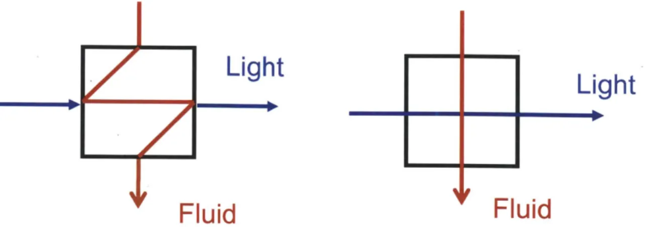
Figure 2.5 - Comparison of flow schemes through a "Z" cell and "cross" flow cell... 45
Figure 2.6 - Mounted cross flow cell with immobilized tube; fiber optic cables would connect to the SMA threads on the front face. ... 46
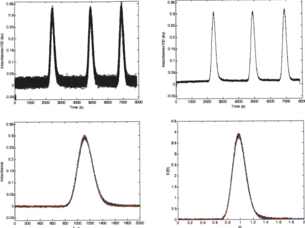
Figure 2.7 - Single phase RTD measurements... 52
Figure 2.8 - Use of RTD platform to measure packing efficiency of a microfluidic packed b ed reactor... 53
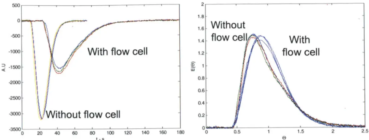
Figure 2.9 - Use of RTD platform to measure internal volume of an inline FTIR flow cell. ... 54
Figure 2.10 - Unfiltered water-hexane behavior through Z flow cell... 55
Figure 2.11 - Wetting characteristics of native oxide (top) and PTFE coated (bottom) microreactors for liquid-liquid multi-phase flows... 56
Figure 2.12 - Clean multiphase liquid-liquid RTDs obtained using a cross flow cell... 56
Figure 2.13 - Multiphase GL RTD of a union using the cross flow cell... 58
Figure 2.14 - Comparison of multiphase GL RTD of a microreactor and packed bed... 59
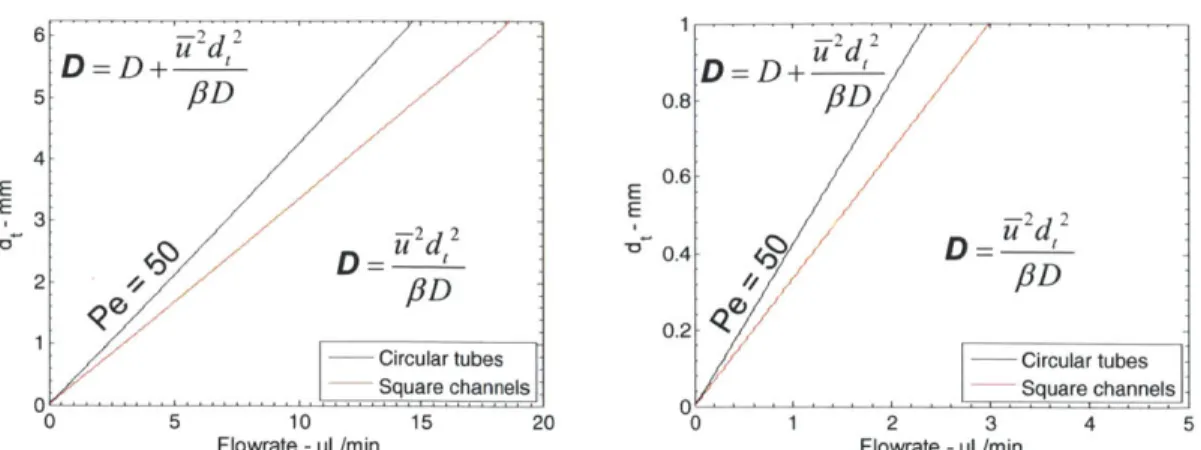
Figure 3.1 - Tielines for Ped=50 in both square channels and circular tubes. ... 65
Figure 3.2 - Magnitude of dispersion effects in circular tubes and square channels. ... 66
Figure 3.3 - Effect of diffusion coefficient on dispersion phase diagram... 67
Figure 3.4 - Concentration profiles of A for DaA=DaB=0.04 and DaA= DaB=4 ---... 70
Figure 3.5 - Concentration profiles of A for DaA=0.4, DaA=1.6 and the concentration profiles for B for both cases... 71
Figure 3.6 - Enhanced byproduct potential due to the presence of concentration gradients. .... 73
Figure 3.7 - Best fit of rate constants from COMSOL simulations. ... 74
Figure 3.8 - Relative error of conversions scaled by the predicted conversion (left). ... 75
Figure 3.9 - Tielines corresponding to Da = 1 for various values of X... 76
Figure 3.10 - Glycosylation reaction schem e... 78
Figure 3.11 - HPLC conversion of 5 in 1 mm ID tubing using three different mixers... 80
Figure 3.12 - Experimental setup for effecting gas-liquid flow to reduce dispersion effects... 81
Figure 3.13 - Experimental conversions using gas-liquid segmented flow. ... 81
Figure 3.14 - Comparison of experimental data using a micromixer and 500 p.m tubing to predicted values using a second order model with k = 3.6 s-1 M-1... 82
Figure 4.1 - T-x diagram of thermomorphic solvents with upper CST or lower CST. ... 86
Figure 4.2 - Hypothetical thermomorphic process for hydrogenations under thermomorphic conditions with integrated gas-liquid and liquid-liquid sep aration s. ... 87
Figure 4.3 - Polymer supported thermomorphic process schematics ... 88
Figure 4.4 - OATS process schematic for catalyst recycling... 89
Figure 4.5 - Gibbs energy for single phase and multi-phase binary systems... 92
Figure 4.6 - Simulation of Heptane-DMF using uniquac. ... 93
Figure 4.7 -Functional group breakdown and interactions for di(ethylene glycol) and ethyl acetate using U N IFA C ... 97
Figure 4.9 - Predicted T-x diagrams using UNIFAC of chloroform-diethylene glycol and
dichloroethane- 1 -hexanol. ... 104
Figure 4.10 - Comparison of DMF-heptane T-x diagrams using UNIFAC and UNIQUAC... 105
Figure 4.11 - Relative accuracy of VLE data from 1362 data sets. ... 105
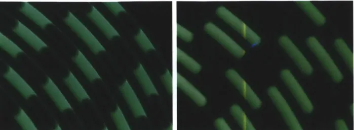
Figure 4.12 - Still images of a thermomorphic transition of DMF-heptane from a single phase to two phases under flow conditions. ... 108
Figure 4.13 - Still images of a thermomorphic transition of DMF-heptane from two phases to a single phase under flow conditions ... 108
Figure 4.14 - Schematic of thermomorphic transitions in confined channels. ... 108
Figure 4.15 - Ternary schematic of overlapping T-x diagrams that change as a function of tem p erature. ... 109
Figure 4.16 - Ternary diagram of water-ethanol-heptane. . ... 110
Figure 4.17 - Effect of composition on DMF-heptane-dioxane ternary system. ... 111
Figure 4.17 - Effect of composition on DMSO-heptane-toluene ternary system. ... 112
Figure 4.19 - Effect of composition on ethylene glycol-toluene-dioxane ternary system... 112
Figure 4.20 - Effect of composition on aqueous-alcohol-alcohol ternary systems... 113
Figure 4.21 - Effect of composition on water-ethyl acetate ternary systems... 114
Figure Figure Figure Figure 5.1 - Fluorous solid phase extraction of dyes. ... 120
5.2 - M icrofabricated packed bed reactors. ... 122
5.3 - Rendering of packaging chuck with labeled components... 123
5.4 - Secondary weir of glass beads for immobilization of particles smaller than 25 p m . ... 12 3 Figure 5.5 - Microfabricated bed loaded with catalytic polystyrene beads. ... 125
Figure 5.6 - Retention of fluorous-tagged phosphine oxide derivatives in methanol, hexanol, and DM SO. ... 127
Figure 5.7 - Switching experiment of fluorous-tagged phosphine oxide in water and D M S O ... 12 7 Figure 5.8 - Correlation of solvent fluorophilicity and polarity... 129
Figure 5.9 - Catalyst loading technique using flow. ... 130
Figure 5.10 - Thermogravimetric analysis of fluorous silica gel technique with different catalyst loadings... 132
Figure 5.11 - Comparison of particle size distribution measurements of FSG using a
Coulter counter and laser diffraction. ... 133
Figure 5.12 - Racem ic fluorous salen(III) catalyst... 134
Figure 5.13 - Ring opening of epoxyhexane with water in the presence of Co-salen(III) cataly sts... 13 5 Figure 5.14 - Fluorous salen stability (left) and activity (right) plots for the ring opening of epoxyhexane (0.07 M ) in heptane... 136
Figure 5.15 - Comparison of conversion between 0.07 M and 1.0 M feeds of epoxyhexane. .. 136
Figure 5.16 - Long term catalyst stability study using 1.0 M epoxyhexane in water.. ... 137
Figure 5.17 - Catalyst recycling using two beds in series... 139
Figure 5.18 - Catalyst recycling using two beds and a 10-port 2-position valve... 139
Figure 5.19 - Characterization of multiple beds in series for retaining material. ... 140
Figure 5.20 - Standard Hoveyda-Grubbs catalyst and fluorous-tagged Hoveyda-Grubbs cataly sts... 14 1 Figure 5.21 - Model ring closing methathesis reaction... 141
Figure 5.22 - Calibration curves for the metathesis reaction. ... 142
Figure 5.23 - Initial activity study of N Ts... 143
Figure 5.24 - Stability study of NTs in different solvents at a two minute residence time. ... 144
Figure 5.25 - Effect of catalyst loading on conversion and deactivation profiles... 144
Figure 5.26 - Beds in series experiment to study metathesis loss of activity... 145
Figure 5.27 - Deactivation profiles under 5 psi and 75 back pressure... 146
Figure 5.28 - Removal of ethylene did little to stem catalyst deactivation... 147
Figure 5.29 - Literature results for a covalently grafted metathesis catalyst. ... 148
Figure 6.1 - Schematic of chromatographic separations with pulse inputs... 151
Figure 6.2 - Schematic of concentration wave fronts under ideal adsorption conditions... 155
Figure 6.3 - Concentration enhancement of A relative to B when A adsorbs but B does n o t. ... 15 6 Figure 6.4 - Concentration wave fronts in adsorption reactors show accelerated . breakthrough in the "mass transfer zone."... 157
Figure 6.5 - Conversion of NTs using a fluorous tagged catalyst with periodic feed stream s of hom ogeneous catalyst. ... 160
Figure 6.6 - Conversion of NTs using a fluorous tagged catalyst with continuous inputs. ... 161 Figure 6.7 -Breakthrough curves of the standard Hoveyda-Grubbs catalyst (HGLO) and
monfluorinated Hoveyda-Grubbs catalyst (HGLl) through a packed bed of
stainless steel beads ... 163
Figure 6.8 -Breakthrough curves of the standard Hoveyda-Grubbs catalyst (HGLO)
through a packed bed of fluorous silica gel... 164 Figure 6.9 - Breakthrough curves of the tosylamide at 1164 cm-1... . .... .. .. .... .. .. .. . 164
Figure 6.10 - Scandium catalyzed Diels Alder annulation of cyclohexadiene and methyl
v in yl k etone... 165
Figure 6.11 - GC calibration curve of the product and dodecane... 166
Figure 6.12 - Deactivation studies at -= 13 minutes (left) and -= 5 minutes (right). ... 166 Figure 6.13 - Deactivation studies with 16 volumetric equivalents of blank fluorous silica
gel to capture eluted catalyst... 167
Figure 6.14 - Increasing yield as a function of time due to accumulation of the catalyst
w ithin the reactor. ... 168
Figure 6.15 - Conversion and product distributions for a series-parallel reaction system at
feed ratios of A:B of 1:1 and 5:1 with initial concentration of B of 1 M. ... 170 Figure 6.16 - Conversion and product distributions for a equilibrium reaction at feed ratios
of A:B of 1:1 and 5:1 with initial concentration of B of 1 M... 170
Figure 6.17 - Comparison of traditional recycle loop and selective adsorption reactor for
List of Tables
15-20
Table 1.1 - Selected efficient Pd-catalyzed reactions for joining large moleculesi-... 21
Table 2.1 - Comparison of dispersion coefficients for multiphase RTDs of silicon and PTFE coated m icroreactors... 57
Table 3.1 - Comparison of conversions and species concentration gradients at 40 seconds and 60 seconds at different Damk6hler numbers... 72
Table 3.2 - Comparison of apparent and actual initial rate constants from simulations... 74
Table 3.3 - Approximate values of X for various kinetic models at 95% conversion... 77
Table 3.4 - Critical values of the Fourier number and X for evaluating the impact of dispersion and mixing on a flow system ... 78
Table 3.5 - Comparison of reactor performance for a glycosylation reaction at different tub e diam eters... 79
Table 3.6 - Conversion at 10 s residence time using different mixing schemes... 81
Table 4.1 - Heptane(1)-DMF(2) parameters for UNIQUAC simulations 180-182 ... 94
Table 4.2 - List of synthetically useful solvents investigated for thermomorphic ap p lication s. ... 94
Table 4.3 - Predicted binary thermomorphic solvent combinations using UNIFAC... 101
Table 4.4 - Predicted biphasic solvent combinations using UNIFAC. ... 103
Table 4.5 - Comparison of CSTs for UNIFAC and experimental results... 105
Table 4.6 - Selected physical parameters of solvents used in this study... 109
Table 4.7 - Composition of water-ethanol-heptane ternary mixtures. ... 110
Table 5.1 - Experimental NCE of fluorous-tagged phosphine oxide in characteristic so lv en ts. ... 12 8 Table 5.2 - Reported physical properties of FluoroFlash Silica Gel... 131
Table 5.3 - Comparison of fluorous platform and covalently grafted catalyst platforms for studying immobilized methathesis catalysts. ... 148
Table 6.1 - Selected solutions to equation 6.16 and error from estimating (= a). ... 158
Table 6.2 - Comparison of catalyst performance under continuous flow selective ad sorp tion ... 162
Ch 1. Background, motivation, and objectives
1.1 Importance and fundamentals of catalytic processes
Some of the most important technological advances of the 20th century were catalytic processes for large scale fuel and commodity chemical synthesis. Since the discovery of the Haber-Bosch process in 19091, the catalytic fixation of nitrogen and hydrogen to produce ammonia has enabled worldwide production of low cost fertilizers. Fluidized catalytic cracking, a widely used process to break apart long chain alkanes, was developed in the 1940s and is responsible for production of a significant fraction of the world's gasoline2. The development of Ziegler-Nata3,4 and related catalysts for the bulk production of polymers in the second half of the
twentieth century has enabled numerous advances ranging from lighter planes and cars to cheap soda bottles. These advances, and numerous others, highlight the impact catalysis has made on the modem world.
Catalytic processes work either by directly lowering the activation energy of a reaction or by enabling alternate pathways to proceed5. As the addition of catalysts directly impacts the kinetic rate, useful metrics to compare catalysts are turnover frequency (TOF) and turnover number
(TON). The turnover frequency is the rate of reaction of generic species A with concentration A
normalized to the catalyst concentration C (equation 1.1), whereas the turnover number is the amount of product formed normalized to the amount of catalyst (equation 1.2). The two relationships are related by either differentiation or integrating (equation 1.3). An erroneous manner in which the turnover frequency is frequently reported is by dividing the TON by the total reaction time, which neglects the rate dependence. Also worth consideration is whether a
the value reported may be slightly different in the case of unwanted side reactions; a TON or TOF based on yield should be preferred.
TOF= mol reacted 1 dA
mol catalyst * unit time C dt
TON = mol reacted (1.2)
mol catalyst
TON = TOFdt (1.3)
0
Catalytic processes are also extremely important for the production of fine and pharmaceutical products. In addition to enabling a wide range of reactions necessary to create complex molecules, several important catalytic reactions facilitate convergent syntheses6, which is an important strategy to augment the yields of molecules requiring multiple steps7-9. Many of the most common and important catalytic reactions for joining complex fragments rely on palladium; selected reactions appear in Table 1.1.
Despite being so important to the fine and pharmaceutical industry, catalytic processes also pose problems. Depending on the chemical reaction and catalyst being used, the cost of the ligand or catalyst can represent a significant fraction of the total catalyst cost. Furthermore, metal contamination is critically important in pharmaceutical products, with acceptable metal contents as low as 5 ppm'0. These factors may necessitate costly separation steps to remove residual metals. Traditional aqueous workups and column chromatography may be sufficient for bench scale purifications; however, use of distillations' , multi-step extractions 1 , or the addition of solid sorbents, either by addition of particulates to a batch of material10' 13 or through
fixed bed adsorption , may be necessary at production scales. Considerations of these factors
indicate that the use of immobilized catalyst systems to reduce both catalyst consumption and product impurity profiles are attractive processing techniques.
Table 1.1 - Selected efficient Pd-catalyzed reactions for joining large molecules1s20
Name Characteristic reaction
B(OH)2 Br Suzuki-Miyaura N N -2 Nr coupling Sn(n-Bu)3 CI N
0K
ZnBr NH20
N/ CO2Me NII CI MeO C1 F3C CI NC CO2Me NI OMe HN , ,CF 3 Ph CN1.2 Traditional catalyst immobilization techniques
Perhaps the most common technique for catalyst immobilization involves covalent attachment of a catalyst to a support. Numerous catalysts, with applications ranging from
21 22
polymerizations21 to the selective reduction of ketones , have been successfully developed using
these schemes (Figure 1.1). While the permanence of this approach to catalyst immobilization is attractive, significant disadvantages include the additional complexity of catalyst preparation23
24
and potential mass transfer limitations to sites located within pores .Furthermore, deactivated Stille cross coupling Negishi coupling Buchwald amination Heck reaction Sonogashira coupling
catalysts can be difficult to regenerate, should regeneration even be possible. Well designed heterogeneous catalysts remains an active area of research that will no doubt see continued interest in the future2 5 27. Immobilization of catalysts on heterogeneous supports can also occur
through non-covalent means; an overview of these techniques is presented in chapter 5 of this thesis.
Transfer hydrogenations Cross-couplings Polymerizations
- -~ R
PS O ArN Z N' Ar
SN NH PR2 C3H6SC3H6
K)
Silica \ 1-H1 H
o
R=Cy, tBu SilicaPAr Ar\N
I 1PR2
CN
NIi
--NH 'NH2 2NrA
O R=Cy, tBu A
Figure 1.1 - Selected examples of heterogeneous catalyst immobilization using covalent attachment. Top: Covalently grafted catalysts1' 2. Bottom: Originally reported homogeneous catalyst29-31
PS: polystyrene, Cy: cyclohexane, tBu: tert-butyl, and Ar: 2,6-diisopropyl benzene.
Immobilization of homogeneous catalysts can be realized by the addition of a phase selective moiety and operation under biphasic conditions3 2, 33. Catalyst recovery can be achieved by
simple liquid-liquid separations, and recycle can be implemented by addition of fresh substrate. This technique thus trades mass transfer resistance from a homogeneous liquid to a heterogeneous site for interfacial mass transfer resistance. The most common example of phase
selective catalyst immobilization involves use of sulphonated phosphine ligands3 2
, 33, though
poly(ethylene glycol)34, fluorous tags"-3, and ionic liquids38 have also been used. A recent
development in biphasic catalyst recovery involves the use of thermomorphic processes9' 40.
These processes use solvent combinations which undergo temperature dependent phase changes to enable homogeneous processing conditions while retaining the ability to separate and recover catalysts under biphasic conditions.
Mechanistic understanding of catalytic processes is important for understanding whether catalyst immobilization will be an effective strategy. Numerous studies using Pd-nanoparticles to catalyze Suzuki444 and Heck45-48 reactions are published nearly every year, despite strong evidence that the catalytic activity in these systems is from leached palladium49-5 2. Our own brief foray into this area demonstrated no advantage for using nanoparticles for a Heck reaction (Figure 1.2). 1.5 M NObMPId O ~0.05 mo1% Pds''' I M 1-5 M 100 80P 60 -=-Pd2 (dba)3 --- Rod particles R t - Spherical particles e 40-20 0 50 100 150 200 260 300 3 Time - min
Figure 1.2 - Comparison of homogeneous and heterogeneous Pd-sources at 0.05 mol% loading for the Heck reaction of 4-iodo methoxybenzene with ethylacrylate. Nanoparticles were prepared by Dr. Victor Cabeza of the Jensen group.
While full conversion was achieved in all cases using 0.05 mol% Pd (TON: 2000), conversion took significantly longer when using the nanoparticles compared to standard
commercially available palladium sources, such as palladium diacetate (Pd(OAc)2) or
tris(dibenzylideneacetone) dipalladium(0) (Pd2(dba)3). The induction period when Pd2(dba)3 was
used corresponds to dissociation of free Pd(0) from the stabilizing dibenylideneacetone ligand. Similarly, the induction period when using the nanoparticles indicates in situ catalyst formation
from the heterogeneous Pd-source was rate limiting. This study demonstrates immobilization of Pd-nanoparticles on a heterogeneous support would not be an effective technique.
1.3
Microreactors for studying catalytic processes
tThe advantages of microreactors for studying flow chemistry are well documented- . These devices have characteristic dimensions of <1 mm but are more typically within 50-500 micron; the small length scales enable both rapid diffusion-based mixing 8'59 and high interfacial areas for multi-phase applications60. Microfluidic devices can be made of low cost capillary tubes and HPLC fittings; however, significantly more complex devices containing integrated
valves61-63 PUMPS64' 65, and separations '7 can be made from silicon 6, stainless steel69 ceramics70'71, glass7 2, poly(dimethyl siloxane)62,73-75 or poly(tetrafluoroethylene)76 (Figure 1.3).
Spipette
loading
Inlet outlet
Figure 1.3 - Complex integrated microfluidic devices. Top left: Onchip multistep synthesis of radiolabeled imaging probes65. Top right: Integrated formulator for protein crystallization screening63 Bottom: SlipChip for combinatorial screening".
Material of construction plays a large role in the characteristics of a microreactor.
Microreactors with high heat conductivity, such as those made from silicon or ceramics, facilitate both extremely exothermic reactions and reactions requiring high temperatures78' 79.
The small thermal mass of the fluidic elements enables near instantaneous heating and cooling;
* Themes from this section appear in "Catalytic processes in small scale flow reactors: Status and opportunities," Chimica Oggi/Chemistry Today, 2011, 29 (4) 18-21.
temperature drops > 200*C have been achieved over the distance of only a few millimeters using
so-called "halo etch" microreactors (Figure 1.4)80.
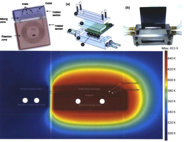
Ioutle (a) (b) zom COK Ma:: 455 K 20 K 300 K 380 K 360 K 340 K 320K 300 K Min: 285 K
Figure 1.4 - Halo-etched reactors enable high temperature-high pressure reactions. Top left: Reactor schematic81. Top middle: Chip holder schematic8 0 Top right: Photograph of packaged device80. Bottom: Steady state temperature profile obtained using COMSOL 3.282.
Several microreactor designs allow operating pressures up to hundreds of bar72' 80, 83 The
combination of these properties enable reactions at extreme conditions6 9, such as the epoxide
aminolysis in THF at 195*C82
,84 and nanoparticle formation in supercritical solvents8 5,8 6
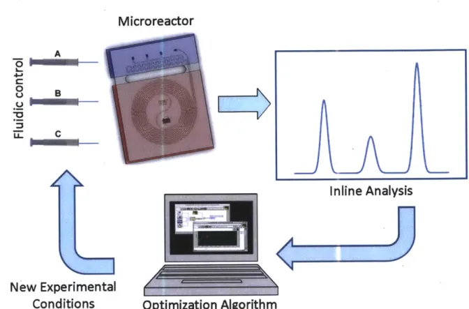
Continuous flow operation and small volumes enable numerous experiments to be carried out quickly and using small volumes of material; a kinetic study comprising >100 experiments was performed by a single researcher in <24 hours82. Computer controlled platforms coupled with inline analytics and feedback algorithms offer the potential to screen many reactions87
optimize chemical processes without user input* , and rapidly obtain kinetic data using
minimal amounts of material (Figure 1.5)92.
Microreactor
A Cir
c
Inline Analysis
New Experimental
Conditions
Optimization Algorithm
Figure 1.5 - Auotomated experimentation represents some of the most promising applications for microfluidics.
The development of continuous separations using surface forces for multi-phase liquid-liquid and gas-liquid systems has enabled multi-step chemical transformations93-95. Compared to the initial designs where fluid was contacted across microfabricated capillaries96, the development of selective wetting membranes allows for higher throughputs and the potential to scale beyond the microscale 66. Furthermore, as these separations operate on the basis of differential pressure across the membrane, gas-liquid and liquid-liquid separations at high pressure can be achieved 7. As the development of new catalytic processes continues, the ability to rapidly screen numerous reaction conditions using minimal amounts of material will be attractive. An overview
1.3.1 Homogeneous liquid phase processes
Microreactors coupled with inline analytics are ideal for performing high throughput catalyst screening and optimization due to the small catalyst quantities consumed during these processes. Weber and co-workers recently screened the activity of 18 different acid catalysts using 2.4 ptg of material per experiment7. Inline UPLC was used for reaction monitoring, and the authors claimed studies using nanograms of materials were feasible.
McMullen and Jensen have developed a similar self optimizing platform and demonstrated the selective oxidation of benzyl alcohol to benzaldehyde using a chromium catalyst and a palladium catalyzed Heck reaction of a deactivated aryl chloride and alkene90' 91. The optimized experimental conditions for the Heck reaction could be directly scaled 50x to a meso-reactor with nearly identical performance. Most previous studies have observed that the throughput limiting step in these platforms is typically the analytical equipment, as the use of chromatographic separations introduces additional time delays in the system. Quantitative inline analytical techniques that do not require separation, such as in-line FTIR98 and flow NMR99,
should enable increased experimental throughput.
The ability to precisely control fluid contacting time in continuous flow systems enables catalytic transformations of unstable species. Yoshida and co-workers have developed a number of reactions in this vein57. A recent example involved a sequential lithium-halide exchange
reaction followed by a PEPPSI catalyzed Murahashi coupling reaction (Figure 1.6) 100. The lithium-halide exchange, normally done at -78'C in batch, was complete in 2.6 seconds at room temperature, and the cross coupling results for several species gave good to excellent yields in 94 s at 50 'C with 5 mol% catalyst. Use of 1 mol% catalyst with p-bromoanisole resulted in significantly reduced yields (18% vs 93%) and significant amounts of a side product,
butylmethoxybenzene, which highlights the challenge of working with such unstable intermediates. Br Li Ph . ~ PEPPSI-SiPR BuLi '~Bromobenzene 0 *C, 2.6 s 50 *C, 94 s
OMe OMe OMe
Figure 1.6 - Murahashi cross coupling achieved using continuous flow technology.
1.3.2 Multi-phase liquid-liquid and gas-liquid catalytic processes
Continuous flow technology is excellent for studying high pressure gas-liquid reactions that are difficult or hazardous to run in batch. Furthermore, the high interfacial area makes microfluidic devices excellent tools for studying multi-phase chemistry. Gas-liquid mass transfer coefficients as high as 8.0 s-1 have been achieved0 1, which is two orders of magnitude higher than batch or semi-batch reactors02. In addition to reaction acceleration, increased mass
transfer can change reaction selectivity, as demonstrated by the enhanced formation of oa-ketoamide in a Pd-Xantphos catalyzed aminocarbonylation reaction at elevated pressures in flow systems compared to batch'0 3.
An interesting example highlighting many of these advantages comes from Stahl's group, which in collaboration with Eli Lilly, recently developed a scalable protocol for the oxidation of secondary alcohols to ketones and aldehydes using a palladium catalyst and oxygen (Figure
1.7)104. The reaction time was reduced from 18 hours in batch to 45 minutes in a 5 mL (0.25"
OD) tubular steel reactor under flow conditions using 30 psia oxygen. Furthermore, enhanced
mixing in the flow system reduced the formation of palladium black, which was problematic in batch operations. Scale-up of 10 compounds at flow rates of 54 mmol substrate per hour using
~5% 02 at a total pressure of 500 psi was achieved in a 400 mL (0.5" OD) tubular reactor. The oxidation of 1 -phenylethanol to acetophenone was demonstrated in a 7 L (0.3 75" ID) reactor at a
kilogram scale in near quantitative yield. Notably the residence times reported increased with scale - 45 minutes in the 5 mL reactor, 2.5 hours in the 400 mL reactor, and 4.5 hours in the 7 L reactor, though the authors stated direct scale-up by two orders of magnitude from the 7 L reactor was possible. The reduced space time yields are a direct result of reduced mass transfer at larger length scales and highlight the challenge of scaling multi-phase continuous flow processes.
OH 02, 30 psi 0
Pyridine
Pd(OAc)2
Figure 1.7 - Pd-catalyzed oxidations of secondary alcohols to ketones under continuous flow conditions at a total system pressure of 500 psi104.
Continuous flow catalyst recycling has recently been accomplished using molecular weight enlarged (MWE) catalysts in conjunction with nanofiltration membranes'0 . A MWE
triphenylphosphine derived catalyst was used in the hydroformylation of 1 -octene, such that the substrate and product permeated the ceramic membrane but the metal-ligand complex was retained. The catalyst containing retentate was recycled for nearly 2 weeks before significant catalyst deactivation was observed, and a turnover number of 120,000 was achieved. The major disadvantage of nanofiltration is the high operating pressures required to force material through the nanofiltration membrane, though in this example, the separation pressure corresponded to the operating pressure.
In the case of liquid-liquid systems, use of phase selective ligands enable downstream separation and catalyst recycling, though surprisingly little work on catalyst recycling has been reported using continuous flow technology. Two such examples involve recycling palladium catalysts. Huck and Wootton performed Pd-catalyzed Suzuki couplings of aryl boronic acids and aryl bromides using a fluorous-aqueous system with a fluorinated guanidine ligand106. The
catalyst was continuously recycled for three "cycles" with less than 2% Pd loss into the product. Early work by the Ryu group performed a solvent free Heck reaction using a low viscosity ionic liquid10 7. The catalyst containing ionic liquid was continuously recycled ~5 "cycles" over 11.5
hours, which produced ca. 10 g/hour of butyl cinnamate in a 15 mL CYTOS CPC lab system. Continuous product and salt extractions were performed with good retention of the catalyst in the ionic liquid phase. In both of these cases, separations were accomplished via gravitational settling, and catalyst recycling was performed with an inline pump. The micro scale separations using capillary forces previously mentioned would have reduced holdup compared to the mL
scale settling tanks used in these examples96
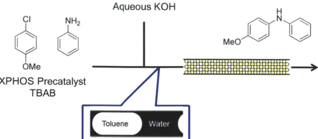
Organic-aqueous biphasic systems also enable flow processes for reactions that generate inorganic salt byproducts. Naber and Buchwald found that efficient mass transfer was critical in both batch and continuous Pd-catalyzed amination reactions of aryl chlorides and aryl amines'08.
The use of both tetrabutylmmonium bromide as a phase transfer agent and a column packed with stainless steel beads were necessary to achieve high yields (Figure 1.8). Performing the reaction in capillary tubing or without a phase transfer catalyst resulted in significantly reduced yields. Furthermore, the use of different volume packed beds at a constant residence time demonstrated that either the mass transfer or hydrodynamics within the reactor were critical, as faster linear velocities resulted in improved yields. This technique has since been extended to Suzuki
94
Aqueous KOH H CI NH2
CK
N
MeO
N
OMe XPHOS Precatalyst TBABFigure 1.8 - Use of packed beds comprising stainless steel beads was found -to accelerate biphasic Pd-catalyzed amination reactions 108.
1.3.3 Solid supported catalytic processes
The most common reactor design for solid supported systems is a fixed bed, where porous catalyst particles are retained in a chamber and the reaction solution passes over it. High catalyst loadings per unit volume may be achieved, which result in reduced residence times. Downstream purification steps to remove catalyst from the product are unnecessary, and unlike biphasic systems, liquid-liquid separations and pumps are not required for catalyst separation and recycle. Our group has developed a number of silicon devices that enable visual access'09~112 for
applications ranging from phosgene synthesis1 3 to kinetic analysis of hydrogenation catalysts97
(Figure 1.9).
A number of other research groups beyond our own have also investigated fixed bed reactors
for catalytic processes 1 4. The commercial supplier Thales-Nano offers a number of catalyst
cartridges for its H-cube platform; however, the company's main focus remains hydrogenations 15, 116. The Ley group has performed a number of Pd-catalyzed reactions using
heterogeneous palladium sources'119, though these reactions likely occur through
homogeneous mechanisms as discussed in section 1.2. Monolithic supports developed by Andreas Kirschning120, 121 and others m offer an alternative to either silica or polymer bead
Solid liquid catalytic systems suffer from a number of challenges at the microscale. Common polymeric supports, such as Merrifeld resins, can swell in organic solvents. Swelling can potentially reduce access to catalytic sites while increasing pressure drop and can even cause brittle reactors, such as those made from glass or silicon, to fail. Furthermore, the smaller interstitial path lengths in packed beds prohibit reactions that produce solids, as sonication and other techniques to control particle growth and deposition are ineffective124, 125. Lastly, solid
supported catalysts that operate through so-called "boomerang" mechanisms, where the active species desorbs from the support under reaction conditions and re-adsorbs upon completion of the reaction, are poorly suited to flow conditions.
Figure 1.9 - Microfabricated devices for studying supported catalysts. From left clockwise: High pressure gas-solid reactor'09. Gas-liquid-solid trickle bed reactor'0 9. Gas-liquid trickle bed reactor". Parallel packed bed with integrated temperature sensors"2. Porous silicon posts"0. Cross flow packed bed"'.
The high surface area to volume ratio of microreactor systems offers the ability to immobilize catalysts in other manners besides on beads. Impregnating microstructured
11 126, 127
features"0 or even directly coating the surface of capillary tubing may be effective .2, In certain cases, reactors can even be made of the catalytic material, as demonstrated by Bogdan and Sachs, who used copper tubing to catalyze azide-alkyne click reactions and synthesized a library of 30 triazoles in a few hours12 8. The major advantage of these techniques compared to
packed beds is -increased heat removal, as the amount of catalyst per reactor volume is significantly lower. Results obtained in these types of reactors will be challenging to scale as demonstrated below.
For capillary tubing, the surface area to volume ratio can be calculated by dividing the tube diameter by 4. Thus, 500 micron diameter ID capillary tubing has 8,000 m2/m3, whereas 1 mm
diameter ID tubing only has 4,000 m2/m3. Conversely, the surface area to volume ratio in
packed beds is determined as the product of the bulk density and surface area per mass. Commercially available silica gel has a bulk density of -700 kg/m3 and surface area ranging from 450 to 600 m2/g, giving a surface area to volume ratio of 3.1-4.2x10⁸ m2/m3, a factor of 40,000-200,000 larger than surface coatings. Considering the surface area to volume ratio of non-porous 50 micron beads is 60,000 m2/m3, even low surface area supports will outperform
surface coated tubes. Furthermore, the surface area to volume ratio of packed beds does not change as a function of bed diameter. While catalytic surface coatings will continue to be important for extremely exothermic reactions, such as combustion, their practical use in liquid phase organic transformations is limited for most industrial applications.
1.4 Specific thesis objectives and outline
Due to the importance of both catalytic and continuous flow processes for organic syntheses, the evaluation and implementation of novel catalyst immobilization techniques under flow conditions was the primary goal of this thesis. The secondary aim of the thesis was to extend the utility of microreactor technology for chemical synthesis applications. These results are presented in reverse order; the first portion of the thesis comprises fundamental studies in residence time distributions, dispersion, and mixing relevant to microreactor platforms, and the second half of the thesis evaluates thermomorphic processes and physical adsorption techniques
for catalyst immobilization and recycle. The penultimate chapter describes a new concept for augment homogeneous catalytic processes through the use of continuous flow selective adsorption reactors. The last chapter summarizes the major contributions of the work
Development of a means to evaluate catalyst retention under physical adsorption techniques was necessary, and inline UV-vis spectroscopy was identified as a suitable technique. The application of this platform to characterize flow patterns in single-phase- liquid, multi-phase liquid-liquid, and multi-phase gas-liquid flows is discussed in chapter two of this thesis.
A summary of dispersion and mixing effects in flow systems is presented in chapter three of
the thesis. These effects can have a significant impact on reactor behavior, and the ability to quickly identify the relative impact of each parameter on a flow system is presented. Both effects can be calculated using a system Fourier number, which is the ratio of the residence time in a flow system to the characteristic tranverse diffusion time. The techniques outlined in the chapter are demonstrated to improve throughput and selectivity of a previously reported
129
glycosylation reaction
The evaluation of thermomorphic processes as potential immobilization techniques for flow systems is the focus of chapter four. A major limitation to the technique was identified as an insufficient number of known synthetically useful solvents that display thermomorphic behavior.
A screening program was written to predict new solvent combinations using activity coefficient
models. The simulation resulted in the identification of several new thermomorphic solvent combinations, including ternary systems with tunable critical solution temperatures. Consideration of the limitations of thermomorphic processes is presented, and the technique is ultimately evaluated as being too constrained to serve as a general technique for catalyst immobilization and recycle under flow conditions.
Investigation of fluorous physisorption as an immobilization technique under flow conditions is presented in chapter five of this thesis. The successful application of a fluorous-tagged salen catalyst to effect the ring opening of epoxides demonstrated the utility of the immobilization technique. The application of the platform to a fluorous-tagged metathesis catalyst resulted in loss of activity over time, which was determined to be from catalyst deactivation and not elution.
A novel catalyst recycling scheme for these types of systems is also presented.
A proposed model for enhancing catalytic processes through the use of selective adsorption
reactors is the focus of chapter six. The use of phase tagged catalysts in conjunction with adsorption beds is demonstrated to augment catalyst performance due to accumulation of the catalyst on the adsorbent bed. The technique is demonstrated using a fluorous-tagged Lewis acid catalyst to effect a Diels-Alder reaction with TOF enhancement of an order of magnitude compared to batch results. A second application to the fluorous-tagged metathesis catalysts presented in chapter five resulted in significantly enhanced behavior and the surprising discovery that non-fluorous tagged catalysts can also adsorb on fluorous supports. A mathematical model of the system is presented, as well as the potential advantages and limitations of the technique.
The major research contributions of this thesis are summarized in chapter seven, and comments on the future outlook for the field are presented.
Ch 2. A general platform for characterizing single-phase
and multi-phase residence time distributions
2.1 Motivation
Choice of reactor model can have a large impact on chemical conversion within a flow system. The two extremes of flow reactor geometries are the continuous stirred tanked reactor (CSTR) and the plug flow reactor (PFR). Kinetic models for CSTR come from performing a macroscopic mass balance around the reactor and neglect mixing effects; the operating condition for a CSTR is assumed to be the outlet concentration. Conversely, kinetic models for plug flow reactors are derived- through a shell balance, which results in axial concentration gradients and conversion as a function of length or residence time. The kinetic model for a plug flow reactor in the absence of volume changes is mathematically identical to a batch reactor. Both CSTRs and PFRs are advantageous for specific reaction types; as CSTRs operate at the outlet concentration, negative order reaction models proceed most quickly, whereas positive order reactions proceed more slowly. Conversely, the higher inlet concentrations make PFRs advantageous for positive order reactions. As most liquid phase organic transformations display positive order dependencies on concentration, the PFR model represents a desirable reactor type for flow processes.
In reality, different combinations of reactor configurations exist; multiple CSTRs in series can provide a reasonable approximation of PFR behavior, which can be useful for reactions that generate solids. Conversely, tubular flow reactors can deviate from plug flow behavior at low Reynolds numbers due to a parabolic velocity profile. Other potential causes of deviations from plug flow arise from maldistribution of flow through poorly packed fixed bed reactors, recirculation eddies due to geometry changes, or entrance and exit effects. Quantifying the
deviation from plug flow is important and has been generally termed dispersion; dispersion effects can adversely affect both conversion and reaction selectivity.
A technique for characterizing the flow profile through a reactor involves performing
residence time distribution (RTD) measurements24, 130. This technique allows facile comparison
between different reactor geometries and configurations and enables determination of the magnitude of deviation from plug flow behavior. This chapter outlines a general platform that has been used for single phase and multi-phase RTDs and includes the physical setup and theory used to analyze experimental results.
2.2
Review of theory of residence time distributions
Residence time theory is closely tied to the analysis of dispersion coefficients performed by Taylor and Aris in the 1950s131, 132. The key transformation to arrive at the dispersion model
involves a change of coordinates in the convection-diffusion model for fluid flowing through a tube from a stationary tube (equation 2.1) to a stationary mean fluid center point (equation 2.2). The transformed continuity equation appears in equation 2.3.
dC d2C dC = D - u -- (2.1)
dt
dx2dx
t ut+x 0 = - and z = (2.2) r L dC D d2C dC (2.3) dO uL dz2 dzThese studies predict the spreading of a tracer in a fluid system as a function of a dispersion coefficient, D, which is a function of diffusion, D, mean fluid velocity, U-, and tube diameter, dt (equation 2.4)33. While the concept of residence time distributions is broad, the dispersion model is primarily applicable to flow through tubes or channels.
D = D+ d (2.4)
Two common techniques for performing RTD analysis of a flow system involve either injecting a pulse of tracer into a flow system or creating a step change in concentration. For a pulse injection, a tracer is injected into a carrier stream, and the response of the tracer is monitored after the reactor. Step change experiments operate by instantaneously switching the inlet feed concentration of a tracer and monitoring the dynamics until steady state has been achieved (Figure 2.1). For systems with significant dead volume between the reactor and tracers, measurements of the tracer form and deconvolution are necessary to assess the residence time distribution of just the reactor.
C 0 C C 0
Time
Figure 2.1 - Pulse injections (left) and step change (right) experiments for performing residence
time distribution experiments. The blue line represents the change to inlet conditions, and the red line represents the system response.
The mean residence time, r, and variance, o2, for tubular reactors treated using the dispersion model are linked to the first and second moments to the solution of equation 2.3, respectively. For a hypothetical pulse injection, the mean residence time appears in equation 2.5, and the variance appears in equation 2.6.
ftC
(t)dt r 0 (2.5)fC (t)
dt
0ft
2c(t)
dt
a7 = 0 -r2 (2.6)JC(t)dt
0While some conflicting definitions exist in the literature about the definition of the Bodenstein number (Bo), we have chosen to define Bo as the ratio of convection to dispersion
(equation 2.7) and the Peclet (Pe) number as the ratio of convection to diffusion (equation 2.8).
Bo = (2.7)
D
Pe = -L (2.8)
D
For systems where the Bodenstein number is greater than 100, spreading of an idealized pulse injection may be represented by a Gaussian approximation (equation 2.9). As spreading of the tracer occurs about the mean, the non-dimensional time 9 is the ratio of real time, t, normalized to the bulk fluid residence time (equation 2.10). Furthermore, the variance spreads inversely to the Bodenstein number (equation 2.10)134.
Bo
Bo
2C() exp 1 (1-0)1 (2.9)
0=- (2.10)
o22 (2.11)
0 Bo
Normalization of the dimensional concentration C by total tracer quantity results in a convenient comparison between different reactor configurations and tracer systems (equation 2.12). This equation can also be readily written in non-dimensional time, 0, as well. These
curves are frequently referred to as either E curves for pulse injection experiments or F curves for step change experiments24. E and F curves are interchangeable by integration or
differentiation, respectively (equation 2.13). The Bodenstein number can also be simply calculated based on the maximum peak height of the E(O) curve (equation 2.14)24.
E(t) =C(t) .or E((0)= C()
)
(2.12)C
(t)dt
JC(o)dO
0 0 d E(O) =(F
(0))
(2.13)dO
max{E(O)) = (2.14)For systems where the Bodenstein number is less than 100, a dependence on the boundary conditions exists for the form of the mathematical approximations. Two types of boundary conditions are frequently used: 1) closed-closed, and 2) open-open. Closed-closed assume that plug flow (e.g. no velocity profile) exists outside of the region being modeled. Open-open boundary conditions assume a pre-existing fully formed velocity profile exists upon entering and exiting the modeled zone and are easier to model mathematically.'3 0 The entrance length to achieve fully developed flow can be approximated by equation 2.15.133, 135 For a typical
Reynolds number of 0.1-100 and channel width of 500 micron, this entrance length corresponds to 0.5-5.5 mm. Thus, open-open boundary conditions are adequate for microfluidic devices, which typically have lengths significantly longer than the hydraulic diameter.
Letrance 1 + 0.1 Re (2.15)
d,
Near Gaussian forms can still be used for these smaller Bodenstein number systems (equation 2.16), though a second order expansion is necessary to calculate the variance (equation