HAL Id: hal-02515331
https://hal.archives-ouvertes.fr/hal-02515331
Submitted on 23 Mar 2020
HAL is a multi-disciplinary open access
archive for the deposit and dissemination of
sci-entific research documents, whether they are
pub-lished or not. The documents may come from
teaching and research institutions in France or
abroad, or from public or private research centers.
L’archive ouverte pluridisciplinaire HAL, est
destinée au dépôt et à la diffusion de documents
scientifiques de niveau recherche, publiés ou non,
émanant des établissements d’enseignement et de
recherche français ou étrangers, des laboratoires
publics ou privés.
An algorithm for generating mechanically sound sphere
packings in geological models
François Bonneau, Luc Scholtes, Hugo Rambure
To cite this version:
François Bonneau, Luc Scholtes, Hugo Rambure. An algorithm for generating mechanically sound
sphere packings in geological models. Computational Particle Mechanics, Springer Verlag, 2020,
�10.1007/s40571-020-00324-7�. �hal-02515331�
(will be inserted by the editor)
An algorithm for generating mechanically sound
sphere packings in geological models
Fran¸cois Bonneau · Luc Scholt`es · Hugo Rambure
Received: date / Accepted: date
Abstract The discrete element method (DEM) is a powerful tool for simulating complex mechanical behaviors which discretizes the targeted medium with parti-cles. The properties of particle assemblies used in DEM simulations directly impact the behavior of the simulated medium. It is thus of critical importance to generate particle assemblies so as to (1) avoid any bias induced by their fabric, and (2) conform with the structural discontinuities of the medium under consideration. The main objective of this work is to propose an algorithm, inspired by the space filling Apollony fractal, to generate sphere packings in geological objects as a first step toward their mechanical modeling with the DEM. In particular, we assess the relevance of the generated packings for simulating the behavior of a rock-like material, and we discuss the ability of the proposed approach to discretize geolog-ical models. The algorithm ensures the tangential conformity of spheres with the model boundaries (internal and external), and enables to adapt the particle size distribution in the vicinity of structures of interest such as, fractures or faults. Keywords Sphere packings · Adaptive refinement · Geological models · Discrete Element Method
1 Introduction
The discrete element method (DEM) is a numerical technique now commonly used for simulating the mechanical behavior of discontinuous media such as soils or rocks [10, 37, 11, 36]. Thanks to its ability to describe large deformations and
F. Bonneau
Universit´e de Lorraine, CNRS, GeoRessources, Nancy, France E-mail: [email protected]
L. Scholt`es
Universit´e de Lorraine, CNRS, GeoRessources, Nancy, France E-mail: [email protected]
H. Rambure
associated fracturing phenomena, the DEM has been successfully applied to study physical processes taking places at different scales in geologic media, such as fault gouge mechanics [31], fracturing in rock masses [38], volcanic eruptions [24], caldera collapses [15], or more general tectonic processes [13, 47].
A DEM model represents the medium under consideration as an assembly of particles interacting with one another following predefined contact laws. The particle assembly, or “packing”, must comply with several geometric requirements to provide accurate simulated behaviors. For geomaterials, and for rock materials in particular, a crucial requirement is that the packing is polydisperse, presents a relatively high density, and has an isotropic structure so as to avoid any bias related to its fabric when subjected to mechanical loading [7, 4, 16]. Numerical solutions has been recently proposed to perform large scale DEM simulations with non-spherical particles [12]. Nonetheless, spherical particle models prevail for simulating the mechanics of geological media due to the simplicity of their formulation as well as to their lesser computational demands compared to non-spherical particle models [37, 15, 13, 24, 47]. As a matter of fact, anyone aiming to simulate a large scale boundary value problem with the DEM needs to go through the necessary step of building sphere packings that conform with the geometry and the mechanical behavior of the medium under consideration.
Many solutions exist for generating dense polydisperse sphere packings in pre-defined volumes. They are usually classified into two categories: dynamic and con-structive. The dynamic approaches consist in running physics-based simulations to generate particle assemblies mechanically in equilibrium. The constructive ap-proaches position particles in space based on pure geometric calculations. Both approaches have advantages and drawbacks but the constructive approaches are generally more efficient and more flexible than the dynamic ones [21, 27].
Dynamic methods are based on three principal mechanical processes to pro-duce dense particle packings: gravitational deposition of particles [41], isotropic compression [43], and particle size expansion [25]. All three processes use New-ton’s second law of motion to determine the trajectories and the final positions of the particles. These processes can be simulated with the DEM. Hence, they can be properly constrained to control the final packing properties if the DEM models are correctly parametrized (e.g., the interparticle friction angle controls the final porosity, the interparticle stiffnesses control the amount of particle overlap). Ac-tually, dynamic methods can produce packings with higher densities than most of the constructive methods. However, generating large scale DEM models can be problematic with respect to the computational effort since a complete DEM simu-lation has to be performed. In such cases, optimization techniques are required [8]. Also, except for the size growing technique, dynamic methods cannot be applied to complex-shaped domains without specific adjustments.
Constructive methods are also known as geometric methods since they rely on mathematical rules to place particles in space. Three main techniques have been proposed for generating random polydisperse packings: mesh- or grid-based methods [9, 22], sedimentation techniques [17], and advancing front approaches [1, 2]. Among these solutions, the mesh-based methods and the advancing front approaches seem to be the most popular. Recently, many works have focused on these two approaches because they can (1) generate high density packings in complex-shaped containers, and (2) consider large amounts of particles [23, 46, 27]. Most of these methods were developed with the aim to perform subsequent DEM
simulations. However, to our knowledge, only few of them have been actually used in DEM simulators [21]. Moreover, there is currently no available method that offers the possibility to explicitly describe discontinuities such as fractures, faults, or stratigraphic horizons which are ubiquitous in geological media.
In this work, we present a geometric-based algorithm inspired by the space fill-ing Apollony fractal to generate polydisperse spherical particle assemblies [3]. The algorithm is an offspring of the Protosphere algorithm [49] which we specifically adapt to generate sphere packings in geological models so as to perform subse-quent DEM simulations. The packings conform to geological structures described through boundary representations [6]. Practically, the spheres are tangent to every structures present in the model so as to ensure an explicit representation of the object boundaries, either the external surface envelope of the model, or its inter-nal discontinuities or cavities. The algorithm also offers the possibility to locally adapt the resolution of the packing in the objective of reducing the total number of spheres in the model while keeping sufficient level of details in areas of interest. In the following, we first present and describe the algorithm we propose to gen-erate sphere packings in boundary representations. Then, we assess the relevance of the generated packings for modeling geomaterials by assessing their mechanical behavior. Finally, we provide examples highlighting the capabilities of the algo-rithm to fill up structurally complex media, emphasizing on its ability to deal with internal boundaries and adaptive refinements.
2 Packing algorithm
The Protosphere algorithm [49] fills up arbitrary domains with polydisperse Apol-lonian sphere packings. We modify it to produce packings suitable for DE modeling of geomaterials.
2.1 The Protosphere algorithm
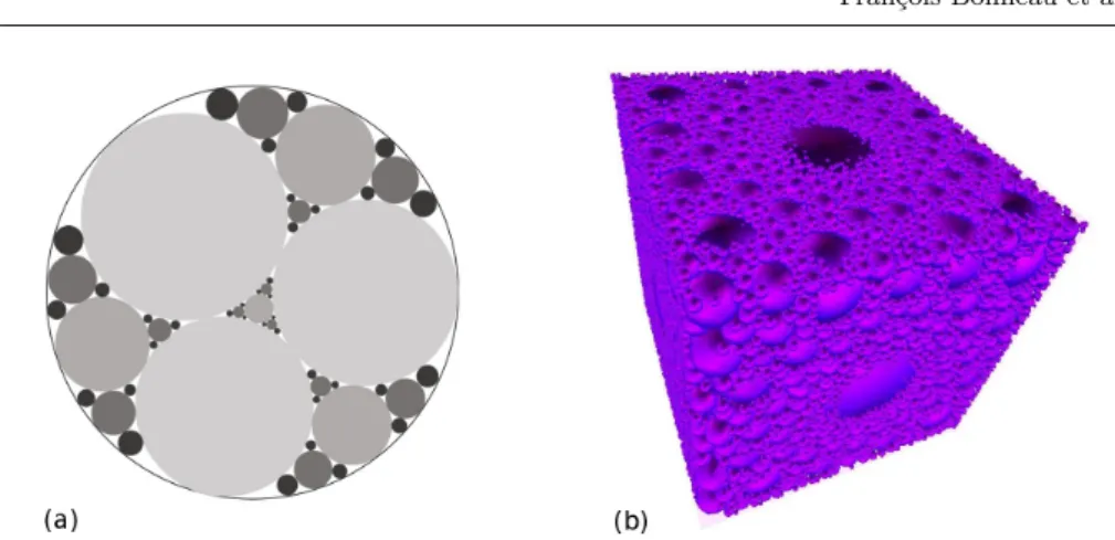
The Protosphere algorithm extends the method of Apollonian sphere packings to arbitrary container objects. Apollonian packings [3] are fractal structures which assemble spheres based on geometrical rules. An example of such packings is the 2D Apollonian gasket presented in Fig. 1 that can be built starting from a circle containing three smaller circles circumscribed inside the bigger one. All subsequent circles are positioned to be tangent to three other circles using the Soddy theorem [48] and the self-similar property of the fractal makes it infinitely space-filling.
The Protosphere algorithm adds spheres in the considered domain following an iterative procedure. First, it randomly picks an initial position for a potential sphere center inside the domain. This position needs to be inside the volume of interest and outside of the spheres previously placed. Then, an optimization pro-cess maximizes the distance between the tested position and the closest boundary, either the domain boundary or the previously embed spheres. In practice, (1) the closest projection of the tested position onto the neighboring boundary is evalu-ated, and (2) a step vector is defined to move the tested position away from this boundary. A cooling function ensures the convergence of this process by reducing the amplitude of the displacement when the number of iterations increases [26]. A
Fig. 1 Apollonian sphere packings: (a) 2D Apollonian gasket where colors correspond to the iteration steps of the filling process and (b) a sphere-filled cube showing the fractal Apollonian property of the Protosphere algorithm (modified from Weller and Zachmann [49]).
sphere is added to the packing when the optimization process has converged. The newly embed sphere center is assigned to that final position. Its radius is directly computed from the distance between its center and the nearest boundary.
The Protosphere algorithm is attractive because it can generate dense sphere packings inside arbitrary shapes. However, due to their fractal property, these packings are certainly not adapted to perform relevant DEM simulations of geo-materials (Fig. 1). Indeed, besides the particle size distribution which would most probably compromise the relevance and representativeness of the material behav-ior by itself, the generated packings present a highly heterogeneous fabric. These packings would produce undesirable bias in DEM simulations as a result of their strong anisotropy, as well as of the spatial distribution of their constitutive parti-cles. For instance, an external load applied on the boundaries of the cube presented in Fig. 1 would be exclusively borne by the biggest central particle of the packing, hence annihilating the purpose of the modeling.
2.2 Enhancement to meet DE modeling requirements
We explain here the modifications and optimizations made on the Protosphere algorithm to produce particle packings suitable for DE modeling of geomaterials. In particular, we describe how to generate spheres with sizes belonging to a user defined size range [rmin, rmax]. Indeed, it is important to be able to control and
limit the size ratio rmax
rmin of the particles in DEM simulations. The polydispersity of
the packing ensures a representative behavior of the simulated medium but the size ratio has an effect on the computational efficiency. In fact, the time step of a DEM simulation is a direct function of the mass of the constitutive particles - i.e., their size. Large particle size ratios tends to increase the computational time needed to reach a given deformation stage as the smallest particles decrease the time step. Moreover, rmaxhas to be carefully chosen as a function of the characteristic length
of the medium to model (e.g., grains, fractures, pores). Indeed, rmaxshould ensure
implanted sphere internal boundary external boundary rmin rmin rmin
Fig. 2 Potential sphere centers have to be inside the volume of interest and outside of the spheres previously embed. To avoid useless convergence steps for centers located in volumes which could not receive spheres belonging to the predefined size range [rmin, rmax], potential
sphere centers cannot be located in the gray areas. The new particle has to be nucleated in the white area.
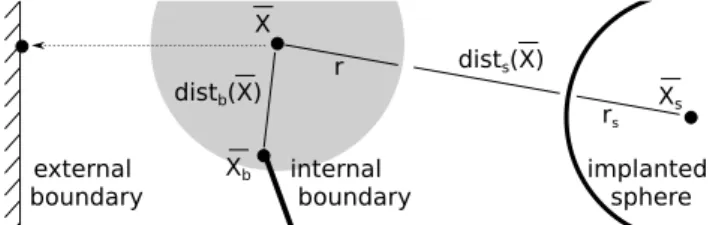
implanted sphere internal boundary external boundary r X Xs rs dists(X) distb(X) Xb
Fig. 3 The optimization process considers two distances: dists( ¯X) (Equation 1) that tends
to be minimized, and distb( ¯X) (Equation 2) that tends to be maximized.
Initial picking of potential sphere centers: The original algorithm randomly picks a sphere center within the volume defined by the domain boundaries, outside of the spheres previously embedded. The modified algorithm rejects positions picked in spaces that are too small to receive the smallest sphere defined by the user through rmin. In other words, every sphere center located too close to either a
sphere or a boundary is rejected (Fig. 2).
Optimizing the positioning of the spheres: Contrary to the original cost function that maximizes the distance between the sphere center and the closest boundary, the positioning of the sphere center ¯X is optimized considering its targeted radius r (Fig. 3). The modified cost function first minimizes the distance dists( ¯X), defined
as:
dists( ¯X) = |||( ¯X − ¯Xs)|| − (rs+ r)|, (1)
with rsand ¯Xsthe radius and the center of the closest neighboring sphere
respec-tively. Then, when the distance to the closest boundary distb( ¯X) is smaller than
r, the cost function maximizes this distance defined as:
distb( ¯X) = ||( ¯X − ¯Xb)||, (2)
with ¯Xb the orthogonal projection of ¯X on the closest boundary.
Setting the sphere sizes: Our algorithm does not allow a complete control of the output sphere size distribution. For instance, it is not possible to reproduce a predefined distribution. Nonetheless, it ensures that the sphere radii belong to the range [rmin, rmax] defined by the user. As mentioned previously, the positioning
the end of the optimization process, if the sphere center has converged toward a position where the potential radius is smaller than rmin, the procedure stops and
restarts from the beginning (picking of sphere centers). Else, the embed sphere radius rs is set to the maximum possible value within the range [rmin, r]. Several
options exist to set the targeted radius r. In this work, it is defined according to the two following:
. Option 1: r is randomly picked inside a uniform distribution law defined by rmin and rmax.
. Option 2: r = rmax.
Of course, choosing between options 1 and 2 will impact the final sphere size distribution of the generated packings but also their solid fraction as discussed in the following sections.
2.3 Convergence
To assess the convergence of our approach, we filled up a parallelepipedic domain of dimensions 1x1x2 m with particles of sizes ranging from rmin = 0.0150 m to
rmax= 0.030 m. We consider the two options mentioned in the previous section.
In the first case, r is picked inside the predefined size distribution at each iteration (option 1). In the second case, r is set to rmax at each iteration (option 2). For
both cases, we monitor the generation process considering the convergence index (CI) defined as:
CI = na 4π 3 r3min Vref , (3)
where nais the number of attempts needed to insert a new sphere to the packing,
and Vref the overall volume of interest. CI is a dimensionless quantity
character-izing the proportion of the total volume Vref sampled by the process.
As shown in Fig. 4, three main phases can be identified. In the first phase (light gray in Fig. 4 and 5), spheres are inserted efficiently within the domain. The solid fraction (SF ) of the packing increases linearly as a function of the number of inserted spheres. In the case of option 1, their sizes are homogeneously distributed within the predefined range as illustrated in Fig. 5(a). In the case of option 2, their sizes belong to the upper range of the predefined range, with smaller spheres being inserted as the filling process progresses (Fig. 5(b)). In the second phase (mid gray in Fig. 4 and 5), the available space inexorably reduces and the maximum size of the inserted spheres decreases linearly as the filling process progresses. As a result, the solid fraction increases less rapidly than during the first phase and the number of attempts (CI) needed to insert a new sphere to the packing starts to increase. In the third phase (dark gray in Fig. 4 and 5), the time (computational effort) needed to insert a new sphere increases exponentially and the solid fraction tends to saturate. The space between particles is so restricted at this stage that the algorithm struggles to find positions where to insert new spheres.
We defined a criterion to keep the algorithm out of the third phase. In this study, given the initial objective to generate packings as dense as possible, we choose to stop the filling procedure when CI reaches a value of 4 to keep an efficient and relatively short packing procedure.
Fig. 4 Monitoring of the filling process: (a) r ∈ [rmin, rmax] and (b) r = rmax. The sphere
radius, the convergence index (CI), the time needed for insertion and the solid fraction of the packing (SF ) are presented. Three phases can be identified. The light gray area where the spheres reach the targeted size. The mid gray area where the maximum sphere radius continuously decreases. The dark gray area where the time needed to insert spheres drastically increases (CI > 4). 0.016 0.018 0.020 0.022 0.024 0.026 0.028 0.030 Sphere Radius (m ) 0 500 1000 1500 2000 2500 3000 3500 4000 N u m b e r o f S p h e re s Last 1,331 spheres Int erm ediat e 5,617 spheres First 10,250 spheres 0.016 0.018 0.020 0.022 0.024 0.026 0.028 0.030 Sphere Radius (m ) 0 500 1000 1500 2000 2500 3000 N u m b e r o f S p h e re s
Last 1,935 lat est spheres Int erm ediat e 8,978 spheres First 1,935 spheres
(a) (b)
Fig. 5 Sphere size distributions of packings generated considering two different options for the targeted radius: (a) r ∈ [rmin, rmax] and (b) r = rmax. The color scale corresponds to the
one used in Fig. 4.
2.4 Packing properties
We compute classical geometric properties [33] to characterize the generated pack-ings:
- The global solid fraction (SF ) defined as:
SF = PNs
i Vs,i
Vref
, (4)
where Ns is the number of spheres within the packing, Vref is the overall
volume to be filled, and Vs,i the volume of each sphere of the packing. SF
Table 1 Macroscopic properties of the packings generated respectively such as r ∈ [rmin, rmax] and r = rmax(Fig. 4).
Targeted radius Nb. of spheres Solid fraction Coord. nb. Fabric tensor eigenval. r Ns SF CN (EV1, EV2, EV3)
r ∈ [rmin, rmax] 24,478 0.512 4.082 (0.338, 0.332, 0.330)
r = rmax 15,867 0.574 5.474 (0.336, 0.332, 0.330)
- The coordination number (CN ) defined as:
CN = 1 Ns Ns X i ci, (5)
where ci is the number of contacts for each sphere contained within the
pack-ing. CN quantifies the number of contacts per particle in the material and gives an idea of the degree of connectivity within the system.
- The eigen values (EV1, EV2, EV3) of the fabric tensor F whose components are
defined as: Fαβ= 1 Nc Nc X i niαniβ, (6)
where Ncis the total number of contacts within the packing, ¯ni= (ni1, ni2, ni3)
is the unit normal vector of each contact such that (α, β) ∈ {1, 2, 3}2 are the spatial directions. F is a second-order Cartesian tensor that represents the distribution of the orientations of contacts in the packing. According to Morfa et al. [30], 3|EVi− 1/3| < 0.05 is characteristic of isotropic packings, a common
prerequisite for DE modeling of geomaterials.
The solid fractions, particle and coordination numbers of both packings at the final stage of the filling process as well as the eigen values of their respec-tive fabric tensors are presented in Table 1. Both packings can be characterized as isotropic as suggested by the eigen values of their fabric tensors which are all approximately equal to 1/3 with a maximum relative error 3|EVi− 1/3| < 0.02.
Both packings have global solid fractions SF > 50% as commonly observed for ge-ometrically generated packings with such size distributions [14, 22, 2, 46]. However, the global solid fraction computed from Equation 4 tends to underestimate the actual solid fraction of the packings as mentioned in [46]. For instance, computing SF following the method proposed in [46], one would obtain respectively 0.529 and 0.596 for both of our packings, the latter value showing that our method can compete with some of the most efficient constructive methods for generating high volume fraction sphere packings (see [46] for details). Interestingly, the packing containing the largest number of particles built such as r ∈ [rmin, rmax] has a
smallest solid fraction, meaning that it is less dense than the other one built such as r = rmax. Although counterintuitive, this is related to the fact that not
maxi-mizing the particle size throughout the filling process tends to leave smaller spaces between particles which are then difficult to fill in with subsequent spheres. This is actually confirmed by the coordination numbers which suggest that spheres are less connected within the least dense packing.
3 Mechanical behavior
To assess the relevance of the proposed approach to produce packings suitable for DE modeling of geomaterials, we compare the mechanical behaviors of the two packings generated using the constructive method described in Sect. 2 with a third reference packing generated using the compression method currently imple-mented in the YADE DEM software [42]. The dynamic method chosen here was previously utilized to generate packings which have been used in several works to study the behavior of rocks (see for instance [38, 39, 34, 29]). The dynamically generated packing behavior thus constitutes a benchmark in the present study. In the following, the dynamically generated packing is referenced as Pref. The
packings generated using our algorithm such as r ∈ [rmin, rmax] and r = rmaxare
referenced as Prand Prmax respectively.
3.1 Dynamically generated packing
We generated Pref by hydrostatically compacting a cloud of 20,000 particles
ran-domly positioned inside a parallelepiped of dimensions 1 × 1 × 2 m bounded by 6 frictionless rigid walls. This cloud of particles presents a uniform size distribution such as rmin
rmax = 2. The compression was applied through the progressive growth of
the particle radii so as to reach the desired macroscopic pressure p on all 6 walls. We prefer the growing technique instead of the walls displacement technique to control the final dimensions of the packing. During the compaction process, spheres interact with one another according to elastic-plastic force displacement laws based on Coulomb friction law. We choose the interparticle friction angle equal to 1◦ so as to optimize the compacity of the packing and to facilitate convergence toward mechanical equilibrium. We choose the contact stiffnesses with respect to p so as to ensure minimal sphere-to-sphere overlap. Mechanical equilibrium is evaluated by computing the unbalanced force during the simulation. The unbalanced force is equal to the ratio between the average force per particle over the average force per interaction. We stop the compaction process when the unbalanced force is inferior to 0.01 and the computed pressure equal to p ± 0.001 on all walls.
The resulting packing presents a solid fraction SF = 0.63, a coordination number CN = 6.606 and the eigenvalues of its fabric tensor (EV1, EV2, EV3) are
respectively equal to (0.339 0.330 0.330). Pref is about 9% denser than Prmax,
the densest packing generated using our constructive algorithm (Table 1). This difference might be partly related to the overlap of particles, which is needed in DEM simulations. This feature actually relates to the values of CN which is 17% larger for Pref compared to Prmax. Pref shows an isotropic structure similar to
the ones obtained with the constructive method as suggested by the eigenvalues of F.
3.2 Stress-strain responses
We run a series of mechanical tests on all the three packings presented in Fig. 6 so as to compare their emergent behaviors. We use the bonded particle model (BPM) proposed in [39] and available in YADE DEM to define interparticle behavior. We
Particle radius (m)
1.5x10
-23.0x10
-2(a)
(b)
(c)
Fig. 6 Packings obtained respectively using (a) the compression method implemented in YADE DEM (Pref), (b) the proposed constructive method with r ∈ [rmin, rmax] (Pr) and,
(c) the proposed constructive method with r = rmax(Prmax).
Table 2 Bonded particle model parameters used to simulate a generic rock material (see [39] for details and definitions).
Bonds/particle Elastic modulus Stiffnesses ratio Tensile strength Cohesion Friction angle K Eeq(GPa) kn/ks t (MPa) c (MPa) φ (◦)
8 10 10 12 12 7
set the interparticle parameters to produce a macroscopic behavior representative of a generic rock material.
At first, we simulate uniaxial compression tests using the reference set of pa-rameters (Table 2) so that the differences in the simulated behaviors only result from the packing characteristics. To be consistent with the BPM formulation, we ensure that the average number of bonds per particle K = 8 for all packings. K is a fundamental feature of the BPM which enhances the degree of grain interlocking within the sample by generating bonds between non strictly contacting particles when the following equation is fulfilled:
||( ¯Xp1− ¯Xp2)|| ≤ γint(Rp1+ Rp2), (7)
with ¯Xpi and Rpi the center and the radius of the particle pi; and, γint≥ 1 (see
[39] for details). Obviously, K is directly related to CN and we increase γint to
compensate for the lesser degree of connectivity of the constructive packings. Here, to ensure K = 8, we set γint to 1.080 for Pref and to 1.393 and 1.171 for Pr and
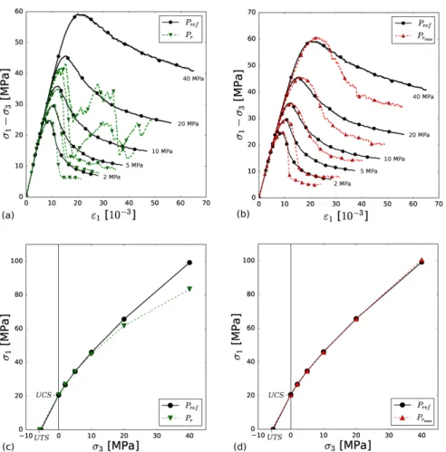
Fig. 7 Uniaxial compression test simulations performed on Pref, Prand Prmax: (a) using the same set of interparticle properties for all packings (2), (b) using adjusted sets of interparticle properties (3). The Young’s moduli E as well as the uniaxial compressive strengths U CS of the packings were estimated from these curves as illustrated on Fig. 7(b).
Table 3 Calibrated values of the bonded particle model parameters to adjust the macroscopic mechanical properties of the constructive packings Pr and Prmax.
Packing Elastic modulus Stiffnesses ratio Tensile strength Cohesion Friction angle Pi Eeq(GPa) kn/ks t (MPa) c (MPa) φ (◦)
Pr 12.6 10 16.6 16.6 12
Prmax 11.6 10 13.8 13.8 12
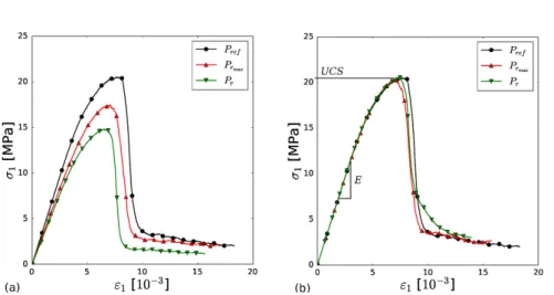
The stress-strain curves corresponding to the uniaxial compression test simu-lations are presented in Fig. 7(a). Overall, the emergent behaviors of all packings are qualitatively very similar and typical of what is expected for a brittle rock ma-terial [20]. Nonetheless, as reported in a previous study dedicated to characterize the effect of porosity on the behavior of rocks [40], the smaller SF is, the weaker the simulated medium is. Both constructive packings Prand Prmax show smaller
Young’s moduli and uniaxial compressive strengths compared to Pref. This is not
really problematic since we can easily compensate for this reduced macroscopic properties by increasing the interparticle properties accordingly as illustrated in Fig. 7(b) where the same simulations were run using the parameters given in Ta-ble 3. With such adjusted parameters, all three packings show the same emergent properties when subjected to uniaxial compression.
At this stage, it is however important to make sure that the behavior of each packing is not loading-path dependent since geological media can be subjected to various stress and strain states. Indeed, only considering a uniaxial compression test for characterizing the behavior of a DEM model, even though repeatedly done in the literature, is not sufficient to ensure that it is representative of the material to model (i.e., a rock). We thus simulate a series of triaxial compression tests under 2, 5, 10, 20 and 40 MPa confining pressures, as well as uniaxial tension tests
Fig. 8 Mechanical characterization of the generated packings: stress-strain responses of Pr
(a) and Prmax(b) subjected to triaxial compression tests performed under confining pressures σ3 equal respectively to 2, 5, 10, 20 and 40 MPa; and complete failure envelopes of Pr (c)
and Prmax (d), encompassing their triaxial compressive strengths as well as their uniaxial compressive strength (UCS), and their uniaxial tensile strength (UTS).
on all three packings to assess their mechanical behavior more systematically. The results of all these tests are summarized in Fig. 8.
Firstly, both Pr and Prmax reproduce the tensile strength of Pref as shown
by the intersection of the envelope with the horizontal axis (Fig. 8(c) and 8(d)). Secondly, while Prmax reproduces relatively well the behavior of Pref for every
confining pressures tested here, Prfails to do so (Fig. 8(a)). In fact, due to its
rel-atively lower SF , Pr tends to collapse under higher compressive stresses (20 and
40 MPa), similarly to what can be observed with high porosity rocks. Even though of potential interest in such a specific case, this result highlights a limitation of Pr
since it cannot reproduce the benchmark behavior of Pref at high confining
pres-sures. Consequently, the failure envelope of Prdeviates from the envelope of Pref
such conditions. In a lesser degree, the behavior of Prmax starts to deviate from the
reference under 40 MPa of confinement (Fig. 8(b) and 8(d)). Prmax does not
col-lapse abruptly like Prduring the simulation but it shows a compressive behavior
instead of the dilative behavior expected and predicted by Pref in the post-peak
regime. These drawbacks cannot be identified if only uniaxial compression test simulations are considered to characterize the behavior of the packings.
To sum up, both constructive packings can be used with confidence to repro-duce typical rock behaviors under low confining pressures (c.f., uniaxial tension and uniaxial compression). Under higher confining stresses, the representativeness of the packings has to be assessed through systematic mechanical testing (e.g., triaxial compressions at different confining pressures to identify the stress level at which their structural characteristics influence the simulated behavior). Clearly, we show here that packings with high SF are necessary to perform DEM simulations under high stress levels and avoid bias induced by their fabric. In the eventuality that the packings generated with the proposed algorithm are not dense enough for the considered application, it would potentially be possible to further compact them dynamically by running a dedicated DEM simulation where, for example, an expansion of the particles could be applied. This result must be kept in mind when applying the DEM to geomechanical problems involving high depths or large scale lengths (e.g., tectonics, reservoir or petroleum engineering).
3.3 Failure mechanisms
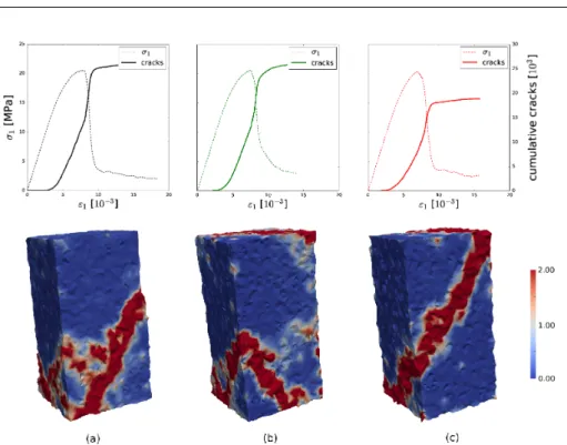
A fundamental feature of DEM models lies in their ability to explicitly describe progressive failure mechanisms at stake in geomaterials like, for instance, the initi-ation, coalescence, and propagation of cracks which lead rock materials to failure [37, 38]. Since materials’ microstructures can influence such mechanisms [18], it is essential to assess the potential of our algorithm to produce packings relevant with regards to this aspect. We thus monitor the failure mechanisms occurring during the uniaxial compression test simulations presented in the previous section and compare the outputs obtained with all three packings (Fig. 9).
As classically observed in rocks, failure develops in all three packings as a result of the progressive increase of damage (cracking) inside the material. In a BPM, cracks result from the breakage of interparticle bonds when they cannot bear any-more the load they are subjected to (uniaxial compression here). As illustrated by the rate of cracking, the kinetics of damage is qualitatively similar for all packings except that less cracks are induced in Prmax as it contains less particles, hence
less interparticle bonds likely to break. At failure (after the stress peak), strain softening is associated to a drastic increase of the cracking rate and to strain local-ization materializing inside all three packings through shear bands. These bands show slightly different morphologies in each case since each packing has its own microstructure. Nevertheless, all three bands share similar orientation with respect to the loading direction, proving that they all share the same mechanical origin. Note nonetheless that the failure pattern obtained with Pr is different from the
two others since two bands developed at both extremities of the specimen. These suggest that failure might occur as a result of preferential compaction close to the boundaries where the loading is applied as a result of the lowest SF of the packing. Actually, this is probably related to the post-peak response of Pr which
Fig. 9 Failure mechanisms obtained respectively on (a) Pref, (b) Pr and (c) Prmax when subjected to uniaxial compression tests: (top) stress-strain responses and associated cracks, and (bottom) deformation field (norm of the deviatoric strain) at the end of the test.
is slightly less brittle than for the other two packings (see the curvature of both the stress and cracks curves before the residual state is reached).
These results confirm that packings with higher SF ensure the soundness of the simulated behavior. Prmax thus appears to be the most suitable packing for
performing DE modeling of rock materials. Even though its particle size distribu-tion is slightly peculiar (Fig. 5), we have shown that, similarly to Pref, it can be
used with confidence to simulate the mechanisms at stake in rock materials.
4 Packing spheres in geological models
Geological processes create complex environments that contain sedimentary, me-chanical or diagenetic heterogeneities of various sizes. Considering the crucial im-pact of such heterogeneities on rock physical behavior, they need to be explicitly considered in numerical models aiming to simulate geological processes. Given the potential of the DEM for studying such processes (e.g., large deformations, frac-turing), the ability to discretize structurally complex objects with mechanically sound particle packings if thus of great interest.
In the following sections, we illustrate the algorithm capabilities to generate packings that honor both outer and inner boundaries of surface-based geological models [6], as well as its ability to produce adaptive particle packings in cases where structures of interest need to be finely discretized. We built the packings
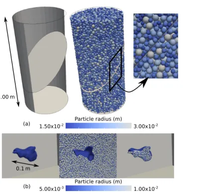
Particle radius (m) 1.50x10⁻² 3.00x10⁻² (a) Particle radius (m) 5.00x10⁻³ 1.00x10⁻² (b) 1.00m 0.1m
Fig. 10 Conformity of packings with surface boundaries: (a) a cylindrical sample containing a throughgoing fault. The packing is composed by 18,782 spheres, 9,476 spheres are in the upper part of the core (above the discontinuity) and 9306 are in the bottom part of the core (below the discontinuity). (b) an arbitrary shaped pore within an homogeneous medium. The packing contains 407,131 spheres, 637 spheres inside the pore and, 406,494 spheres outside the pore.
presented in this study from boundary representations of geological models pro-vided by the RINGMesh library [35]. For all cases, we use the option r = rmaxto
produce as dense as possible packings since they seem to be more appropriate for geomechanical studies as demonstrated in Sect 3.
4.1 Conformity to boundaries
To illustrate the capability of the algorithm to ensure spheres to be tangent to both external and internal boundaries, we consider two different models presented in Fig. 10. First, a cylindrical sample containing a throughgoing fault is discretized with spheres with sizes defined such that rmax/rmin = 2, with rmax = L/10,
L being the sample diameter in this case (Fig. 10(a)). Similarly to the external boundaries, the fault is explicitly represented by particles perfectly tangent to both sides of its surface. Considering discontinuities in DEM models is commonly done through the used of the smooth joint (SJ) approach [19, 38] which actually does not require particles to be tangent to the discontinuity surfaces. Although very useful in practice since the SJ approach can be used without any geometrical constraints on the packing used (the discontinuity surfaces are simply overlapped on the particles as illustrated in Fig. 11(a)), this feature relies on the possibility for
Fig. 11 DEM simulation of a discontinuity surface under shear with the smooth joint (SJ) approach [19, 38]: (a) using a conform packing, (b) using a conform packing. The non-conform packing does not ensure mass conservation during deformation due to a large overlap between particles.
the spheres located on both sides of the interface to go across one another under shear, hence not ensuring mass (volume) conservation when the medium deforms (Fig. 11(a)). The possibility of generating packings with spheres exactly tangent to the interface guarantees mass conservation during deformation and constitutes therefore a certain benefit with respect to this aspect as depicted in Fig. 11(b).
Of course, this capability to ensure tangency of spheres along surfaces is not restricted to plane surfaces as illustrated in Fig. 10(b) where the algorithm is used to discretize a homogeneous medium containing an irregular cavity (pore). For illustration purpose, both the matrix and the pore have been filled with particles. All particles, located either in the matrix or in the pore, honor a tangential contact with the pore boundary, even though the latter present a very tortuous surface.
4.2 Spatial refinements
Running DEM simulations on large scale models can be computationally expen-sive. This is particularly true if these models present a high level of details due to the presence of structures (e.g., discontinuities, cavities); and if these structures present a relatively small characteristic length compared to the model size. Indeed, it is important to adapt the resolution of the packing to the characteristic length of the structure of interest to ensure a good approximation of the phenomenon at stake. For instance, when modeling geomaterials with the DEM, a representa-tive elementary volume of length L must be discretized with particles of average radius equal to at least L/10 [5]. Under such a condition, geological objects that
classically contains many features with different length scales would require a sub-sequent amount of particles to be modeled with the DEM. Of course, the DEM can be parallelized quite easily to enhance its efficiency with regards to this aspect [32, 45]. Nonetheless, it is worth considering the possibility to locally adapt parti-cle resolution according to the spatial organization of structures, specially if large scale geological objects are to be modeled. This is commonly done in the Finite Element Method simulations in order to minimize the computational cost in areas where a high accuracy is not needed so as to reduce the global simulation time. Spatial particle size variations have been used in DEM simulations with the same purpose [28] but the radius variation seemed to be discontinuous and the filling method defined manually.
The proposed algorithm is able to produce adaptive packings by locally varying the targeted radius r using a progressive and controlled manner. The smallest characteristic length L of the model is given as an input to define the particle size range [rmin, rmax] needed to capture the structures of interest (e.g., rmax=
L/10). Then, the structures that need to be captured with the highest resolution are identified within the geological model and a distance range d is setup from these discontinuities. d is combined with two additional inputs that weight the particle radii. The user defines (1) the maximum weighting factor wmaxto apply
on the initial particle size range and (2) the number of sphere N tspheres that
will be used to accommodate the transition between both the minimum and the maximum particle size ranges. Finally, the weighting factor w to apply is evaluated (Equation 8) considering d and the two thresholds dmin= N tspheres× rmaxand
dmax= wmax× dmin:
w = 1.0 if d < dmin 1.0 + (wmax− 1.0) ×dd−dmin
max−dmin if dmin< d < dmax
wmax if d > dmax.
(8)
The procedure ensures a progressive transition between zones of high resolu-tion close to the identified structures and zones of low resoluresolu-tion elsewhere. For this application, the convergence index CI (Equation 3) needs to be adjusted by multiplying rmin with wmax in Equation 9 to avoid an underestimation of the
volume sampled: CI = na4π 3 (wmax× rmin)3 Vref . (9)
To illustrate the proposed approach, we consider the model presented in Fig. 12. A packing generated without any spatial refinement is presented for reference (Fig. 12(b)). Two packings are generated with the same weighting factors wmax=
2.0 but different N tspheres. The packings built respectively with N tspheres = 10
(Fig. 12(c)) and with N tspheres = 20 (Fig. 12(d)) contain respectively 71% and
46% less particles than the reference packing while keeping the same discretiza-tion around the fracture. To go further a sensitivity analysis could be performed to actually assess whether all these packings have similar mechanical behaviors. Nev-ertheless, the proposed approach shows a great potential for reducing the computa-tional effort needed for DEM simulations and opens the path toward the modeling of large scale geological models with the DEM.
(a) (b) (c) (d) Particle radius (m)
9.0x10⁻³ 3.6x10⁻²
1.0 m
Fig. 12 Spatial refinement capacity of the algorithm: (a) model to be filled with particles (parallelepiped of dimensions 1.0 × 2.0 × 0.2 m containing a fracture of dimensions 0.4 × 0.2 m dipping at 45◦), (b) homogeneous packing containing 14,989 spheres with rs∈ [0.009, 0.018],
(c) adaptive packings defined such as wmax= 2.0 and N tspheres= 10, containing 4,284 spheres
and, (d) adaptive packings defined such as wmax= 2.0 and N tspheres= 20, containing 8,061
spheres.
4.3 Case of a geological model
We illustrate here the ability of the algorithm to generate adaptive sphere packings for DE modeling of realistic geological settings by considering a model of dimen-sions 17 × 10 × 5 km that integrates two stratigraphic horizons and two faults. One fault crosses entirely the model and the other stops within its bulk. The model and the packing are presented in Fig. 13.
We set rmax to be equal to one tenth of the minimal characteristic length
L of the model which, in this case, corresponds to the distance between the two horizons (≈ 1000 m). rmaxis thus equal to 100 m. We decided to fix the particle size
ratio such as rmax/rmin= 2, meaning that rmin= 50 m. These values define the
packing resolution around the faults. To illustrate the refinement capacity of the algorithm, we vary the resolution while getting away from the faults using wmax=
3 and N tspheres= 20. The algorithm efficiently deals with all the constraints, i.e.,
particle size variation in between faults and tangency of spheres with all boundaries (Fig.13).
5 Conclusion
The ability to pack particles in geological objects opens great potential for their mechanical modeling with the DEM. In such context, we propose an algorithm inspired by the space filling Apollony fractal that is able to fill geological models such that:
- the produced packings are mechanically sound when utilized in DEM simula-tions;
(d) (c) (b) (a) 100 m Particle radius (m) 5.0x101 3.0x10²
Fig. 13 Sphere packing generated in a 3D geological model considering both surface confor-mity and spatial refinement: (a) structural model with two horizons and two faults, (b) and (c) inside views of the packing (the particles are smaller close to the faults and tangent to all boundaries), (d) global view of the packing. The resulting packing contains 97,303 spheres with radii rs∈ [50, 300] m.
- the produced packings are conform with the surface boundaries of the models, either external or internal (fractures, cavities);
- spatial variations of the packing resolution can be achieved around structures of interest.
The proposed algorithm is an offspring of the Protosphere algorithm that en-ables to restrict the particle sizes to a predefined range defined by the user, e.g., as a function of the characteristic length of the model. Two options can be used to control the particle size distribution of the produced packings. One maximizes the particle sizes during the generation process while the other distributes the particle sizes more homogeneously over the predefined size range. Both options were assessed through a systematic characterization of both the geometric and mechanical properties of one of their productions. Both packings present isotropic structures. The size-maximized packing is denser than the size-distributed one. Mechanical testing of both packings revealed that the densest packing is mechan-ically the soundest since it can reproduce rock-like material behaviors under dif-ferent loading paths (e.g., uniaxial and triaxial compressions, uniaxial tension). The size-distributed packing shows undesirable behaviors when subjected to high compressive stresses: due to its higher porosity, its structure collapses on itself under load. Such a behavior might be problematic in large scale DEM simulations were discrete elements are used as a mean to represent large volumes of materials and not actual grains.
Through dedicated examples, we have shown the capabilities of the algorithm to fill in 3D models representing geological objects of different shapes and contain-ing embedded discontinuities. We have illustrated its ability to ensure the tangency of spheres with both external and internal boundaries. We also have highlighted its capability to generate adaptive packings which could be relevant for large scale DE modeling where emphasis has to be put on mechanisms taking place in identified localized areas (e.g., around faults).
The filling capabilities of the proposed algorithm are promising for performing DE modeling of geological systems that we are currently considering as a direct continuation of this work. Of course, there is still room for improvement. The ef-ficiency of the algorithm could be enhanced either by parallelizing the generation procedure or by using the acceleration techniques proposed in [44] for the Proto-sphere algorithm. Another improvement would consist in generating packings with non-spherical particles to integrate an explicit description of anisotropic structures in DEM simulations. This may be useful for modeling particular rock formations that present strong anisotropies caused by the shape of their constitutive particles like, for instance, shale or clay rocks.
Acknowledgements This work was performed in the framework of the RING project at Universit´e de Lorraine (http://ring.georessources.univ-lorraine.fr/). We would like to thank the industrial and academic sponsors of the RING-GOCAD Consortium managed by ASGA for their support. We also want to acknowledge INRIA for the Geogram library and Emerson for providing the Skua-Gocad software.
Funding: This study was funded by the RING-GOCAD Consortium managed by ASGA. Conflict of Interest: The authors declare that they have no conflict of interest.
References
1. Bagi, K.: An algorithm to generate random dense arrangements for discrete element sim-ulations of granular assemblies. Granular Matter 7(1), 31–43 (2005)
2. Benabbou, A., Borouchaki, H., Laug, P., Lu, J.: Geometrical modeling of granular struc-tures in two and three dimensions. application to nanostrucstruc-tures. International Journal for Numerical Methods in Engineering 80, 425–454 (2009)
3. Borkovec, M., De Paris, W., Peikert, R.: The fractal dimension of the apollonian sphere packing. Fractals 2(4), 521–526 (1994)
4. Boutt, D., McPherson, B.: The Role of Particle Packing in Modeling Rock Mechanical Behavior using Discrete Elements, pp. 86–92. DOI 10.1061/40647(259)16
5. Calvetti, F., Combe, G., Lanier, J.: Experimental micromechanical analysis of a 2d granu-lar material: relation between structure evolution and loading path. Mechanics of Cohesive-frictional Materials 2(2), 121–163 (1997)
6. Caumon, G., Collon-Drouaillet, P., Le Carlier de Veslud, C., Viseur, S., Sausse, J.: Surface-based 3d modeling of geological structures. Mathematical Geosciences 41(8), 927–945 (2009)
7. Chang, C.S., Misra, A.: Packing structure and mechanical properties of granulates. Journal of Engineering Mechanics 116(5), 1077–1093 (1990)
8. Ciantia, M., Boschi, K., Shire, T., Emam, S.: Numerical techniques for fast generation of large discrete-element models. Engineering and Computational Mechanics pp. 1–34 (2018). DOI 10.1680/jencm.18.00025
9. Cui, L., O’Sullivan, C.: Analysis of a triangulation based approach for specimen generation for discrete element simulations. Granular Matter 5(3), 135–145 (2003)
10. Cundall, P.A., Strack, O.D.L.: A discrete numerical model for granular assem-blies. G´eotechnique 29(1), 47–65 (1979). DOI 10.1680/geot.1979.29.1.47. URL https://doi.org/10.1680/geot.1979.29.1.47
11. Donz´e, F.V., Richefeu, V., Magnier, S.A.: Advances in discrete element method applied to soil, rock and concrete mechanics. Electronic Journal of Geotechnical Engineering 8 (2008)
12. Govender, N., Wilke, D.N., Kok, S.: Collision detection of convex polyhedra on the nvidia gpu architecture for the discrete element method. Applied Mathematics and Computation 267, 810 – 829 (2015)
13. Gray, G.G., Morgan, J.K., Sanz, P.F.: Overview of continuum and particle dynamics meth-ods for mechanical modeling of contractional geologic structures. Journal of Structural Geology 59, 19–36 (2014)
14. Han, K., Feng, Y.T., Owen, D.R.J.: Filling domains with disks: an advancing front ap-proach. International Journal for Numerical Methods in Engineering 56, 699–713 (2005) 15. Hardy, S.: Structural evolution of calderas: Insights from two-dimensional discrete element
simulations. Geology 36(12), 927–930 (2008)
16. Herrmann, H., Baram, R.M., Wackenhut, M.: Searching for the perfect packing. Physica A: Statistical Mechanics and its Applications 330(1), 77 – 82 (2003)
17. Hitti, K., Bernacki, M.: Optimized dropping and rolling (odr) method for packing of poly-disperse spheres. Applied Mathematical Modelling 37(8), 5715 – 5722 (2013)
18. Hoagland, R.G., Hahn, G.T., Rosenfield, A.R.: Influence of microstructure on fracture propagation in rock. Rock Mechanics & Rock Engineering 5(2), 77–106 (1973)
19. Ivars, D.M., Pierce, M.E., Darcel, C., Reyes-Montes, J., Potyondy, D.O., Young, R.P., Cundall, P.A.: The synthetic rock mass approach for jointed rock mass modelling. Inter-national Journal of Rock Mechanics and Mining Sciences 48(2), 219 – 244 (2011) 20. Jaeger, J., Cook, N., Zimmerman, R.: Fundamentals of rock mechanics, 4th edition.
Wiley-Blackwell (2007)
21. Jerier, J.F., Harthong, B., Richefeu, V., Chareyre, B., Imbault, D., Donze, F.V., Doremus, P.: Study of cold powder compaction by using the discrete element method. Powder Technology 208(2), 537 – 541 (2011)
22. Jerier, J.F., Imbault, D., Donze, F.V., Doremus, P.: A geometric algorithm based on tetrahedral meshes to generate a dense polydisperse sphere packing. Granular Matter 11(1), 43–52 (2009)
23. Jerier, J.F., Richefeu, V., Imbault, D., Donz´e, F.V.: Packing spherical discrete elements for large scale simulations. Computer Methods in Applied Mechanics and Engineering 199(25), 1668 – 1676 (2010)
24. Jiao, L., Tapponnier, P., Costa, F., Donz´e, F.V., Scholt`es, L., Taisne, B., Wei, S.: Necking and fracking may explain stationary seismicity and full degassing in volcanic silicic spine extrusion. Earth and Planetary Science Letters 503, 47 – 57 (2018)
25. Kansal, A., Torquato, S., Stillinger, F.: Computer generation of dense polydisperse sphere packings. The Journal of Chemical Physics 117(18), 8212–8218 (2002)
26. Kirkpatrick, S., Gelatt, C.D., Vecchi, M.P.: Optimization by simulated annealing. science 220(4598), 671–680 (1983)
27. Lozano, E., Roehl, D., Celes, W., Gattass, M.: An efficient algorithm to generate random sphere packs in arbitrary domains. Computers and Mathematics with Applications 71, 1586–1601 (2016)
28. McDowell, G., Falagush, O., Yu, H.S.: A particle refinement method for simulating dem of cone penetration testing in granular materials. G´eotechnique Letters 2(3), 141–147 (2012) 29. Moosavi, S., Scholt`es, L., Giot, R.: Influence of stress induced microcracks on the tensile
fracture behavior of rocks. Computers and Geotechnics 104, 81–95 (2018)
30. Morfa, C., L.A., C., Muniz de Farias, M., Perez Morales, I.P.P., Rosello Valera, R., O˜nate Iba˜nez de Navarra, E.: Systemic characterization and evaluation of particle packings as initial sets for discrete element simulations. Computational Particle Mechanics 5(3), 319– 334 (2018)
31. Morgan, J.K., Boettcher, M.S.: Numerical simulations of granular shear zones using the distinct element method: 1. shear zone kinematics and the micromechanics of localization. Journal of Geophysical Research: Solid Earth 104(B2), 2703–2719 (1999)
32. Nishiura, D., Matsuo, M.Y., Sakaguchi, H.: ppohdem: computational performance for open source code of the discrete element method. Computer Physics Communications 185(5), 1486–1495 (2014)
33. O’Sullivan, C.: Particulate discrete element modelling: a geomechanics perspective. CRC Press (2011)
34. Papachristos, E., Scholt`es, L., Donz´e, F., Chareyre, B.: Intensity and volumetric character-izations of hydraulically driven fractures by hydro-mechanical simulations. International Journal of Rock Mechanics and Mining Sciences 93, 163–178 (2017)
35. Pellerin, J., Botella, A., Bonneau, F., Mazuyer, A., Chauvin, B., L´evy, B., Caumon, G.: Ringmesh: A programming library for developing mesh-based geomodeling applications. Computers & Geosciences 104, 93–100 (2017)
36. Potyondy, D.: The bonded-particle model as a tool for rock mechanics research and ap-plication: Current trends and future directions. Geosystem Engineering 17 (2014). DOI 10.1080/12269328.2014.998346
37. Potyondy, D., Cundall, P.: A bonded-particle model for rock. International Journal of Rock Mechanics and Mining Sciences 41(8), 1329 – 1364 (2004)
38. Scholt`es, L., Donz´e, F.V.: Modelling progressive failure in fractured rock masses using a 3d discrete element method. International Journal of Rock Mechanics and Mining Sciences 52, 18–30 (2012)
39. Scholt`es, L., Donz´e, F.V.: A dem model for soft and hard rocks: role of grain interlocking on strength. Journal of the Mechanics and Physics of Solids 61(2), 352–369 (2013) 40. Sch¨opfer, M., Abe, S., Childs, C., Walsh, J.: The impact of porosity and crack density
on the elasticity, strength and friction of cohesive granular materials: Insights from dem modelling. International Journal of Rock Mechanics and Mining Sciences 46(2), 250–261 (2009)
41. Siiri¨a, S., Yliruusi, J.: Particle packing simulations based on newtonian mechanics. Powder Technology 174(3), 82 – 92 (2007)
42. Smilauer, V., Catalano, E., Chareyre, B., Dorofeenko, S., Duriez, J., Dyck, N., Elias, J., Er, B., Eulitz, A., Gladky, A., Guo, N., Jakob, C., Kneib, F., Kozicki, J., Marzougui, D., Maurin, R., Modenese, C., Scholtes, L., Sibille, L., Stransky, J., Sweijen, T., Thoeni, K., Yuan, C.: Yade Documentation 2nd ed. Zenodo (2015). DOI 10.5281/zenodo.34073. URL https://doi.org/10.5281/zenodo.34073
43. Stroeven, P., Stroeven, M.: Assessment of packing characteristics by computer simulation. Cement and Concrete Research 29(8), 1201 – 1206 (1999)
44. Teuber, J., Weller, R., Zachmann, G., Guthe, S.: Fast sphere packings with adaptive grids on the gpu. GI AR/VRWorkshop (W¨urzburg, Germany, vol. 4 (2013)
45. Tian, Y., Zhang, S., Lin, P., Yang, Q., Yang, G., Yang, L.: Implementing discrete element method for large-scale simulation of particles on multiple gpus. Computers & Chemical Engineering 104, 231–240 (2017)
46. Valera, R.R., Morales, I.P., Vanmaercke, S., Morfa, C.R., Cort´es, L.A., Casa˜nas, H.D.G.: Modified algorithm for generating high volume fraction sphere packings. Computational Particle Mechanics 2(2), 161–172 (2015)
47. Wang, X., Morgan, J.K.: Controls on fore-arc deformation and stress switching after the great 2011 tohoku-oki earthquake from discrete numerical simulations. Journal of Geo-physical Research: Solid Earth 124(8), 9265–9279 (2019). DOI 10.1029/2019JB017420. URL https://agupubs.onlinelibrary.wiley.com/doi/abs/10.1029/2019JB017420
48. Weisstein, E.W., Problem, C.: From mathworld—a wolfram web resource http://mathworld. wolfram. com. MeanCurvature. html (2005)
49. Weller, R., Zachmann, G.: Protosphere: A gpu-assisted prototype guided sphere packing algorithm for arbitrary objects. In: ACM SIGGRAPH ASIA 2010 Sketches, SA ’10, pp. 8:1–8:2 (2010)
![Fig. 4 Monitoring of the filling process: (a) r ∈ [r min , r max ] and (b) r = r max](https://thumb-eu.123doks.com/thumbv2/123doknet/14802027.606673/8.892.114.616.120.336/fig-monitoring-filling-process-r-min-max-max.webp)
![Table 1 Macroscopic properties of the packings generated respectively such as r ∈ [r min , r max ] and r = r max (Fig](https://thumb-eu.123doks.com/thumbv2/123doknet/14802027.606673/9.892.106.628.177.251/table-macroscopic-properties-packings-generated-respectively-min-fig.webp)
![Fig. 6 Packings obtained respectively using (a) the compression method implemented in YADE DEM (P ref ), (b) the proposed constructive method with r ∈ [r min , r max ] (P r ) and, (c) the proposed constructive method with r = r max (P r max ).](https://thumb-eu.123doks.com/thumbv2/123doknet/14802027.606673/11.892.109.622.121.475/packings-obtained-respectively-compression-implemented-proposed-constructive-constructive.webp)
![Fig. 11 DEM simulation of a discontinuity surface under shear with the smooth joint (SJ) approach [19, 38]: (a) using a conform packing, (b) using a conform packing](https://thumb-eu.123doks.com/thumbv2/123doknet/14802027.606673/17.892.110.590.110.458/simulation-discontinuity-surface-approach-conform-packing-conform-packing.webp)
