Publisher’s version / Version de l'éditeur:
Canadian Acoustics, 32, September 3, pp. 166-167, 2004-09-01
READ THESE TERMS AND CONDITIONS CAREFULLY BEFORE USING THIS WEBSITE.
https://nrc-publications.canada.ca/eng/copyright
Vous avez des questions? Nous pouvons vous aider. Pour communiquer directement avec un auteur, consultez la première page de la revue dans laquelle son article a été publié afin de trouver ses coordonnées. Si vous n’arrivez pas à les repérer, communiquez avec nous à PublicationsArchive-ArchivesPublications@nrc-cnrc.gc.ca.
Questions? Contact the NRC Publications Archive team at
PublicationsArchive-ArchivesPublications@nrc-cnrc.gc.ca. If you wish to email the authors directly, please see the first page of the publication for their contact information.
NRC Publications Archive
Archives des publications du CNRC
This publication could be one of several versions: author’s original, accepted manuscript or the publisher’s version. / La version de cette publication peut être l’une des suivantes : la version prépublication de l’auteur, la version acceptée du manuscrit ou la version de l’éditeur.
Access and use of this website and the material on it are subject to the Terms and Conditions set forth at
On transmission of structure borne power from wood studs to gypsum
board mounted on resilient metal channels - Part 2: Some
simplifications for modelling
Mayr, A. R.; Nightingale, T. R. T.
https://publications-cnrc.canada.ca/fra/droits
L’accès à ce site Web et l’utilisation de son contenu sont assujettis aux conditions présentées dans le site LISEZ CES CONDITIONS ATTENTIVEMENT AVANT D’UTILISER CE SITE WEB.
NRC Publications Record / Notice d'Archives des publications de CNRC:
https://nrc-publications.canada.ca/eng/view/object/?id=837b11dd-1bdf-43c1-8937-0a91408ea2df
https://publications-cnrc.canada.ca/fra/voir/objet/?id=837b11dd-1bdf-43c1-8937-0a91408ea2df
On transmission of structure borne power from wood
studs to gypsum board mounted on resilient metal
channels – Part 2: Some simplifications for modelling
Mayr, A.; Nightingale, T.R.T.
NRCC-45338
A version of this document is published in / Une version de ce document se trouve dans :
Canadian Acoustics/Acoustique canadienne, v. 32, no. 3, Sept. 2004, pp. 166-167
ON TRANSMISSION OF STRUCTURE BORNE POWER FROM WOOD STUDS TO GYPSUM BOARD MOUNTED ON RESILIENT METAL CHANNELS – PART 2: SOME SIMPLIFICATIONS FOR MODELLING
Andreas Mayr† and T.R.T. Nightingale§
†
Department of Bauphysik, University of Applied Science Stuttgart, Schellingstrasse 24, D-70174 Stuttgart, Germany
§
Institute for Research in Construction, National Research Council, Ottawa, Ontario, Canada K1A OR6 1. INTRODUCTION
This is the second of two papers that consider the effect of resilient metal channels (RCs) on structure borne transmission from wood studs to gypsum board. Readers are referred to the first paper [1] for wall details, definitions, and measurement procedures. This paper examines several simplifications that might be used when creating a model for structure borne transmission from a wood stud to gypsum board that is mounted on RCs. Possible simplifications include assuming transmission is reasonably independent of the location of the RCs, but is dependent on the number, and that the total power transmission is simply the sum of transmission through individual RCs. The paper concludes with the reduction in radiated sound power velocity that might be expected if direct attached gypsum board is mounted on RCs.
2. EFFECT OF CHANNEL LOCATION
To estimate the variation in structure borne transmission due to a change in the location of the RC, a single RC was installed at each of the seven locations A-G shown in the insert to Figure 1 and the coupling loss factor (CLF) measured. Resilient pads supported the gypsum board at the bottom. The confidence intervals indicate that above about 400 Hz CLF does not change much with RC location. However, below 400 Hz the large confidence intervals indicate a significant variation in CLF with channel location.
Figure 1: Mean CLF for a single RC installed at positions A through G, when the stud is excited by a single point force at D.
To gain some insight into why the CLF below 400 Hz is sensitive to RC location, Figure 2 shows the RMS velocity of the stud for 125 and 200 Hz when excited at position D. The figure shows the stud can only support low order modes in these frequencies and that the RMS velocity varies significantly with location. The horizontal lines indicate the location where the resilient channels would be attached and that some RCs will be located near antinodes while others will be located near nodes. More power will be transmitted by an RC located at an antinode than the same RC located at a node despite constant stud energy. This means statistical approaches (like SEA) cannot accurately predict the power flow through individual RCs where there are few modes because estimates of the mean energy in the stud might not
be highly correlated with the velocity of the stud at the RC. With several resilient channels spaced a significant distance apart and considerably more modes in the frequency band of interest, statistical approaches will have greatly improved accuracy, because the mean stud energy will be highly correlated with the mean of the stud velocities at the RCs. Finite Element or Modal Methods could have given more accurate estimates of low frequency transmission, if the boundary conditions of the studs and gypsum board are known. But, in reality the boundary conditions are not well known and will vary from one stud to the next because of workmanship and variations in material properties.
Figure 2: Stud vibration response at 125 and 200 Hz expressed as RMS velocity when excited by a point force applied at Position D.
3. APPROXIMATING TOTAL POWER FLOW
It is often assumed that the total power flow between systems coupled by a series of well-defined point contacts can be approximated by the sum of the power flow at each point. This implies that the motion of each fastener is incoherent such that each fastener appears to be an incoherent source and the powers simply add. This will not be the case when the spacing between the fasteners is such that the points are coherent which as some have suggested occurs when the spacing is less than half a wavelength.
To verify this assumption, the individual CLF’s obtained from the work described in Figure 1 were used to estimate the total CLF, and hence total power flow, that would be exist for an arbitrary number and distribution of RCs. If the points act incoherently then there will be good agreement between measured and summed CLF’s. Figure 3 shows results for the case where there are 7 RCs (A through G) and 3 RCs (A, D, and G). There is good agreement between the measured total CLF with 3 RCs and the estimate obtained from the sum of CLF’s. The agreement for 7 RCs is not as good. The sum of individual CLF’s slightly overestimates the total CLF. With 7 RCs, the spacing between the RCs is about 400 mm and is small compared to the bending wavelength in the studs at low frequencies. Thus, the motion of the fastening points will not be fully incoherent and the total power flow will be less than that predicted from a simple sum. The cause for the 1-2 dB
80 85 90 95 100 105 110 115 120 50 100 200 400 800 1600 3150 Frequency, Hz C LF, [dB r e 1 0 -1 2]
Mean CLF for single channel located at position A through G
A B C D E F G
Mean CLF for a single RC and 95% confidence interval
85 90 95 100 105 110 115 120 125 50 100 200 400 800 1600 3150 Frequency, Hz CLF, [dB r e 1 0 -1 2] Sum of the 7 individual CLF's Measured 3 RC's (A,D,G) Measured 7 RC's (A,B,C,D,E,F,G) Sum of the 3 individual CLF's Direct attached with 7 screws (A,B,C,D,E,F,G) With RC's -20 -15 -10 -5 0 5 10 50 100 200 400 800 1600 3150 Frequency, Hz Cha nge i n Ra di a te d S ound P o w e r, dB
Structurally excited single leaf wall shown in Figure 1 Structure borne flanking path
(IRC flanking facility)
Change in Radiated Sound Power due to adding RC's
overestimation for frequencies above 315 Hz is not known. The effectiveness of RCs to attenuate structure borne transmission can be seen from Figure 3 by the significantly greater CLF for directly attached gypsum board.
Figure 3: Comparison of measured CLF’s and those computed by summing the CLF’s for the individual RCs.
4. RADIATION EFFICIENCY
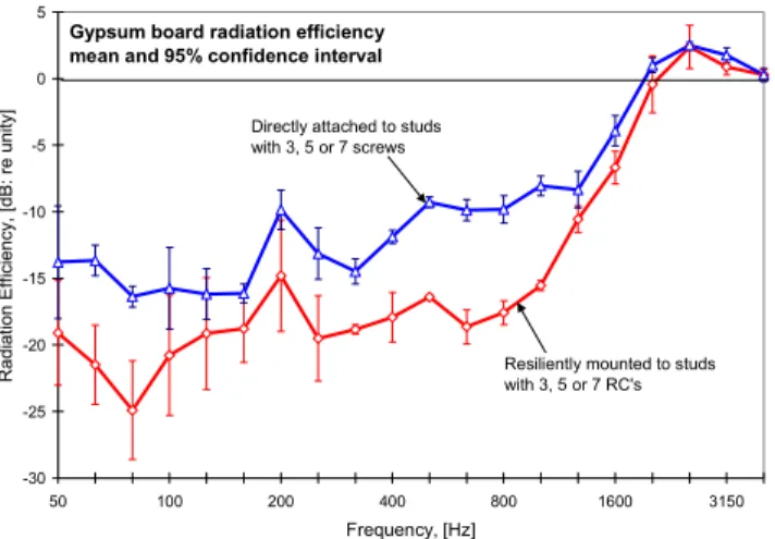
It is possible that the radiation efficiency of gypsum board will be different when directly attached to the studs and when mounted on RCs. To evaluate this, the radiation efficiency [2] of the gypsum board for resonant motion was measured when a single stud was excited at position D by a point force. The gypsum board radiation efficiency did not have a systematic dependence on the number of fasteners when directly attached to the studs or when mounted on RCs. Figure 4 shows the means for 3, 5 and 7 fasteners or RCs. The 95% confidence interval can be used to gauge the range of values. Below about 1250 Hz the radiation efficiency is between 5 and 10 dB lower when the gypsum board is mounted on RCs.
Figure 4: Estimates of radiation efficiency for gypsum board that is directly attached and mounted on RCs.
This can be explained by recognising that the radiation efficiency of 16mm gypsum board below the critical frequency (~2500 Hz) is strongly affected by the aspect ratio. Because the studs are effectively line connected to the gypsum board below about 1250 Hz due to ill-defined contact points, the gypsum board is effectively divided into a series of high aspect ratio panels each
0.4x2.4m. However, when the same panel is resiliently mounted it acts like a single low aspect ratio 1.2x2.4m sheet.
5. SUPPRESSION OF RADIATED POWER
The ability of RCs to attenuate the sound power radiated by gypsum board when one or more studs are structurally excited is the combined effect of the change in velocity level difference, VLD (between stud and gypsum board) and the change in radiation efficiency. A rough estimate of VLD change can be obtained from Figure 3; by taking the difference in the CLF’s for direct attached gypsum board and that when there are seven RCs. The change in radiation efficiency is given by the difference in the curves of Figure 4. The combination of these two differences is the change in radiated sound power for a structurally excited single leaf wall as shown in Figure 5. Above about 400 Hz, these results are in reasonable agreement with those obtained for a flanking path involving a wall that was excited by the studs. Below this frequency the general trends are the same.
Figure 5: Change in radiated sound power when direct attached gypsum board (seven screws) is mounted on five resilient channels.
6. DISCUSSION AND CONCLUSIONS
This paper showed that RCs attenuate both structure borne transmission and acoustic radiation. The result is a reduction in the radiated sound power of about 10-15 dB for frequencies greater than 100 Hz for structural excitation. This estimate was similar to that for a structure borne flanking path involving a similar wall.
Parts 1 and 2 showed that above 400 Hz power transmission is almost entirely determined by stud translation (except at very high frequencies), is proportional to the number of RCs, and is independent of number and location of fasteners between gypsum board and RCs. These properties suggest in this frequency range it might be possible to use the mobility approach if RCs can be approximated by a series of idealised springs located at points of intersection between stud and RCs. The dynamic stiffness of each spring would be equal to that of the RC at a stud. Because of the simplicity of this approach it is suggested for future work. Below 400 Hz there are few modes and RC location becomes an important factor so a mobility approach would have significant errors.
7. REFERENCES
1 T.R.T. Nightingale, Andreas Mayr, (2004), “Part 1: Force and moment transmission”, Canadian Acoustics, Vol. 32(3)
2 L. Cremer, M. Heckl, “Structure borne sound”, Springer Verlag, New York 1988. -30 -25 -20 -15 -10 -5 0 5 50 100 200 400 800 1600 3150 Frequency, [Hz] Radi ati on Effi c ienc y , [dB: r e uni ty ]
Directly attached to studs with 3, 5 or 7 screws
Gypsum board radiation efficiency mean and 95% confidence interval
Resiliently mounted to studs with 3, 5 or 7 RC's