Publisher’s version / Version de l'éditeur:
MRS Advances, 2018-11-13
READ THESE TERMS AND CONDITIONS CAREFULLY BEFORE USING THIS WEBSITE.
https://nrc-publications.canada.ca/eng/copyright
Vous avez des questions? Nous pouvons vous aider. Pour communiquer directement avec un auteur, consultez la
première page de la revue dans laquelle son article a été publié afin de trouver ses coordonnées. Si vous n’arrivez pas à les repérer, communiquez avec nous à PublicationsArchive-ArchivesPublications@nrc-cnrc.gc.ca.
Questions? Contact the NRC Publications Archive team at
PublicationsArchive-ArchivesPublications@nrc-cnrc.gc.ca. If you wish to email the authors directly, please see the first page of the publication for their contact information.
NRC Publications Archive
Archives des publications du CNRC
This publication could be one of several versions: author’s original, accepted manuscript or the publisher’s version. / La version de cette publication peut être l’une des suivantes : la version prépublication de l’auteur, la version acceptée du manuscrit ou la version de l’éditeur.
For the publisher’s version, please access the DOI link below./ Pour consulter la version de l’éditeur, utilisez le lien DOI ci-dessous.
https://doi.org/10.1557/adv.2018.614
Access and use of this website and the material on it are subject to the Terms and Conditions set forth at
Effect of hardening heat treatment on the mechanical properties of a
17-4PH stainless steel foam
Gauthier, Maxime; Katz, Aurélien; Maison, Antoine; Cojocaru, Cristian V.;
Bernier, Fabrice
https://publications-cnrc.canada.ca/fra/droits
L’accès à ce site Web et l’utilisation de son contenu sont assujettis aux conditions présentées dans le site LISEZ CES CONDITIONS ATTENTIVEMENT AVANT D’UTILISER CE SITE WEB.
NRC Publications Record / Notice d'Archives des publications de CNRC:
https://nrc-publications.canada.ca/eng/view/object/?id=7bb15398-ec12-4de7-b54a-cdd990004d5f https://publications-cnrc.canada.ca/fra/voir/objet/?id=7bb15398-ec12-4de7-b54a-cdd990004d5fEffect of a precipitation hardening treatment on the
properties of 17-4PH stainless steel foams
Maxime Gauthier1*, Aurélien Katz2, Antoine Maison2, Cristian V. Cojocaru1and Fabrice Bernier1
1National Research Council Canada, 75 de Mortagne Blvd, Boucherville, QC, Canada, J4B 6Y4
2École Supérieure d’Ingénieurs en Matériaux (ESIREM), 9 Avenue Alain Savary, 21000 Dijon, France
*Corresponding Author: Maxime.Gauthier@cnrc-nrc.gc.ca/ (450) 641-5063
Abstract
This paper presents the results of a study on the impact of a precipitation hardening treatment on the mechanical properties of 17-4PH stainless steel open-cell foams produced using a powder-metallurgy-based process patented by the National Research Council Canada (NRC). Pre-alloyed powder was used to manufacture stainless steel (SS) foams with either medium or high porosity by changing the nature of the organic binder used to process the porous materials. Some of these were kept in the as-sintered state, while others were submitted to the H900 precipitation hardening treatment frequently prescribed for 17-4PH stainless steels.
Metallurgical and physical characterization was carried out on the resulting materials, along with mechanical testing at the micro (indentation testing) and macro (compressive testing) scales. It was found that the Medium-Porosity Foams (MPF) and High-Porosity Foams (HPF) had very different morphologies, the HPFs having a delicate porous structure featuring thin sintered walls with many openings (a.k.a. windows) between the main cells, while the MPFs exhibited much thicker walls with few windows connecting the larger pores. As expected from these foam morphologies, the mechanical properties of MPFs were much higher than those of the more porous and delicate HPF materials. For both foam types, the average mechanical properties were improved by the H900 treatment. A comparison with compressive properties of 17-4PH foams taken from the literature resulted in reasonable agreement. However, the large scatter observed on the average compressive properties of the NRC foams and the slightly
different structure/composition of the literature materials mean that any comparison between these porous alloys must be interpreted with caution.
INTRODUCTION
Metal foams are a family of advanced engineered materials getting an increasing amount of attention from both the scientific and industrial communities. This is due to the remarkable range of properties of these materials, which include low densities, high specific mechanical properties (strength, stiffness), high impact energy absorption, high thermal stability and heat conductivity, electrical conductivity, and good sound absorption characteristics. Such materials come in two general categories based on their cell structure: closed or open-cell foams. Closed-cell metal foams are generally chosen for lightweight structures (i.e. load-bearing applications) while the permeability of open-cell metal foams makes them ideal candidates for applications which feature an exchange between the solid foam and a fluid (electrodes, filters, heat exchangers, catalyst supports, etc).
A number of different processes have been devised to produce metal foams. These are summarized in several books and journal reviews [1-4].While the majority of the development effort has been focused on closed-cell aluminum foams [5], foams made of other metals and alloys might be better suited for applications where aluminium is not adequate from the mechanical, chemical and/or thermal point of view. In this respect, stainless steel foams may represent an interesting alternative as stainless steels are resistant to oxidation/corrosion in a variety of conditions of engineering interest and can present a range of mechanical properties depending on the grade and microstructure of the chosen stainless steel. Of the common stainless steel grades, the precipitation hardening ones like 17-4PH are particularly attractive as their mechanical properties can easily be modified through heat treatments. Some 17-4PH stainless steel foams have been processed in the past and were evaluated for different applications [6-8], but not much work was carried as compared to the numerous studies on aluminium foams, e.g. [9].
The objectives of this work are thus to 1) manufacture open-cell 17-4PH foams using a process developed by NRC and 2) evaluate the impact of the H900 heat treatment on the properties of medium- and high-porosity 17-4PH foams at the micro and macro scales.
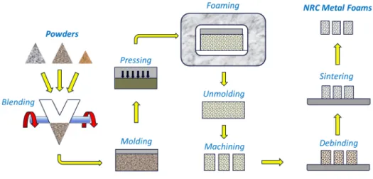
The metal foam production method patented by NRC scientists [10] can be used to produce open-cell foams made of different metals, alloys or ceramic materials (Figure 1). Briefly, a dry powder blend made of metal, organic (thermoplastic or thermoset polymer) binder and chemical foaming agent powders is moulded, lightly compacted by hand and submitted to a three-step heat treatment to 1) foam, 2) debind and 3) sinter the metal particles. During the foaming step, a suspension of metal particles in a molten binder matrix is created. Once the binder is in the molten state, the chemical foaming agent decomposes and generates a gas phase which expands the suspension. After cooling to room temperature, the resulting intermediate material is a polymer foam charged with the metal particles (called a «pre-foam» hereafter). This pre-foam is subsequently unmoulded and specimens of the desired size and shape can be machined from it. These samples are then heat-treated at higher temperatures to decompose the polymer (debinding step). Finally, the debinded samples are further heat-treated at higher temperatures in a suitable atmosphere to sinter the particles and obtain open-cell metal foams.
Figure 1: Schematic Representation of the NRC Metal Foam Production Process
The total porosity and pore size of NRC foams can be controlled by modifying the metal-to-binder mass ratio, the amount of blowing agent and/or the foaming temperature. Furthermore, depending on the nature of the chosen organic binder, the range of foam porosity can be dramatically varied, thermoplastic binders being more suitable for medium porosity values (~40-65%), while thermosets generally result in higher foam porosity ranges (~60-96%).
EXPERIMENTAL
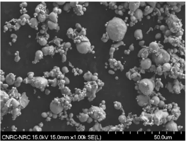
Water-atomized, pre-alloyed 17-4PH stainless steel powder (Grade PF-15F, d50 = 8.0 m, Epson-Atmix Corporation, Japan), shown in Figure 2, was used as base material for stainless steel foam production. The foams were produced using the NRC Process: in the case of the medium porosity foams (MPFs), the chosen binder was a polyethylene powder (Microthene FN 501-00, Chempoint), while the blowing agent was a p-p'-oxybis (benzene sulfonyl hydrazide) powder (Crompton Corporation). A crosslinking agent powder was also added (Dicumyl peroxide, Arkema Inc.) to help in obtaining stable foams. The non-metal components of the high porosity foams (HPFs) were a Resole (i.e. one-step) phenolic resin powder as the binder (Durez Corporation) and p-toluene sulfonyl hydrazide powder as the blowing agent (Crompton Corporation).
Figure 2: SEM Micrograph of the initial, prealloyed 17-4PH powder
In each foam-type case, the powders were weighted to the required proportions and poured in steel cans, along with three 12.7 mm (½”)-diameter steel balls per can, to be blended for 30 minutes using a Turbula mixer.
The homogeneous MPF formulations were poured into a series of cylindrical aluminium moulds (60mm-diameter x 75mm high) and compacted by hand using a 57mm-diameter aluminium cylinder. These were then inserted in a laboratory convection oven and foamed for one hour at 210C in air. After unmoulding, the resulting stainless-steel-charged polymer “prefoams” were then inserted in a Lindberg tubular furnace and submitted to a debinding/pre-sintering cycle: 4.5 h at 450C under a flowing, Ultra High Purity (UHP, 4 ppm O2) argon atmosphere, followed by 1h at 1000°C under flowing re-purified UHP Argon (~1x10-11ppm O
2) obtained by passing UHP argon gas through a Centorr Furnaces/Vacuum Industries Model 2A Gas Purifier. After this treatment, smaller cylinders were machined out of the pre-sintered samples and sintered for 2h at 1200°C under a flowing, 100% H2atmosphere in a Lindberg tubular furnace.
The HPF powder formulations, once blended, were transferred into rectangular stainless steel moulds (100mm x 280mm x 35mm high), lightly compacted and foamed in a laboratory convection oven for two hours at 110C in air. After foaming, cylindrical specimens were machined out of the rectangular prefoam blocks and debinded for 12 h at 550°C in a Lindberg tubular furnace under a flowing 4% O2+ 96% N2atmosphere, and then sintered in a similar furnace under flowing, 100%H2for 2h at 1200°C.
After sintering, half of each type of sintered foam (MPF and HPF) specimens were submitted to the H900 treatment as follows:
Solution Treatment:
• Flowing Re-purified UHP Argon (~1x10-11ppm O 2) • 30 min. @ 1040 ± 15°C
Air Quench:
• Specimens cooled on a copper plate in ambient air Precipitation Hardening:
• Flowing Re-purified UHP Argon (~1x10-11ppm O 2) • 1h @ 482 ± 5°C
Air Cooling:
• Specimens cooled on an aluminum plate in ambient air The porosity level of every as-sintered or H900-treated specimen was evaluated based on mass and dimensions. SEM observations (Hitachi S-4700) were used to characterize the 3D morphology of the stainless steel foams. Micro-Computed Tomography (CT) analyses were carried out using a XTek HMXST 225 System (now Metris) under a voltage of 145 kV and a current of 84 A. Instrumented Indentation Testing (IIT) was carried out using a Nano Indenter G200 (Agilent Technologies) was used for determination of micro-scale mechanical properties (micro-indentation testing). Uniaxial compression testing was performed to evaluate the mechanical properties of the foams at the macro scale. Cylinders, 15 mm in diameter and 22 mm in height for HPFs and 18 mm in diameter and 17 mm in height for MPFs, were used for the compression tests, which were performed on a MTS 100 kN testing machine using a crosshead speed of 1.25 mm/min.
RESULTS AND DISCUSSION
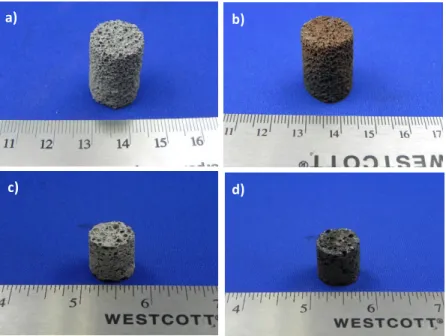
Pictures of foam as-sintered and H900-treated specimens are presented at Figure 3. From these, it is clear that, while the aspect of the as-sintered foams corresponds to that expected from powder structures sintered in an efficient reducing atmosphere, the H900-treated specimens have obviously been oxidized during the two air-cooling phases of the treatment.
Figure 3: Pictures of 17-4PH foams specimens: a) HPF, as-sintered b) HPF, H900 c) MPF, as-sintered d) MPF, H900 a) b) c) d)
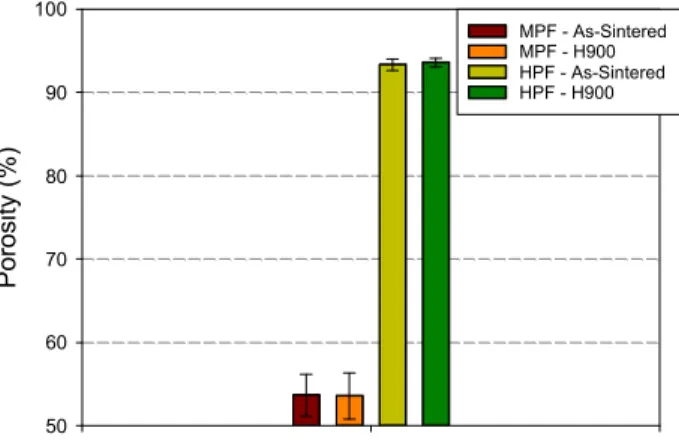
The porosity percentage as determined by foam specimen mass and dimensions is presented at Figure 4. It is clear that HPFs have a much higher average porosity than MPFs (~93% vs ~54%). It is also seen that the H900 treatment has a negligible effect on global porosity percentage. It can thus be expected that the mechanical properties of the MPFs will be significantly higher than those of the HPFs.
Figure 4: Average porosity level (with standard deviation) of 17-4PH stainless steel foams as a function of foam type (MPF and HPF) and state (as-sintered or H900)
The morphology of the two types of foams (as-sintered) can be observed at Figure 5. Even though the magnifications are not identical, the size of the micrographs was chosen so that the ruler was of the same length, thus enabling direct comparison of the foam structures. The H900 treatment did not change the foam structure so no micrograph is shown. While the foams look very different at first glance, they both sport main cells connected together by windows, i.e. holes in the main cell walls. The biggest difference comes from the thickness of their respective walls: the HPF walls are very thin and delicate, featuring a large number of windows, while the MPF structure is made of very thick walls pierced by few windows. In fact, the MPF walls incorporate large pores with diameters close to those of some of the main cells observed in the HPF specimen. A large crack can also be seen within one of the thicker walls of the MPF, but it is not clear whether this crack appeared during foam processing or when the sample was cut to reveal its internal structure. P or os ity ( % ) 50 60 70 80 90 100 MPF - As-Sintered MPF - H900 HPF - As-Sintered HPF - H900
Figure 5: FEGSEM Micrographs of 17-4PH foams specimens: a) HPF, as-sintered
b) MPF, as-sintered
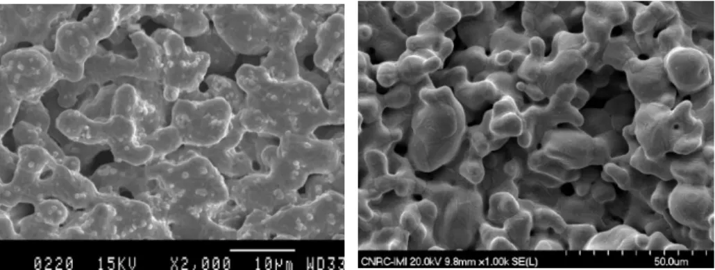
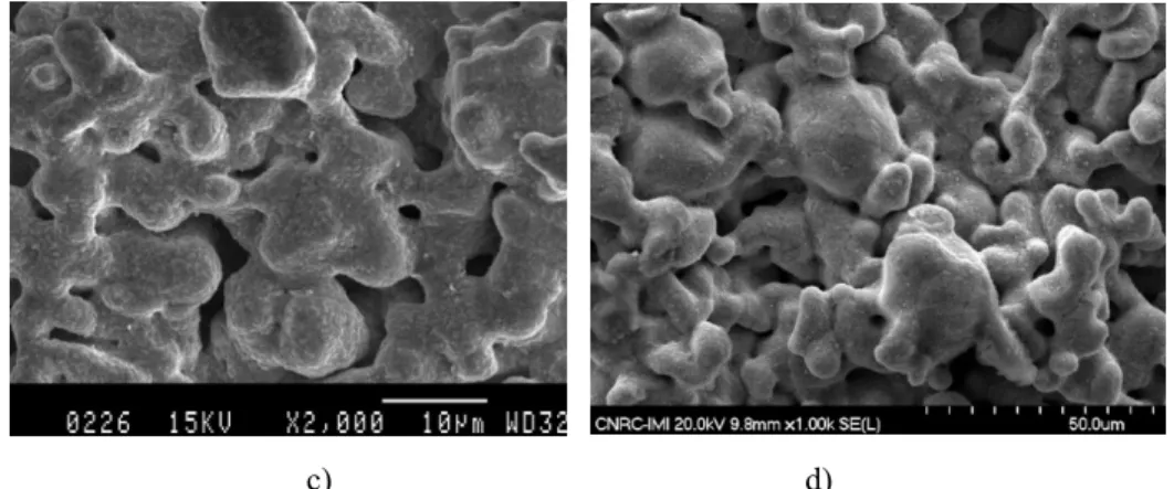
Higher magnification FEGSEM micrographs of these as-sintered foams are shown in Figure 6 a) and b), while the effect of the H900 treatment on the foams’ inner surface can be observed in Figures 6 c) and d). Figures 6a and b clearly show that the 17-4PH particles are very well sintered in both HPFs and MPFs, but also that some inter-particle porosity still exists in each foam structure. After the H900 treatment (Fig. 6c and d), the inner surface of both foams is seen to be different than in the as-sintered state. This is due to oxidation during the air-cooling phases of the treatment. However, the micro-porosity doesn’t seem to have been affected by oxidation (e.g. no apparent clogging, etc.). Figure 7 presents polished cross-sections of specimens of HPF (Fig. 7a) and MPF (Fig. 7b). In these figures, the epoxy resin used for mounting and polishing the foam samples appears brown under optical microscopy (Fig. 7a) and black under FEGSEM (Fig. 7b). These micrographs reveal that, while the differences in wall thicknesses are as clear in 2D as they were in 3D (Fig. 5), the most striking feature is the inter-particle porosity, which is seen to be extensive and distributed all over the volume of the wall cell network of both types of foam. This fine porosity certainly has an impact on mechanical response of both foam types.
c) d)
Figure 6: FEGSEM Micrographs of 17-4PH foams specimens: a) HPF, as-sintered, 2000x b) MPF, as-sintered, 1000x c) HPF, H900, 2000x d) MPF, H900, 1000x a) b)
Figure 7: Cross-sections of 17-4PH foams specimens: a) HPF, as-sintered / optical micrograph (100x) b) MPF, as-sintered / FEGSEM micrograph (50x)
Micro-Computed Tomography (CT) analyses of as-sintered MPF and HPF specimens enabled the generation of ten 2D slices parallel to the radial axis per foam type (as the H900 treatment didn’t change the pore size, no results are shown for these materials). These pictures were then submitted to an image analysis routine so that the pore size distribution of the main cells and other large pores (excluding windows) could be quantified. The pore size distributions of specimens of each foam type, along with representative CT slices, are presented at Figure 8. The HPF pore diameters follow a near-normal distribution, with a d50of about 700 m, and appear quite homogeneous. In the case of the MPF specimen, its inhomogeneous pore distribution features some very large cells (Fig. 8d) which skew the distribution to the larger pore sizes, resulting in a d50 of ~1100 m.
a)
b)
c)
d)
Figure 8: Pore Size Distribution with d50 value of as-sintered 17-4PH foams specimens: a) HPF Pore Size Distribution
b) HPF 2D cross-section generated from CT data c) MPF Pore Size Distribution
d) MPF 2D cross-section generated from CT data
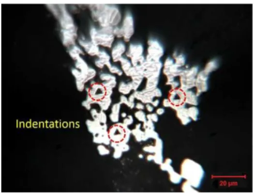
The micro-scale, mechanical properties of the HPF and MPF foams were measured using a nanoindenter as the size of the indentations had to be very small due to the porous nature of the foam cell walls and the fine size of the sintered particles (Figure 9). The conventional mode was used for indentation testing in the case of HPFs, while the MPFs were tested in the Continuous Stiffness Measurement (CSM) mode. In both cases, the elastic modulus and microhardness of the foams were evaluated for specimens in the as-sintered and H900-treated states. The results are shown in Figure 10. In the case of the elastic modulus (Fig.10a), it is observed that the MPFs have an indentation modulus close to that of 17-4PH wrought material [11], while the modulus of the HPFs is much lower and appears to increase with the H900 treatment. The latter may be due to a stronger heat treatment effect caused by the very small thickness of the cell walls and their high porosity.
d
50 700 m
Figure 9: Micrograph showing triangular indentations in HPF cell wall
b)
Figure 10: Indentation Testing Results for 17-4PH foams specimens with modulus [11] and hardness [12] values from the Literature:
a) Elastic Modulus b) Microhardness
The microhardness results (Fig.10b) indicate that the H900 treatment seems to have a positive impact on the indentation hardness for both foam types, the greatest increase being measured for HPFs. Once again, the very thin wall sections of the HPFs could possibly explain this higher strengthening effect. However, in this case and that of the above modulus measurements, the size and distribution of the copper precipitates would have to be characterized by advanced microscopy techniques (e.g. TEM) to verify this hypothesis. Nevertheless, given the current results, it is clear that the average values obtained for both foams are reasonably close to those of Metal Injection Moulded (MIM) 17-4PH components taken from the literature [12].
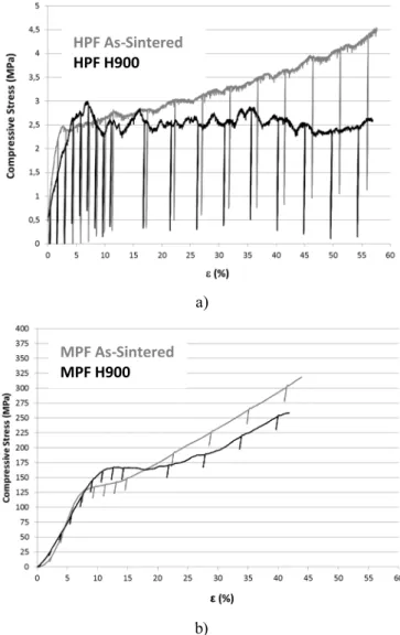
Typical compression curves are presented at Figure 11 for HPF and MPF specimens. In Figure 11 a) and b), the slightly diagonal lines under the compression curves are unloadings carried out so as to measure the elastic modulus as is generally done for metal foams [4]. First of all, a comparison between the HPF and MPF curves shows the very large difference in compressive strength between the two foam types. As could be expected from their differences in porosity level and morphology (wall thickness), the MPFs are much stronger than their HPF counterparts. For both foam types, the H900 treatment is seen to result in a more brittle behaviour, the H900 curves being less smooth than those of the as-sintered materials. This is coherent with the effect of precipitation hardening on bulk 17-4PH, i.e. an increased hardness and decreased elongation (ductility) [13].
The compressive properties of the 17-4PH foams are compiled in Table 1. Looking at the properties of 17-4PH foams from the current study, it is clear that the average compressive yield strength (y,c) and average modulus (E) of HPFs, given their rather large standard deviations, seem to be unaffected by the H900 treatment. In the case of the MPFs, the average modulus seems unchanged (in fact, it is very similar), while there
appears to be an increase of average y,c. However, the standard deviations on the yield stress values are also quite large, so care must be taken in the interpretation of this result.
The y,cvalue from Raj et al [6], which was obtained for a 94% porous foam which had been submitted to the H1025 treatment, can be compared with those acquired for HPFs as their porosity levels are similar (~94%). It can be seen that the compressive yield strength values from the two studies are in very good agreement.
Other values were extracted from the work of Mutlu and Oktay [8]. These are for 17-4PH foam porosities of 50, 70 and 80% (their 17-4PH foam formulations also contained 0.5wt% Boron as a liquid-forming phase, i.e. as a sintering aid). In their paper, the results of the H900 treatment were only presented for the 70% specimen. However, the value at 50% porosity can be compared to the one obtained in the current study, while the values for 70 and 80% porous foams can help in determining the decreasing trend of y,cvalues for increasing foam porosities.
a)
b)
Figure 11: Compression curves of 17-4PH foams specimens: a) HPF, as-sintered vs H900 b) MPF, as-sintered vs H900 HPF As-Sintered HPF H900 MPF As-Sintered MPF H900
Table 1: Average Compressive Properties of the 17-4PH Foams (with Standard Deviations) From This Study and From References [6] and [8]
State Porosity (%) y,c (MPa) E (GPa) HPF As-Sintered 93,3 ± 0,7 3,19 ± 0,82 8,51 ± 1,15 H900 93,6 ± 0,5 3,05 ± 1,13 7,18 ± 2,36 MPF As-Sintered 53,7 ± 2,5 135,50 ± 23,19 40,43 ± 10,32 H900 53,6 ± 2,8 166,70 ± 37,63 40,48 ± 9,77 Raj [6] H1025* 94 ~2.8 N/A Mutlu [8] As-Sintered** ~50 ~165 N/A Mutlu [8] As-Sintered** ~70 ~60 N/A H900** ~70 ~65 N/A Mutlu [8] As-Sintered** ~80 ~50 N/A
* Solution annealed 60 min. @ 1036°C, then age-treated 90min. @ 552°C // E value not available
**17-4PH + 0.5wt. % Boron, Sintered 40 min. @ 1260°C // E not reliable as was not measured using the unloading method [4] At 50% porosity, the as-sintered 17-4PH foam from ref. [8] has a y,cvalue of about 165 MPa. This is very close to the one evaluated for H900-treated MPF in the current study (~167 MPa) and is almost within the standard deviation of the as-sintered MPF. At 70% porosity, Mutlu’s as-sintered value of y,c(60 MPa) increases to 65 MPa when H900-treated. This is a rather modest increase when compared to the ~ 31 MPa augmentation for this study’s 54%-porous MPF specimens. However, increasing Mutlu’s foam porosity to 80% decreases the y,cvalue only to 50 MPa, while the 94% porous HPFs of the current work have a compressive yield stress on the order of 3 MPa. A higher y,cvalue could thus be expected for Mutlu’s foams at 94% porosity unless some unidentified phenomenon brings it down more quickly for porosities over 80%. The fact that a boron addition was made to 17-4PH in [8] probably resulted in much denser cell walls (see Fig.6 in ref. [8]) than those of the current work, which are very porous (Fig.7). This could explain the higher
compressive yield stress values obtained in reference [8] as compared to those of the current study.
CONCLUSION
Open-cell, 17-4PH foams with medium and high porosity (MPFs and HPFs) were produced using the NRC process starting from a pre-alloyed powder and the effect of a subsequent H900 precipitation hardening treatment on the structure and properties of these foams was studied. The porosity level, surface state and pore size distribution of the two foam types were not affected by the strengthening treatment.
The MPFs had much higher mechanical properties than the HPFs. At the micro scale, the H900 treatment appeared to have a more pronounced impact on the properties of the HPFs than on those of the MPFs. This was probably due to a higher heat treatment response of the HPFs caused by their very thin wall sections, but this would have to be further investigated. At the macro scale, the H900 had a qualitative effect on the compression stress vs strain curves, a more brittle behaviour being observed for heat-treated foams of both types over their as-sintered counterparts. A comparison between the compressive properties of foams from this work and data from the literature has shown reasonable agreement in the case of compressive yield stress values. However, the large scatter in y,cvalues from the current study, coupled with the processing/compositional differences of 17-4PH foams from the literature, indicate that any direct comparison between these foams must be made with caution.
References
[1] M.A. Atwater, L.N. Guevara, K.A. Darling, and M.A. Tschopp, Adv. Eng. Mater. 20, paper no. 1700766 (2018).
[2] J. Banhart, Adv. Eng. Mater. 15, 82-111 (2013).
[3] Louis-Philippe Lefebvre, John Banhart and David C. Dunand, Adv. Eng. Mater. 10, 775-787 (2008).
[4] M.F. Ashby, A. Evans, N.A. Fleck, L.J. Gibson, J.W. Hutchinson, H.N.G. Wadley, Metal
Foams: A Design Guide (Butterworth Heinemann 2000).
[5] Isabel Duarte, Mónica Oliveira, «Aluminium Alloy Foams: Production and Properties», in
Powder Metallurgy, Katsuyoshi Kondoh, IntechOpen, DOI: 10.5772/34433. Available
from: https://www.intechopen.com/books/powder-metallurgy/aluminium-alloys-foams-production-and-properties(2012).
[6] S.V. Raj, L.J. Ghosnb, B.A. Lerch, M. Hebsur, L.M. Cosgriff, J. Fedor, Mater. Sci. Eng. A.
456, 305-316 (2007).
[7] H. Ö. Gülsoy and R. M. German, Powder Metall., 51, 350-353 (2008). [8] I. Mutlu, E. Oktay, J. Porous Mater. 19, 433-440 (2012).
[9] L.J. Gibson, Annu. Rev. Mater. Sci. 30, 191-227 (2000).
[10] L.P. Lefebvre, Y. Thomas, «Method of Making Open Cell Material», US Patent 6,660,224 B2 (2003)
[11] Stainless Steel - Grade 17-4 (UNS S17400) Datasheet,
https://www.azom.com/article.aspx?ArticleID=6778
[12] Kinetics, Inc. Technical Data Sheets,www.matweb.com
[13] J. Douthett, « Heat Treating of Stainless Steels», in ASM Handbook, Volume 4: Heat Treating, ASM International, 769-792 (1991).
![Figure 10: Indentation Testing Results for 17-4PH foams specimens with modulus [11] and hardness [12] values from the Literature:](https://thumb-eu.123doks.com/thumbv2/123doknet/14034752.458506/12.648.96.528.73.404/figure-indentation-testing-results-specimens-modulus-hardness-literature.webp)
![Table 1: Average Compressive Properties of the 17-4PH Foams (with Standard Deviations) From This Study and From References [6] and [8]](https://thumb-eu.123doks.com/thumbv2/123doknet/14034752.458506/14.648.58.571.124.664/table-average-compressive-properties-foams-standard-deviations-references.webp)
