Touch Lab Report 3
Determination of Mechanical Properties of the Human
Fingerpad In Vivo Using a Tactile Stimulator
Rogeve
J. Gulati and Mandayam A. Srinivasan
RLE Technical Report No. 605
January 1997
This work was supported by the Office of Naval Research under Grant N00014-92-J-1814.
The Research Laboratory of Electronics
MASSACHUSETTS INSTITUTE OF TECHNOLOGY
CAMBRIDGE, MASSACHUSETTS 02139-4307
Determination of Mechanical Properties of the Human
Fingerpad, In Vivo, Using a Tactile Stimulator
Rogeve J. Gulati
Boston University, College of Engineering, 1995
Mandayam A. Srinivasan Principal Research Scientist
Department of Mechanical Engineering Research Laboratory of Electronics Massachusetts Institute of Technology
H. Steve Colburn Professor of Biomedical Engineering
Boston University
Abstract
A desire to better understand the mechanics of the human fingerpad, in vivo, as related to haptic performance and tactual perception prompted an investigation of the fingerpad's characteristic force response to indentation. A computer-controlled, high-precision tactile stimulator was constructed to deliver a combination of uniaxial static, ramp and sinusoidal indentations normal a specific region of the stationary and passive fingerpads of five different subjects. Both input indentation depth and fingerpad force response were recorded as a function of time to capture transients and steady state features. Three aluminum indentors, a point, a 6.35 mm diameter circular probe and a flat plate, were used for indentation to represent three general classes of loading profiles encountered in manual exploration and manipulation. With each shape, repeatability of the response was tested and the effects of varying amplitude, velocity and frequency of indentation were investigated.
The experiments revealed that the force response of the fingerpad is both nonlinear and viscoelastic with respect to indentation depth and velocity. A clear variation was present in the force response among the five subjects tested and across the three different indentors. This variation was minimized partly by determining a subject specific parameter with which to normalize the force response data. A nonlinear Kelvin model was then proposed to mathematically represent this characteristic force response of the fingerpad to indentation as a function of indentor and subject. However, in implementation, the nonlinear model was approximated by a lumped parameter model composed of a piecewise linear set of springs in parallel with series spring-dashpots. Parameters were estimated for the model for each subject and indentor given the experimental input and normalized output data. These "individual" models were able to predict data for that particular subject and
indentor very well (R2 > 0.96) but not as well for others. The means of the parameters
across subjects were further utilized to construct more general, indentor specific versions of the model, which were only slightly worse at predicting force response to some given indentation.
Table of Contents
Chapter 1: INTRODUCTION 1
1.1 The Mechanics of Touch 1
1.2 Previous Research 4
Chapter 2: STRUCTURE OF THE FINGERTIP 7
2.1 The Fingertip 7
2.2 The Pulp 9
Chapter 3: INITIAL DESIGN CONSIDERATIONS 12
3.1 Linear Actuation and Position Encoders 16
3.2 Force Sensor Requirements 18
Chapter 4: TACTILE STIMULATOR 21
4.1 Overview of System Components 22
4.2 Robot Manipulator Design 23
.3 Joint Angle Position Encoders 27
4.4 Motors, Amplifiers and DA Output 30
4.5 Timer Board and Velocity Measurement 31
4.6 Proportional Derivative Control 32
4.7 Inverse Kinematics 34
4.8 Two-Axis Force Sensor 38
4.9 Final Design Issues and Assembly 47
Chapter 5: DESIGN OF EXPERIMENTS 49
5.1 Indentor Geometries 49
5.2 Indentation Stimuli 50
5.3 Experimental Setup 53
5.4 Preliminary Experimental Protocol 55
5.5 Experimental Protocol 57
Chapter 6: EXPERIMENTAL RESULTS 59
6.1 Subject Data 60
6.2 Processing the Experimental Data 62
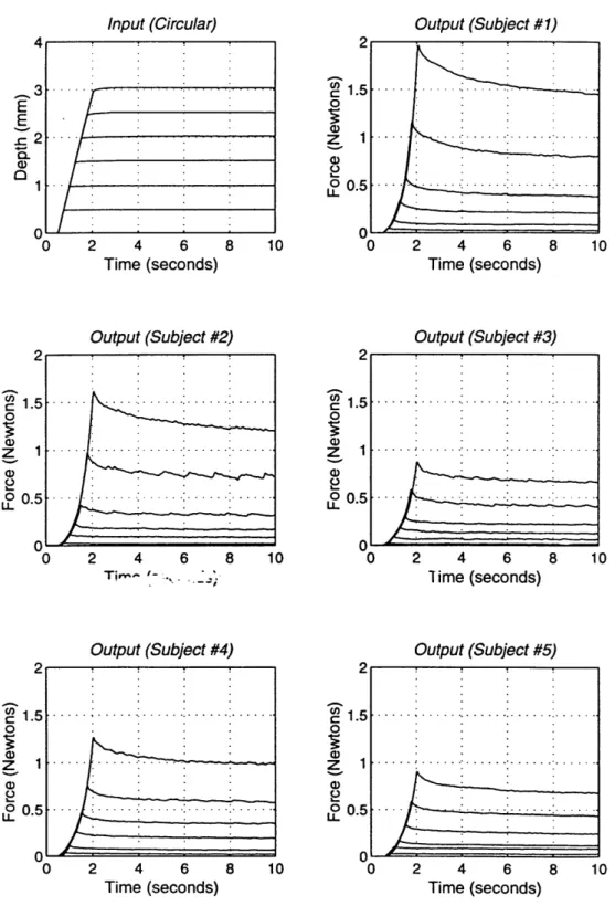
6.3 Ramp/Hold Experimental Results 65
6.4 Sinusoidal Experimental Results 81
6.5 Hysteresis Representation of Dynamic Results 86 6.6 Discussion of Results and Conclusions Drawn 93
Chapter 7. MODELS OF THE MECHANICAL RESPONSE 96
7.1 Viscoelastic Linear Models 97
7.2 Refining the Kelvin Model 99
7.3 The Piecewise Linear Kelvin Model 103
Chapter 8: CONCLUDING REMARKS 120
Appendix A: STIMULATOR CODE 124
Appendix B: SINUSOID RESPONSE DATA 140
Appendix C: HYSTERESIS CURVES 201
Appendix D: HYSTERESIS SLOPE AND PERCENTAGE AREA 217
Appendix E: MATLAB PROGRAMS 223
Appendix F: MODEL VS. EXPERIMENTAL DATA 233
Appendix G: GENERAL MODEL VS. EXPERIMENTAL DATA 249
References 265
S
A--Chapter 1
Introduction
1.1 The Mechanics of Touch
The mechanical behavior of the fingerpad tissues plays an important role in the perception of physical properties (e.g. shape and texture) and in control of contact conditions during tactual exploration or object manipulation. Mechanical behavior refers simply to the force response characteristics of the fingerpad as a material to deformation. And "fingerpad" refers to a specific region of complex, nonhomogeneous, anisotropic soft tissue on the palmar side of the distal phalanx, its surface distinguished by concentric ridges that form unique fingerprint patterns. Distributed within the distinct layers of hairless, palmar skin and underlying subcutaneous tissues are the sensory nerve endings called mechanoreceptors that respond to the spatial and temporal properties of loading on the fingerpad. Each type of receptor is sensitive to particular features of the contact conditions (e.g. vibration, fluttery motions) and transmits information to regions of the brain such as the sensorimotor cortex where a "tactile image" can be formed. In the absence of auditory and visual sensory cues or inputs, many object properties can be determined based on the tactile sense alone. This thesis focuses on the simplest,
one-dimensional case of relating loads on the fingerpad at the contact interface to the associated fingertip deformation.
Modeling the mechanical behavior of the fingerpad has impact in both understanding all of the physical mechanisms involved in human tactile sensing as well as the improvement of contact interactions with haptic tools and devices. Because the basic, characteristic response of fingerpad affects first the stress/strain distribution in the skin and subcutaneous layers and subsequently the intensity of tactile receptor response, simple mechanical models lay foundations for more advanced research of touch biomechanics and neurophysiology. During manual interactions with devices (e.g. robots, virtual environment haptic interfaces, prosthetics and tactile aids for the blind), the mechanical behavior of the fingerpad also influences the perception and control of parameters such as slip, compliance, grip force and viscosity at the contact interface.
Whenever we touch an object, the source of all tactile information is the spatio-temporal distribution of mechanical loads on the fingertip skin at the contact interface. (Srinivasan, 1992). The loads or pressure distributions along the palmar surface of "fingerprint" skin create time varying stress and strain densities within the skin and subcutaneous layers. Rapidly adapting and slowly adapting receptors, well-placed and oriented within the fingerpads, relay this stress/strain information to the brain, where a tactile image is formed that describes shape, texture, temperature, etc. of the object or material being explored. At the neurophysiological level, studies are being conducted on the afferent neural response to static and dynamic loadings (e.g. Johnson and Hsaio, 1992; Srinivasan and LaMotte, 1987). Direct measurement of stress/strain rates and densities at receptor sites, though, is not presently possible (Srinivasan, 1992). This information can be provided instead by three-dimensional computer based finite element models (FEM) of the fingertip which match its material and mechanical behavior. In practice, an FEM of a fingerpad indentation response can be verified against real in vivo 2
biomechanical data. This effort requires extensive investigation of the characteristic mechanical response of the fingertip and the acquisition of real-time data on subjects who vary in size, shape, stiffness, etc.
Modeling the fingertip's mechanical behavior is also a strong asset to better understanding haptic control and improving the design and development of haptic interfaces. Contact conditions during manual manipulation and exploration are inherently affected by the mechanical properties of both the object(s) in contact and the soft tissues of the fingerpads. Perception of slip and control of grip force are two examples where the mechanics of the fingerpad plays a direct physical role in haptic performance. By modeling the force response under deformation, we begin to better comprehend the mechanisms involved in controlling and perceiving those contact conditions.
In summary, it can be said that a thesis of this kind will provide a valuable and necessary building block for the understanding of the human sense of touch. It will perhaps see direct application in the design of simple haptic interfaces that simulate mechanical behavior of objects (e.g. various types of switches and buttons). The next few chapters present some anatomical and physiological background and the development of an experimental device, "tactile stimulator." Its implementation in recording the in vivo force response of the human fingerpad to precise deformations under three different indentor shapes is discussed next. Based on this data for several subjects, a sequence of linear and nonlinear models that fit the characteristic response with increasing precision are proposed, discussed, and refined to produce the most generalized model that appears reasonably valid for all the subjects tested.
1.2 Previous Research
The mechanics of the human fingerpad and the properties of skin and soft tissues,
in vitro, have been topics of investigation for many years, but it is apparent that only in
the last few decades have major steps been taken to focus the study in vivo. An extensive search of literature established the dominance of in vitro research on tissue mechanics. This is likely due to the greater ease of material tests, in vitro, on an isolated and separated skin or tissue sample. Interest in the sense of touch, though, requires understanding of the bulk material properties of the fingerpad as a whole. In vivo study of any anatomical and physiological properties of the body certainly provide much greater challenges. The noninvasive data that is available on skin in combination with its attached underlying tissues has been focused more on sections of the body such as the thigh and forearm, as opposed to the fingerpad "pulp." These experiments are often limited to high frequency response and skin impedance. Consequently, the lack of in vivo data on the mechanical properties of the passive human fingerpad prompted study of its characteristic force response to deformation.
Several papers represent the pool of in vivo studies performed. Finlay (1970) "glued" probes to skin at several locations on the body and imposed rotational vibrations at 1 Hz in an effort to characterize impedance of the skin. However, in his experiments, sinusoidal stimuli were given to hairy (dorsal) regions of skin not inclusive of the fingerpad, and he was concerned with the response to skin "stretch" as opposed to indentation. The results demonstrated a nonlinear response to dynamic, torsional skin stretch in the human forearm and thigh. But, Finlay himself makes the important observation relevant to this study that "if...a surgeon wishes to have information on the mechanical properties of skin in a given area, then he must conduct specific tests in that
area." Lanir (1990) performed indentation experiments on human forehead skin to show the effects of aging. Indenting from 0.2 to 1 mm with a circular Teflon probe of 0.2 cm2, he discovered that indentation increases exponentially with loading pressure from 0 to 5 kPa. Though the forehead tissues are structurally distinct from the fingerpad, the findings were indicative of a nonlinear indentation response in the skin and its underlying tissues. Other papers explore mechanical impedance (Franke, 1950; Von Gierke et al., 1951), shear wave propagation (Pereira et al., 1989; 1991) and dynamic in vitro testing of skin (Veronda and Westmann, 1968; Pereira et al., 1990). In vitro and in vivo tests for compressibility have implied that human skin is incompressible (e.g. North and Gibson, 1978), however, the MIT Touch Laboratory's in vivo tests for compressibility on the human fingerpad have yielded results that imply the fingertip is compressible to some degree (Srinivasan et al., 1992). Petit and Galifret explored force versus indentation in the rat and man, including the human fingerpad in their investigation (Petit and Galifret, 1978). For indentations up to 1 mm, they presented an exponential relationship between deformation and loads (up to 0.04 N). Also noted were (1) periodic "tremors" in the skin due to respiration and proximity to blood vessels and (2) a relaxed rate of reformation to the original shape after indentor removal (viscoelasticity). The investigation was limited in scope with respect to specific fingerpad mechanics and did not provide enough data for the modeling proposed in this paper. Moore and Mundie (1972) performed another study on the static force of the skin-tissue system relating to the tactile regime, but the data is also of limited extent and makes few specific claims about the characteristic mechanical response of the fingerpad. Reactance as a function of probe area and static pressure is discussed and analyzed over a range of frequencies from 10-750 Hz, but the little data shown does not appear to be leading toward mechanistic models. In fact, it can be confidently stated that all of these studies and others like them are concerned with areas of the primate or animal body other than the fingertip, are far from conclusive about
characterizing force as a function of loading or are in vitro, which, at best, serve only as a foundation for additional research.
Reliable, repeatable data on the force response of the human fingerpad to various types of static and dynamic stimuli is not yet available en masse to provide for viscoelastic linear or nonlinear modeling of the fingertip. The next chapter offers a short description of the fingerpad, leading into a discussion of the "tactile stimulator," experiments performed and a presentation and analysis of data, as well as models of the force response to indentation with three separate probes.
Chapter 2
Structure of the Fingertip
2.1 The Fingertip
The hand is one of the most complex structures of the human body in terms of both sensory acquisition and motor control. Close to a quarter of the sensorimotor cortex is dedicated to its control and to tactile processing (McMahon, 1984). And the fingertips, the primary source of tactile information, contain the mechanoreceptors that facilitate touch. A finger is represented in Figure 2-1, showing its macroscopic features--the outline of the skin, bone and nail.
Fingerpad
Skin
Subcutaneous Tissues
Bone Nail
Bone
Figure 2-1: Cross-section of the human finger.
The bone and nail can be assumed to be completely rigid, relative to the softness of the bulbous fingerpad and the magnitude of forces involved in typical manual interactions .
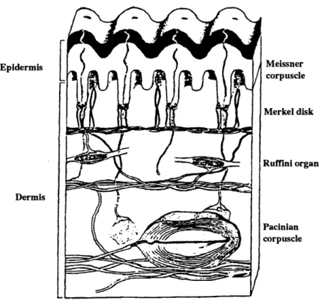
Thus, this study focuses only on the skin and subcutaneous tissues that comprise the "pulp" (Thomine, 1981). In general, skin is a complex, multilayered organ composed of the epidermis and dermis (Lanir, 1989). The skin of the fingertip is thick, the epidermis being close to 1.0 mm (Quilliam, 1978). The dermis is rich in nerve endings and uniquely organized with features such as the dermal papillae, tendrils of tissue that push up into pockets of the epidermis (Quilliam, 1978). A schematic of skin is shown in Figure 2-2. Epidermis Dermis Meissner corpuscle Merkel disk Ruffmni organ Pacinian corpuscle
Figure 2-2: Cross-sectional view of fingertip skin, showing papillary
ridges and the embedded receptors (Darian-Smith, 1984).
The underlying subcutaneous tissue is composed primarily of fat cells that are enmeshed to give the finger its firm, rounded outline. They also contribute to the fingertip's elastic,
cushion like ability to adapt to the shape of an object snugly and to reform easily from such deformations (Quilliam, 1978).
2.2 The Pulp
In studying the mechanical properties of the fingertip as they relate to tactile sense, a specific focus is made on the pulp, the palmar region of the distal phalanx (Thomine, 1981). The pulp of the fingertip is bordered by the edges of the nail, the junction of palmar and dorsal skin and the distal interphalangeal groove. Its composition includes hairless palmar skin and underlying fatty tissue, described briefly above. Palmar skin is distinctly characterized from the more prevalent dorsal skin by a thick epidermal layer and the dermal papillae, as shown below in Figure 2-3.
Figure 2-3: A comparison of palmar (left) and dorsal skin (Quillam, 1978).
The epidermis of the palmar, fingertip skin is notably thick. It is composed of four distinct layers. Deepest is the basal layer, formed of basal cells, melanocytes and
collagen or reticular fibrils, which fasten the epidermis to the dermal layer below. Next is the malphigian, a thick multicellular layer responsible for skin regeneration and cellular multiplication. Above that is the granular layer, which is only 2-3 cells thick and is enhanced by active keratinization, or the buildup of keratin within the cell walls as cell death occurs. The horny layer is the most superficial, composed of highly compressed, flattened cells. Also present in the palmar epidermis is the stratum lucidum, a thin oil-rich layer between the granular and horny layers. Skin regeneration occurs continuously, as cells migrate from deeper layers to the most superficial where they eventually die and "flake off."
The dermis is made up of connective tissue with intertwining collagen, elastin and reticular fibers, as well as some cells, blood vessels and nerve endings. A notable feature of the palmar dermis is the presence of papillary ridges, seen previously in Figure 2-2, which push up into and help shape the epidermal layers. In the fingerpad, the ridges formed by the epidermal and dermal layers take a concentric pattern to form the fingerprints. Within the folds of the ridges can be found the Merkel's Discs and Meissner's Corpuscles, tactile receptors that respond to light touch and fluttery motions, respectively. The subpapillary dermis contains the larger Ruffini's Corpuscles, which respond to skin stretch.
Below the dermis lies a thick, cushion-like layer of fatty tissue or subdermal adipose. The Pacinian Corpuscles, large, rapidly adapting receptors that respond to high frequency vibration (greater than 200 hz) reside here.
In summary, the pulp is multilayered and nonhomogeneous, and all aspects of its structure can play an crucial role in tactile sense. For instance, the arrangement of receptors within the papillary ridges allow finer touch discrimination when stroking an object. Similarly, the thick, cushiony subdermal adipose layer's tendency to conform to the object allows improved discrimination of shape. Each of these physical features in 10
turn affects the distributions of stresses and strains during loading due to a deformation. The pulp's mechanical properties are, therefore, a critical feature of the sense of touch and haptic control. For purposes of this research, the entire pulp is viewed as a nonlinear, nonhomogeneous block of material whose mechanical properties as a whole need to be identified quantitatively.
Chapter 3
Initial Design Considerations
The primary goals of this project were (1) to acquire in vivo data on the force response of the fingerpad to diverse displacement-controlled, static and dynamic indentation profiles and (2) to characterize this data with a model normalized to fit the mechanical response of any given finger. To realize these goals, it was important to understand both the basic features of the response of the "pulp" to indentation and aspects of the models that would be used to simulate those responses. The fingerpad, a 4-5 mm thick region of tissue, blood vessels and receptors, has been shown to be comprised of several distinct layers, each with unique properties--from the hard, flaky outer epidermal layers to the cushion-like subdermal adipose. Under in vivo conditions, the pulp exhibits properties during and after indentation that clearly characterize its viscoelastic nature. If indented, the fingertip responds with force that increases monotonically to indentation depth like a stiff spring element. However, when unloaded (indentor removed), the viscous nature of the fingerpad becomes obvious. The pulp relaxes to its original shape at some rate slower than the initial deformation. It was inferred from these features that models of the fingertip will include "springs" and "dashpots", elements which produce forces in response to deformations and deformation rates, respectively.
The extent of modeling performed before the construction of a tactile stimulation device to conduct experiments was limited primarily by the lack of real, in vivo data on the mechanics of the fingerpad. However, as noted above, it was reasonable to propose a model combining spring (elastic) and dashpot (viscous) elements. Three basic, viscoelastic spring-dashpot models that are common to the study of biological tissues are shown in Figure 3-1. These models do not attempt to account for effects of the inertia of the tissue mass. However, because the tissue mass is relatively small, there was no preliminary indications that it would play a significant role in the force response characteristics.
Lf
(a) (b) (c)
Figure 3-1: (a) Voigt model, (b) Maxwell model, (c) Kelvin model
Previous researchers of biological tissues have found that the Kelvin model is the lowest order model to match well the mechanical properties of living tissues (Fung, 1990). These issues are discussed in much greater detail after an analysis of experimental results (Chapter 7), where nonlinear elements and the contribution of mass are also investigated. It was enough at this stage to state that experimental, displacement-controlled inputs had to be varied in terms of both depth and velocity to best characterize all the features of fingerpad mechanics.
The resultant force response of the fingerpad will also be influenced by the shape and associated contact area of the probe providing indentation. To elaborate, this is treated as a basic problem in mechanics. The fingerpad, a "block" of viscoelastic material, is viewed most simply as a "bed of springs." If the total area of contact at the probe-skin interface is increased, the number of springs compressed increases as well. Similarly, if one thinks of the finger as a compressible fluid-filled membrane or balloon (Srinivasan, 1989) there is a significant difference between the profile of indentation with a point as opposed to a plane. In both situations, total resultant force of the fingerpad is dependent upon both size (contact area) and shape of the indentor. The conclusion was that indentor shapes would have to be varied sufficiently in order to completely characterize the general force response to deformation.
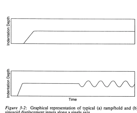
With some basic goals for experiments laid out, the requirements for an experimental device were determined in terms of the approximate ranges and accuracies of position and force control. It was decided that a device capable of providing displacement input and measuring force output was necessary. The range of motion was determined to be more than half a centimeter (the thickness of the pulp) with at least 50 microns of accuracy (10%, assuming increments of indentation of 0.5 mm). The velocity range was estimated to be 0-80 mm/sec, allowing inputs from slow ramps to an approximate step. And, for periodic waveform inputs, a range of 0-20 Hz was chosen for the current study. One justification for this is that during active exploration or manipulation of objects, humans can control their actions to at most 10 Hz (Brooks, 1990), which makes this a limited but practical range for investigation. In all, this covered a wide range of velocities, accelerations, and frequencies. Expected traces of indentation inputs as functions of time are shown in Figure 3-2, where ramp velocity and depth and sinusoid starting depth, frequency and amplitude could be varied sufficiently to produce enough data for modeling.
- C-ci) 0 C 70 c V, _-a) 0 C 0 Is c V Time
Figure 3-2: Graphical representation of typical (a) ramp/hold and (b)
sinusoid displacement inputs along a single axis.
In addition to its precision and dynamic requirements, the device also needed to be capable of delivering (and measuring) adequate forces to indent the finger "smoothly" over the full span of velocities, from a slow ramp to a pseudo-step. The range of "normal" forces were quantified experimentally with a multiple axis strain gage force sensor. For indentations of 4 mm with circular probes of 6.35 mm diameter, forces up to 3 Newtons were measured at the indentor-skin interface. Similar preliminary tests at various depths indicated that a resolution on the order of 0.01 N was necessary to capture fine differences between varied loading conditions. In the following section(s), several types of motion actuators and position encoders are discussed. Following that, additional force sensor requirements are briefly described.
15
-3.1 Linear Actuation and Position Encoders
The first choice made in selecting actuators was to use direct-current motors over alternating-current to produce precisely controlled input indentations. AC motors are more efficient in terms of power consumption and can offer higher speed characteristics. However, they are also designed for single, synchronous speed, high horsepower operations. Variable speed performance can be achieved by alternating the frequency of the power supply or varying the pole and winding architecture. Controlling frequency modulation, though, becomes significantly complicated in high speed motor applications, and there are practical limits to the number of speeds that can be obtained by modifying the ratio of poles and windings. Additionally, AC motors experience a torque ripple that is not easily accounted for by controllers. The device used for the experiments discussed in this thesis needed to be capable of easily varied speed and fast braking accelerations and decelerations. Some of this was shown in the proposed stimuli plotted in Figure 3-2. In its primary mode of indentation, high torque to inertial ratios and low torque ripple or cogging were also required to accentuate the smoothness of motion against higher resisting forces of the finger. DC actuators were the best apparent solution, and are well-accepted practice in small robotics applications such as this one. Some DC actuators are discussed in the rest of this section.
The first type of actuator considered was a DC linear lead screw stepper motor. These actuators have the advantage of higher position resolution and noncumulative error in real accuracy. However, stepper motors in general experience vibration and/or cogging during the actual phase of motion, especially at lower velocities. An inherent mechanical vibration can be expected with any type of lead screw mechanism, which by definition involves contact (and friction) of moving and static metal components. In
addition, their highest load performance is inversely proportional to the velocity of motion. Stepper motors are, however, efficient at accelerating a load and have high braking torques when continuously energized. Some of the basic problems can be diminished by operating with a microstepping controller, which effectively decreases step size by an order of magnitude or more. This has the effect of eliminating some degree of the vibrations during motion and greatly improving position accuracy. In addition, microsteppers improve torque vs. speed performance. The extent to which vibrations can be decreased or filtered out at low velocities, however, did not seem sufficient for performing smooth, continuous sinusoidal inputs (refer again to Figure 3-2) over the full range of frequencies and amplitudes.
Brushless linear DC motors were a more viable option for the smooth type of control desired along one axis. As stated in Machine Design's Annual 1991 index, these motors can be "extremely stiff, fast and efficient" with very high position accuracy that will not deteriorate over time. In fact, high-performance brushless, linear actuators are available from companies such as AnoradT M which can provide relatively smooth motion
with adequate load performance at high velocities. However, these packages tend to be very expensive (over $20,000 for 2 to 3 DOF), which was not within a reasonable budget set for the first attempt at these experiments. Lower cost linear motors have cogging problems, which affects smoothness of motion in a manner similar to the vibrations that would be experienced by lead screw steppers or brushed motors. Cost, unfortunately, became the determining factor in not exploring these motors further.
What was also seen during this investigation is that there are many more rotary types of motors than linear on the market, and it became apparent that a multi-joint linkage, actuated by rotary motors could be a better solution than higher cost linear motors. This option has all of the general benefits of DC motors (e.g. variable speed, fast braking, high accelerations), and rotary type motors tend to be available in a wider variety 17
of torque characteristics at much lower prices. Conveniently, a device designed and built by Professor Robert Howe at Harvard University for use in teleoperation research was available for this project, saving some of the additional time required for design and development. It utilizes a linkage mechanism, operated by two brushed DC motors that allows smooth motion in two axes (Howe, 1992). Though it was obvious that some modifications would have to be made to adapt the device to the needs of these experiments, it seemed an easily realizable and inexpensive a solution to creating the experimental apparatus, since the motors were capable of reasonably high velocities and good power characteristics (torque vs. speed).
Complementary to the search for actuators, several types of the rotary position sensors were investigated as well. These included optical encoders, magnetic encoders, resolvers, potentiometers, and rotary inductosyns. While each was found to have its own advantages and disadvantages, potentiometers were already included with the Harvard device, and they seem the simplest to implement for accurate position control (in combination with an A/D board for the actual encoding). Their use in the device is
discussed further in the following chapter.
3.2 Force Sensor Requirements
Despite the fact that indentations would be performed along only one axis, it was necessary to impose a two-axis constraint upon the force sensor design--the normal axis and a perpendicular shear axis. Reasoning was based, for one, upon the expectation that shear force could develop in the finger during normal loading due to any asymmetry of tissue properties and imperfections in the finger. This is demonstrated in Figure 3-3, where a cross-section of the finger is viewed in abstract form as a bed of springs and dashpots with a slightly asymmetric distribution of angular orientation.
igertip
Fshear
Fnormal Ind
Figure 3-3: Representation of fingertip deformation.
The uppermost and lowest spring dashpots are, in this example, represented as having orientations differing by 10 degrees. Clearly, the force response of such a system to a normal indentation would include a resultant component in the shear direction (i.e. shear components of the spring force responses do not sum to zero). It is necessary to at least check the magnitude of this shear force relative to the normal force. In theory, if the finger is well oriented, the former should be very small. Measuring the second axis of force is also a verification of the quality of the indentation stimulus. If the path of indentation is indeed normal, there should only be a shear contribution due to the characteristics described by Figure 3-3. Gross changes in shear force could indicate some error in the apparatus or experimental design.
A definitive choice was made to rely upon a cantilever beam/strain gage force sensor design. The benefits of such sensors are that they are relatively easy to build, and they can be designed to the specific constraints of the experiment. In this case, the normal force requirements have already been mentioned. The shear force range and accuracy were assumed to be about an order of magnitude smaller. Further, the flexibility
provided by custom designing a sensor was a feature that could be added to allow indentors to be easily changed with minimal disturbance of the entire setup.
Chapter 4
Tactile Stimulator
After careful consideration of the experimental design constraints, the types of actuators and encoders, and a cursory cost analysis of each of those solutions, the decision was made to modify the existing features of Professor Robert Howe's Harvard manipulator to suit the needs of a "tactile stimulator." The Harvard manipulator is designed for "good control of small forces and motions," and the performance of simple manipulation tasks (Howe, 1992). However, the investigation of fingertip mechanics requires a smaller range of motion and much finer precision in control than was attainable from its original design. This chapter discusses the modifications made to the device, including the link construction, sensor design, filtering, and amplification, controller hardware and the design of proportional derivative control software.
4.1 Overview of System Components
An extensive process of design, calibration and improvement of the Harvard manipulator, produced the system shown schematically in Figure 4-1.
Motol Pot
Figure 4-1: The tactile system plus sensors and controller hardware.
The tactile stimulator is a two-link, two degree of freedom robot manipulator with a planar workspace of at least 25 mm square. Brushed DC motors provide joint torque, and hence, input endpoint forces, while contactless potentiometers coupled to the motor shafts provide an encoding of joint position (when used in combination with the A/D board). The schematic also depicts a simple block diagram of the controller hardware, consisting of a 12-bit A/D board used to digitize the analog sensor outputs and a 486 DX computer to process and compute the control signals and to record data. Following is an extended outline of each of the components of the stimulator and, where appropriate, the calibration procedures used to determine sensitivity and resolutions.
4.2 Robot Manipulator Design
The tactile stimulator, as shown in Figure 4-2, is in simplest terms a two-bar linkage. Each linkage is composed of a set of parallel links in a configuration that allows end effector orientation to be preserved.
Figure 4-2: Stimulator link assembly.
In the figure, the stimulator has been subdivided into its two bar linkages. The links that compose the upper linkage have been shaded in. And the pivot points of the two linkages that define the relative degrees of freedom are indicated by arrows. Motor A directly drives the lower linkage, whose tip traverses a horizontal arc with respect to ground. Similarly, Motor B controls the vertical arc of the upper linkage, though torque must be transmitted to the pivot point via several intermediate links. With these two distinct degrees of freedom, the stimulator endpoint--where the indentor is fixed--can be moved about the workspace indicated as a hatched region, limited only by the range of the joint angles.
The Harvard manipulator was also specifically designed to preserve end effector orientation during motion in the workspace. As is evident from Figure 4-2, both the upper and lower linkages are composed of sets of parallel links. Viewed in 2-D, the links form two parallelograms, each with a pair of sides that maintain a constant orientation, horizontal and vertical, respectively. Figure 4-3 demonstrates the preserved orientation of the end effector at two stimulator positions.
Figure 4-3: 2-D view of the stimulator in two positions.
The original upper linkage of the Harvard manipulator required significant redesign to improve the stability and stiffness of the links for high precision, dynamic control of the stimulator. However, the specifics of this design process will not be detailed in this thesis. A simple assembly drawing of the final "tactile stimulator" design is shown below in Figure 4-4. The links were machined to high tolerance from 2024 aluminum, chosen for its low density (weight) and high vibration stiffness (comparable to steel). The roller bearings shown are SFR2-5 AlpineT M bearings with L-01(5) lube. The
shafts were cut from precision ground 1/8" stainless steel rod. The component coupling the links to Motor B utilizes a pair of self-lubricating brass bushings in place of the original design's roller bearings.
r
3Lt;1 3usIL
Figure 4-4: Simple assembly drawing of the tactile stimulator.
4.3 Joint Angle Position Encoders
Each motor has a double ended shaft, coupled at one end to a linkage and at the other to one of the CP-2UT MidoriTM contactless, precision rotary potentiometers. The configuration of the coupling between the motor and potentiometer is depicted in Figure 4-5.
Stin Lit
Motor
Figure 4-5: Motor shaft coupled to potentiometer.
To form a voltage divider for angle encoding, a +12 volt supply is applied across the potentiometer, and the output is wired to a separate differential input channel on a Data Translations 2811 A/D board. These particular potentiometers provide a linear change in resistance over two 90° arcs out of the full 360° rotation. The shaft-potentiometer coupling was fixed such that the angular motion of each joint was within a linear output range of the corresponding potentiometer (according to their performance characteristics). Without amplification of output signal, the resolution of angle encoding (over the 90° linear range) was not sufficient for high precision endpoint control. This resolution was fixed by the A/D board to 12-bits over a bipolar 10 volt range. However, the only problem lay in that the initial range of motion was much larger than was required. The Cartesian endpoint accuracy of the pots was approximated by measuring the arc length traversed at the end of each link and determining the smallest possible change that could
be registered by the A/D board. The design constraints outlined in the previous chapter called for 20-50 micron resolution in a 1 cm workspace along each axis. Improvement of the accuracy of the sensors was achieved simply by amplifying sensor output. An inverting amplifier was added to each potentiometer circuit such that the required 1 cm arc of motion corresponded to the full 10 volt input range of the A/D board. This gave full 12-bit resolution, as yet not accounting for noise, over the desired range of motion. Assuming perfect accuracy of the A/D board (one count), the accuracy of the potentiometers is under 3 microns at the effective endpoint of each link, where link lengths are as shown in Figure 4-6, representing the simplified stimulator.
Vertical Travel \
I
i/
Horizontal Travel 76.2 mm
Figure 4-6: Simplified stimulator and arc lengths.
28
i I I
The amplifier and potentiometer schematics are drawn in Figure 4-7. R2 1 R1 Potentiometer -12V
Figure 4-7: Potentiometer and amplifier circuitry.
Eventually, the potentiometers had to be calibrated in terms of volts per degree (angle) to be used for inverse kinematics calculations of endpoint position. This calibration was performed by replacing the brushed motor with a rotary stepper motor and measuring the corresponding output of the sensor at steps of 0.9 ±0.05 degrees. The calibration constants were:
Top Link: Bottom Link:
618 counts / degree 589 counts / degree
where a "count" on the 12-bit board represents approximately 2.5 mV. The angle accuracy of the potentiometers, again assuming perfect accuracy of the A/D board is better than 0.005 degrees.
29 Output
4.4 Motors, Amplifiers and DA Output
As shown in Figure 4-2, the motion of the stimulator links is produced by two brushed DC MinertiaTM S02A motors, controlled by analog output from the A/D board which is converted to current by a pair of linear amplifiers. The motors have dual-ended shafts, which allowed coupling to both the potentiometers and the joints of the robot. Electro-CraftTM linear amplifiers are used to drive the motors, current-limited to produce a maximum 6 amps at 5 volts (maximum DA output of the DT2811), based on the motor specifications for continuous operation. The maximum torque produced at 6 amps input current limits endpoint force in the stimulator. In the lower linkage (horizontal motion), horizontal force can reach as high as 3 Newtons. In the upper linkage, because the weight of the links and end effector must be supported, the limit of vertical force produced falls below 1 Newton.
To minimize the effects of high frequency noise in the motor control signals, low-pass filters were added to the DA output to the amplifiers. In control of the stimulator, DA output to the motors was based upon position and velocity signals, which were in an inherently noisy environment. Over the course of assembling the hardware, a significant number of preliminary experiments were performed, using control laws and algorithms that will be described in the next few sections. In all such tests, the major frequency content of the generated DA output was measured to be within 0 to 150 Hz, while the rest of the signal was low-magnitude, high frequency white noise. A low-pass Butterworth filter was added to each DA output to cutoff these high frequency noise components. This had the desired effect of improving the stimulator's performance in terms of stability (less vibration) and accuracy. The filter design is shown below in Figure 4-8.
R Input
Output
Figure 4-8: Low-pass Butterworth Filter. R = 130 k; C = 8200 pf
4.5 Timer Board and Velocity Measurement
Timing control was developed for the tactile stimulator for two reasons: (1) to allow velocity to be measured discretely from the clean position signals, and (2) for implementation of control during robot position control and sampling frequencies during data acquisition. The anticipated method of dynamic stimulator control was proportional-derivative, which requires as input both velocity and position to calculate motor torque. The most efficient and reliable method chosen to measure joint velocity using the potentiometers was to take the discrete difference in position over known time intervals. A "timer" board with a 1 MHz clock was implemented in the PC to provide time sampling at easily controlled frequencies. Using the counters on the timer board as a time base, measurements of position were taken at known discrete intervals to produce an average discrete velocity profile. The time intervals over which velocity was measured were set large enough to "filter" out the effects of noise (at least 10 control frequency cycles or 10 times the control interval), but small enough to produce the most stable control observed in testing the stimulator. A flexible timing routine included with the
timer board also allows the software to run at a specified control and sampling frequency, programmable up to at least 10 kHz. In this case, control frequency (2 kHz) is the rate at which position measurements are taken and output signals to the motors are produced and sampling frequency (500 Hz) is the rate at which data is recorded (or sampled). The former allows smoother control than simply running "open loop" at an unspecified frequency with random control intervals, which was often the case during preliminary device testing. The latter, sampling frequency, determines the time interval at which data is to be recorded.
4.6 Proportional Derivative Control
As stated in previous sections, a proportional-derivative law was used to control the angular position of each of the two stimulator links. Proportional control, in this application, is characterized by a motor torque proportional to the difference between desired and actual position. As is, though, proportional control does not take into account the velocity of the link. This creates an underdamped system which produces large overshoots and growing instability in link motion. Proportional-derivative control "adds" an anticipatory term, proportional to velocity, that produces much smoother dynamic control. More accurately, velocity is used to provide negative feedback. For the stimulator links, the control law used for the stimulator can be written in equation form as:
V = kp*(p, - t)- kv* (aa,,) (4-1a)
where V is the voltage (proportional to torque) to the motors, p and v are position and velocity, and the k's are fixed gains of the system that had to be determined
experimentally. It was discovered later that this is not a traditional PD control law, which should be of the form:
V = kp(Pdes - Pact) + kv (Vd, - Vac) (4-lb)
The equation used (4-la) may have had the effect of overdamping the stimulator at high prescribed velocities, but that was not readily apparent in the experimental results. Future versions of the stimulator will incorporate (4-lb). Position and velocity of each link were measured in terms of joint angles and angular velocities by the potentiometers, routed through the A/D board. Optimal gains, kp and kv, were found by tweaking the values with the appropriate units over a range based upon experience with the system. This was done until gains were found to produce the most stable control. Gains that were too small would not generate sufficient endpoint force, and gains that were excessively large caused the stimulator to become unstable despite the anticipatory aspect of the control. In terms of A/D board counts, the highest stable control gains were kp = 5 and kv = 8 for the bottom link and kp = 3 and kv = 4 for the top link, where position, velocity and voltage output are given in counts as well (e.g. 0 counts = -5 volts; 2048 = 0; 4096 = +5 volts).
Though the experimentally determined gains provided stable control of the stimulator links, the generated endpoint forces were not sufficient to perform all desired fingerpad indentations. It was described above that the gains could not be increased further without introducing instability, at least under "no load" conditions (i.e. no external endpoint forces). However, the gains were insufficient in magnitude to maintain within 20-50 microns a desired position against up to 3 Newtons of resistive force (requirements set forth in the preceding chapter). In short, the system behavior of the stimulator changes as forces upon the endpoint change due to increased compression of the fingerpad. Higher forces are thus required to achieve the desired position, but the
damping of the system is increased as well. To compensate, kp could be increased in proportion to force. This was accomplished in software by first allowing PD control to achieve the desired position, a task easily performed unless endpoint forces increased. Then, until the desired position was achieved within the acceptable error of 20 microns, kp was "slowly" increased to produce greater motor torque and consequently, greater endpoint force. The drawback to this control strategy is that it too overdamps the system. Velocity is restricted by the rate of "compensation" when the forces are high. This rate was not measured but is reflected by the choices later discussed of velocities and frequencies used in experimental design. Overall, this is basically a form of adaptive control.
Another measure made in the course of defining the gains, kp and kv, was of minimum control frequency. It was discovered experimentally that simultaneous control of the links (i.e. updating of motor torque in proportion to position and velocity) needed to be performed at greater than 1 kHz for stable control, with higher frequencies producing more stability and less vibration. However, the control frequency was limited by the number of operations, particularly floating-point, taking place in the software during a control interval, the speed of the A/D board, and the speed of the CPU. Taking all of these factors into account, the optimal control frequency was limited to 2 kHz, and it was at this frequency that the device was run to actually test and to verify the correct control gains mentioned above.
4.7 Inverse Kinematics
Since actual position and velocity were measured in terms of angles and the desired endpoint motions of the stimulator were Cartesian (x-axis translations), a transformation of coordinate frames was required. This was accomplished by using 34
inverse kinematics equations to transform coordinate frames. If the stimulator is viewed from the side, it can be represented as shown in Figure 4-9, with the two measured joint angles represented as 0 and 0.
Figure 4-9: 2-D schematic of the tactile stimulator and joint angles.
If the drawing is further simplified, the stimulator can be represented by a two bar linkage with some arbitrary end effector as shown in Figure 4-10.
v
Figure 4-10: Stimulator represented as a two-bar linkage.
35
A Cartesian coordinate base frame is indicated in the preceding figure, as the base frame in which stimulator motions will be prescribed during experiments. To make use of inverse kinematics for the simple linkage, the following angles are defined, where counterclockwise rotation is positive (refer to Figure 4-11):
01 = 90°+0
02 =-01
(4-2)
(4-3)
Note again that the signs in (4-2) and (4-3) are based upon the way the angles are defined in Figure 4-10 (i.e. 0 is negative; is positive). Applying these new angles to the simplified, two-link diagram produce the schematic shown in Figure 4-11. Because the stimulator is designed to preserve end effector orientation at all link positions, the end effector coordinates (xE,YE) remain fixed.
+xE,Y+YE)
.'
X
Figure 4-11: Two link mechanism with "kinematics" angles shown.
The forward kinematics equations for this arrangement of links and angles is:
lx _ 1 cos ,01 + 02 cos(01 + 2) (44)
LY l
O sin e, + 2 sin(6, + 02)j
[1
[-esinO,
-2sin(
1+02) -2 sin( ,+6024), (4-5)[LJ
L e, Cose1+ 02 cos(,1+0) 02 cos( +e02)
JLo2s
Solving for the angles in terms of Cartesian coordinates and further taking account of the
fact that the link lengths are equal (i.e. 2 = 0, = e) gives:
-1 2 + Y2 2e2 ) (4-6)
02= COS- 2 n 2
0 tan01(i -CO t +0)
scos6
2 (4-7)le2
e2
sin02[-ecose, -cos(6,
+02)-esin0, -esin(O, +02)l
,The derivation of the inverse kinematics equations is not shown because they are fairly common to texts on robotics control and motion planning. Also, it is important to be aware that (4-7) has two possible solutions based upon the choice of quadrants for 02. The angle can be positive or negative, and hence elbow down or elbow up, respectively. In all of the figures of the links, the stimulator is shown in the elbow up position, where 02 is negative based upon the definition of counterclockwise being the positive direction.
Given equations (4-6), (4-7), and (4-8), joint angles and velocities could be prescribed to the stimulator based upon the desired Cartesian path. The desired values were entered into the proportional-derivative control law described earlier as desired position and velocity. An intermediate step involved calibrating one position of the stimulator at known angles and Cartesian endpoint coordinates. This was necessary because the potentiometers can measure only change in angle (relative position). Using angles and levels, the stimulator was fixed in a position where 0=90 degrees and 0=0. At this base position, with the links perpendicular, the Cartesian endpoint coordinates are simply the link lengths.
4.8 Two-Axis Force Sensor
The end effector of the stimulator consists of a two-axis force sensor to which various types of indentors/probes can be attached. It was designed to measure the desired range of normal forces as well as a smaller, more accurate range of shear forces. The construction includes a coupling that allows any indentor or probe with the proper fixture and length to be mounted to the sensor and used in experiments. The force sensor, built by Dr. David Brock at the AI labs at MIT, is depicted below in Figure 4-12.
Tension Strain Gages Compre Indentor Gages
Figure 4-12: Two-axis force sensor.
The design of the sensor is based upon the principle of measuring strains in a cantilever beam subjected to bending by forces and moments. Basic beam theory holds that the strains experienced at a location on the beam are directly proportional to the bending moment at that point, which, in turn, is proportional to the forces and moments applied at the end of the beam. Pairs of 5 kQ MicroMeasurementsTM strain gages were
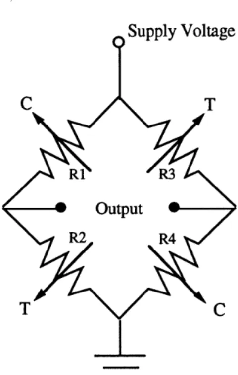
mounted (using M-BondTM adhesive) on both faces of each of the sensor's two beams. With this arrangement, when forces or moments are applied to the end of a beam, one pair of gages experience tension and the other two are under compression (see right hand side of Figure 4-12). Strain gages experience a change in resistance proportional to micro-changes in their length (strain). In basic applications, such as measurement of forces and moments in the beam, it is general practice to mount two pairs of gages "back to back" in this manner, wiring them together to form a Wheatstone bridge circuit as shown in Figure 4-13.
Sunnlv Voltage
Figure 4-13: Strain gage bridge circuit (T=tension; C=compression)
Each arm of the bridge circuit behaves as a voltage divider, and the output is the measured difference between the two dividers. The Wheatstone bridge is desirable because it compares ratios (the outputs of the two dividers) and is thus insensitive to supply changes (Horowitz and Hill, 1989) and common noise. In addition, the full bridge allows for even temperature distribution and compensation in the set of four gages. Output voltage relates simply to input voltage according to the following equation, which again draws from the fact that Vout compares the output voltage of two divider circuits.
R3+ R4 R + R2
-out=I R +R2 /Vi~ (4-9)
Each gage used for this particular application is rated to have a base resistance at zero strain of 5kQ and experiences a change in resistance such that the ratio of that change to
the base resistance is proportional to the strain by its "gage factor"--a MicroMeasurements specification (in this case the gage factor is approximately 2).
Both bridge circuits were powered from an alkaline DC battery supply, and the outputs were separately balanced, filtered and amplified. Early testing of the sensor was performed with a relatively inexpensive AC to DC power supply common to the potentiometer circuits. Unfortunately, power supplies can suffer microvolt changes across reference ground due, for instance, to the capacitive effects of ground loops. This fact became evident in the amplified sensor signal, which was sensitive to these changes in reference ground, despite the bridge circuit configuration. For this reason, bridge supply was provided instead by 9 volt alkaline batteries, configured to provide +9V/Gnd/-9V for instrumentation amplifier supply and with ++9V/Gnd/-9V regulated to +5V for constant bridge supply. This configuration produced an isolated common ground for the sensor circuitry. Additionally, bridge balances were added to zero the output difference before amplification. By having zeroed the bridge outputs, only the changes in strain were recorded and amplified. This is important to the design, since the gages are often individually pre-strained after mounting (varying in resistance from one gage to another), and the bridge can conceivably produce a non-zero output under no load conditions. Amplification of the microvolt outputs of the Wheatstone bridges was performed by Burr-BrownTM instrumentation amplifiers, which provided both a gain of 1000 and common mode noise rejection. But, in spite of the latter, it was still necessary to low-pass filter the high frequency noise remaining in the amplified output signals of the sensor. The basic diagram of the circuit components for an individual bridge is shown in Figure 4-14. Based again upon preliminary testing, frequency spectrum analysis and a known range of waveform frequencies that would have to be measured, the cutoff frequency of the RC-filters was set at 150 Hz.
+ 9V ALKALINE T ND BATTERIES [ ~T-
9
POWER SUPPLY 1-9V 5 k 5 kQf BALANCE BRIDGE - .. A A A-I. xIJ}ULT VxJLar6% . V V V 200 kQFigure 4-14: (a) Power supply, (b)
uutput voltage
7500 pf
RC FILTER
bridge balance, and (c) RC filter.
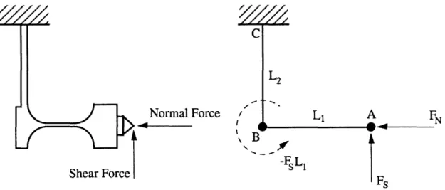
The force sensor was calibrated by applying a series of known forces to the endpoint and measuring the corresponding voltage changes in the bridges. The first basic step in this process was to define the endpoint for which to generate calibration constants. The sensor shape was simplified into a structure like the one shown in Figure 4-15. The
42 +5 Volts
GND
measured forces at the endpoint are shown along with the moment created on beam BC by a shear force at A. C Normal Force .4 - 4 LFN l 1 0 t 4__ N -FsL1 I rs Figure 4-15: Force and moment depiction on the 2-axis force sensor.
Assuming that deflections due to loading are small, and that the joint between the two beams is a sufficiently rigid connection, a simple force balance can be applied to the sensor. It is assumed for this calibration that the resultant force produced by the finger will always be in the center of the indentor, along the axis shown. This condition can be met in the experimental protocol in the way the indentor and finger are lined up with respect to each other. Similarly, if the length of the indentors is constrained, L1 can be kept constant as well. Under these specifications, a normal force, FN, (according to the drawing) will produce bending in Beam 2. A shear force, FS, will produce bending in both beams, due to the force at point A and the bending moment it creates at point B. Strains in a beam experiencing bending are proportional to both forces and moments according to basic beam theory. In fact, if a section of the beam subjected to bending is cut away, strain at a particular location can given by:
£ -MbY (4-10) v7EI, 1 Z X Mb Neutral Axis
Figure 4-16: Beam under bending conditions (not pure bending).
In equation (4-9), £Ex is strain, Mb is moment, y is the distance from the neutral axis, E is Young's Modulus of the material, and Izz is the moment of inertia of the beam. For each beam and its strain gages, all but Mb are constants. The forces applied perpendicular to the neutral axis of the beam produce bending moments at each cross-section in the beam equal to the force multiplied by the distance from point. Therefore, after picking points B and C as calibration points, the bridge output from each beam can be assumed to be functions of the forces applied at the endpoint. A normal force will produce bending in Beam 1, while a shear force will produce bending in both Beam 1 and Beam 2. The preceding relationships come from the facts that (1) strain is proportional to the moments in the beam and (2) voltage output of the bridges is, in turn, proportional to those strains. Because the four gages in a bridge are all equidistant from the neutral axis and are assumed to be well-aligned at the same axial location along the beam, the strains they experience should be equal in magnitude. Only the signs vary between the pair in tension and the pair in compression. Working this relationship of resistance change
corresponding to a given strain experienced by the set of gages in a bridge into equation (4-9) produces
R2 +AR R4 -AR
R-AR+R2 + ARR 3+ R + R R Vi (4-10)
which, since Rl=R2=R3=R4=5kf (base resistance) further reduces to the following
v = R V (4-11)
As stated previously, the resistance ratio is proportional to strain which is, in turn, proportional to the moments in the beam at the bridge location. Combining all of this information, bridge outputs are related to the endpoint forces according to the following equations.
V = ka(FLl) (4-12)
V2 = kb(FNL2)- kc(FsLl) (4-13)
The constants of proportionality (ka, kb, and kc) are the calibration constants of the sensor for the particular point A where loads are applied.
By applying a variety of forces using the weights, calibration constants were determined and checked, and the true accuracy of the sensor was determined for forces at a point A, defined by L1 = 27.45 mm and L2 = 24 mm. The constants used for force
measurement were ka = 50.5 A/D board counts / (mm * Newtons), kb = 15, kc = 17.25. Using this method of calibration, though, the calibration constants are truly accurate only
in predicting loads at the same point. The drawing of the force sensor in Figure 4-16 also indicates that Beam 1 is thinner than Beam 2. With this feature, Beam 1 experiences more strain for the same force (since the moment of inertia of the beam is significantly decreased). Accordingly, measurement of shear force is much finer than that of normal force, in keeping with the design constraints outlined in Section 3.2. The safe range of normal force is on the order of ±3.5 N and ±1.0 N for shear force. This "safe range" is limited by the electronics (5 volt input limits on the A/D channels) and the yield stress limits of the aluminum beams, where elastic deformation gives way to plastic. Plastic deformation in the beams should be avoided since it affects material properties of the aluminum and seriously degrades the performance and resolution of the sensor. The accuracies of the two axes of force, based upon electrical noise and counts resolution are
0.005 N and 0.001 N, respectively. It is important to state again that the constants and
measurements of resolution and accuracy are for loads at the particular point A at which the sensor was actually calibrated. Therefore, it was important to constrain the dimensions of the separate indentors such that both LI and L2, as described in the figure,
were held constant.
In addition to calibrating force vs. voltage output of the sensor, it was necessary for position accuracy of indentation stimuli to determine deflections in the beam as a function of normal force. The measurement of the stimulator joint angles and the kinematics transformation to Cartesian coordinates can determine the position of a fixed endpoint on the stimulator with high accuracy (20-50 microns), based upon a few assumptions. The most important to consider is that bending in the stimulator links and play in the bearings is well below the accuracy limits (i.e. that the structure is "rigid" and changes only orientation, not shape). For the forces imposed on the endpoint, bending in the links is negligible. Similarly, play in the bearings is within the proposed accuracy. However, the force sensor design is based upon the principle of measuring strains 46