HAL Id: hal-02537355
https://hal.archives-ouvertes.fr/hal-02537355
Submitted on 8 Apr 2020HAL is a multi-disciplinary open access archive for the deposit and dissemination of sci-entific research documents, whether they are pub-lished or not. The documents may come from teaching and research institutions in France or abroad, or from public or private research centers.
L’archive ouverte pluridisciplinaire HAL, est destinée au dépôt et à la diffusion de documents scientifiques de niveau recherche, publiés ou non, émanant des établissements d’enseignement et de recherche français ou étrangers, des laboratoires publics ou privés.
Synthesis of Half Fuel Cell Ni-YSZ / YSZ on Porous
Metallic Support by Dry Surface Deposition Processes
Jérémie Fondard, Pierre Bertrand, Alain Billard, Stefan Skrabs, Thomas
Franco, Ghislaine Bertrand, Pascal Briois
To cite this version:
Jérémie Fondard, Pierre Bertrand, Alain Billard, Stefan Skrabs, Thomas Franco, et al.. Synthesis of Half Fuel Cell Ni-YSZ / YSZ on Porous Metallic Support by Dry Surface Deposition Processes. ECS Transactions, Electrochemical Society, Inc., 2013, 57 (1), pp.673-682. �10.1149/05701.0673ecst�. �hal-02537355�
OATAO is an open access repository that collects the work of Toulouse researchers and makes it freely available over the web where possible
This is an author’s version published in: http://oatao.univ-toulouse.fr/24444
Official URL: https://doi.org/10.1149/05701.0673ecst
Any correspondence concerning this service should be sent
to the repository administrator: tech-oatao@listes-diff.inp-toulouse.fr
To cite this version:
Fondard, Jérémie and Bertrand, Pierre and Billard, Alain and Skrabs, Stefan and Franco, Thomas and Bertrand, Ghislaine and Briois, Pascal Synthesis of Half
Fuel Cell Ni-YSZ / YSZ on Porous Metallic Support by Dry Surface Deposition Processes. (2013) ECS Transactions, 57 (1). 673-682. ISSN 1938-5862
10.1149/05701.0673ecst
Synthesis Of Half Fuel Cell Ni-YSZ / YSZ On Porous Metallic Support By Dry Surface Deposition Processes
J. Fondarda,b, P. Bertranda, A. Billarda,b,c, S. Skrabsd, Th. Francod, G. Bertrande , and P. Brioisa,b
a
IRTES-LERMPS, UTBM, 90010 Belfort, France
b
FR FCLab 3539, 90000 Belfort, France
c
LRC CEA, UTBM, 90010 Belfort, France
d
PLANSEE SE, 6600 Reutte, Austria
e
CIRIMAT 5085, ENSIACET, 4 allée E. Monso, BP 44362, 31030 Toulouse Cedex 4, France
A new cell design with metallic porous support was selected in order to face with the reduction of IT-SOFC’s operation temperature. Nevertheless, the excessive roughness of the porous metallic interconnect induce additional problems when a thin electrolyte layer is required. In this work, an anode material (NiO-TSZ) by Atmospheric Plasma Spraying was deposited on metallic supports (ITM) produced by PLANSEE able to cover the roughness of the support. Then, a second thin and dense electrolyte layer (YSZ) by reactive magnetron sputtering was produced on the anode material. In this study, for both processing routes, the optimal process parameters regarding the structural, morphological and electrical characterizations were investigated.
Introduction
The industrialization of solid oxide fuel cells passes through a releasing of several technological obstacles, the main ones are the reduction of manufacturing costs and the increasing of life times. The considered solution to perform this challenge consists in the reduction of SOFCs operating temperature from 1273 to 973 K without deterioration of their performances and with their improvement if possible. This electrochemical device being strongly dependent on the temperature, the lowering of operating temperature leads to a drop in performances. At the level of the core of the cell, two different ways could permit to fulfill these costs reductions and performances gain wishes. The elaboration of the anode/electrolyte/cathode building with thin layers (1) and/or the utilization of innovative materials (2-3) are viable solutions. Moreover, the switch between anode supported cells and the porous metallic support technology (last generation cells) allows significant gains in term of costs thanks to a mechanical support brought by the metal piece and not by the functional materials ceramics (4). The use of this porous support presents some drawbacks. Thermomechanical and chemical compatibility problems between metallic and ceramic materials need to be solved, in particular by avoiding a too strong oxidation of the support which could cause the closing of its porosity (5). Therefore, it is necessary to use elaboration techniques of ceramics with no requirement of heat treatment at too high temperatures. Because of these constraints, industrially applicable dry deposition techniques are a credible solution for the manufacturing of the
heart of the cell. The thermal spray under atmospheric conditions technique (APS) allows the realization of porous layers with very high deposition rate. This technique is perfectly adapted for the anode deposition on the porous substrate (6). The reactive magnetron sputtering technique allows the deposition of thin layers being able to be used as electrolyte layer in fuel cells (7).
For this study, an ITM type porous metallic support manufactured by PLANSEE SE was employed for the half-cell assembling. This material presents very interesting thermal cycling resistance and durability properties keeping high electrochemical properties. Firstly, a NiO-TSZ anode coating is made by APS. In addition, in order to realize the requirements of IT-SOFC’s anodes, the latter need to be able to cover the porous support porosity in order to deposit a gastight electrolyte in the form of thin layer (nearly 10 µ m). Then, an YSZ electrolyte layer is deposited by reactive magnetron sputtering with a closed loop control system (8). The structural, microstructural and morphological features were determined by XRD, SEM and 3D profilometry. Finally, the electrical properties of the films were obtained by four points probe measurements and Electrochemical Impedance Spectroscopy (EIS) in function of temperature.
Experiments
Plasma Sprayed Process
The plasma was generated in air at atmospheric pressure (APS) by a F4 plasma torch with a 6 mm internal nozzle diameter. A mixture of argon and hydrogen was used to form the plasma. The powder was injected by the means of carrier gas. It was introduced into the plasma via a 1.8 mm injector positioned at 6 mm from the exit of the outlet of the torch with a 90° angle. Samples were positioned on a fixed support at a distance of 90 mm from the plasma torch. The torch was controlled by a robot programmed to sweep samples surface with a step of 5 mm at a speed of 150 mm/s. Deposits were made of 10 passes in order to have a desired thickness.
Reactive Magnetron Sputtering Process
The experimental device was a 100-litre Alcatel SCM 650 sputtering chamber pumped down via a system combining XDS35i Dry Pump and a 5401CP turbo-molecular pump. The sputtering chamber was equipped with three 200 mm diameter magnetron targets and with a 620 mm diameter rotating substrate holder parallel to the targets at a distance of about 110 mm. The distance between the targets axis and that of the substrate holder was 170 mm. A Zr-Y metallic target (84-16% at) was powered by a pinnacle + pulsed current generator from Advanced Energy. Substrates were positionned in front of the target at 170 mm from the axis of the rotative substrate holder in order to deposit homogenous coatings in terms of thickness and composition. Tests were conducted in an argon and oxygen atmosphere. The flow rates were controlled with Brooks flowmeters and the pressure was measured using a MKS Baratron gauge. The deposition stage was monitored using a closed loop control PEM (Plasma Emission Monitoring) system by means of the optical emission spectroscopy (OES) (8). The technique was based on the measurement of the optical intensity of the Zr emission line ( ) in a volume near the
target. The signal was sent via an optical fiber to a Ropper Scientific SpectraPro 500i spectrometer, with a 1200 groove mm−2 grating and a photomultiplier tube (Hamamatsu R 636). Subsequently, the information was transferred to a computer in which a program developed under Labview® controls the oxygen flow rate for keeping optical intensity constant.
Characterization Devices
The morphology of the coatings/powders was characterized by Scanning Electron Microscopy (SEM) using a JEOL JSM 7800 F equipped with Energy Dispersive Spectroscopy (EDS) for chemical measurements. The structural features of the supports and coatings were performed in Bragg Brentano configuration X-ray diffraction using a BRUKER D8 focus diffractometer (CoKα1+α2 radiations) equipped with the LynxEye linear detector. XRD patterns were collected at room temperature during 10 min in the [20°-80°] scattering angle range by steps of 0.019°. Samples roughnesses were measured by an Altisurf profilometer by the means of an optical sensor without contact. This measure is conducted at a distance of 17.5 mm with 10 measures line by line. Surface condition of samples is built by a 1 mm² measurement after the signal filtration and the ondulation component removal. The size of powders is determined by a Mastersizer 2000 laser granulometer by dry way. The optical transmittance measurements were performed with a UV-visible-NIR Shimadzu UV-3600 Spectrophotometer control by UV probe 2.33 software. All measurements were carried out on glass slide to 380 – 780 nm wavelengths. The electrical resistivity measurements were performed with HP 3458A multimeter on the Ni-YSZ film deposited on porous metal support substrates. The four-point-probe technique with four Pt aligned electrodes was employed. Two outer probes are the current-carrying electrodes (I1, I2) and the two inner ones were used for measuring the voltage (E1, E2). Resistivity measurements are made at room temperature by the means of a Jandel device certified for allowing the determination of the form factor of the temperature measured cell. Electrochemical measurements were done on Ni-YSZ/YSZ half-cells under 60 sccm nitrogen by the means of a Solartron SI 1260 impedance / gain analyser from 20 MHz to 0.1 Hz with 11 points per decade.
Results
Characterization of the Porous Metallic Support
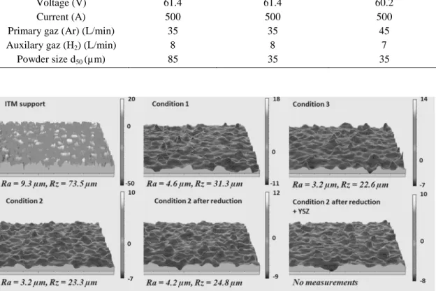
ITM porous metallic supports with a 1 mm thickness present 40% porosity. The diameter of these porosities is ranging from 20 to 60 µ m. The parameter characteristic of the distance (Ra) in the average roughness profile line is near 9 µ m while the distance between the deepest valleys and the highest peaks is around 75 µ m (figure 1). These values confirmed the strong roughness of the sample.
Elaboration of the Anode Layer by APS
Thermal spraying elaboration conditions are shown in Table I. The anode layer must provide good mechanical strength and fill the large pores in the substrate that are between
TABLE I. Thermal Spray Deposition Conditions
Parameters Condition 1 Condition 2 Condition 3 Feedstock NiO-TSZ powder (58-42 % wt)
Voltage (V) 61.4 61.4 60.2
Current (A) 500 500 500
Primary gaz (Ar) (L/min) 35 35 45
Auxilary gaz (H2) (L/min) 8 8 7
Powder size d50 (µ m) 85 35 35
Figure 1. Surface condition and roughness of samples by profilometry measurements.
Figure 2. NiO-TSZ powder granulometry.
20 and 60 microns. The pore size of the substrate extending over a wide range, two sizes of dry-agglomerated but not consolidated powders were used for the synthesis of coatings (figure 2). Therefore, a NiO-TZP powder (58-42 % wt) was chosen with a tetragonal zirconia thanks to its better mechanical properties than cubic zirconia (figure 3). Figure 1 shows that the realization of the APS anode layer reduces the roughness of the substrate. In addition, an increasing the hydrogen flow rate (for the same powder size) allows a better melting of the powder in the plasma leading to obtain a lower Ra (smoother surface).
TABLE II. Composition of Different Samples Atomic % Ni Zr Y O % vol Ni powder 30.66 12.47 0.54 56.32 55.9 Condition 1 21.62 ± 0.38 18.11 ± 0.36 1.16 ± 0.02 59.11 ± 0.10 35.8 Condition 1 reduced 27.93 ± 0.37 21.19 ± 0.04 1.35 ± 0.02 49.53 ± 0.37 25.4 Condition 2 21.00 ± 0.35 18.64 ± 0.28 1.20 ± 0.04 59.16 ± 0.04 35.5 Condition 2 reduced 28.01 ± 0.45 21.23 ± 0.16 1.34 ± 0.02 49.42 ± 0.33 25.4 Condition 3 20.20 ± 0.57 16.25 ± 0.20 0.97 ± 0.01 62.58 ± 0.36 38.1 Condition 3 reduced 31.27 ± 0.59 19.54 ± 0.27 1.16 ± 0.10 48.04 ± 0.22 29.3
Figure 3. XRD measurements of NiO-TSZ powder, as-deposited, reduced samples and half cell. In te n sit y ( a rb . U n it ) 2 Ө (°)
The composition analyses determined by EDS (shown in Table II) did not allow to find a significant influences regarding the preparation conditions. The Ni content in the film decreases as compared with that of starting powder. This behavior is imputed to the high proportion of hydrogen in the plasma, which leads to a reduction of NiO to Ni and causes its volatilization (9). This phenomenon is confirmed by the analysis of the structure of coatings by XRD where NiO and Ni phases were clearly detected. NiO reduced rate is higher in the samples deposited with a higher proportion of hydrogen in the plasma (figure 3). The structure analysis of the coatings allowed to identifiy the presence of an additional phase constituting the shoulder peak TSZ (figure 3). Analysis of JCPDS datas did not allow to attribute all the phases accurately. This fact, could be ascribed to a TSZ phase with a different lattice parameter as an incorporation of Ni in its structure is believed to take place.
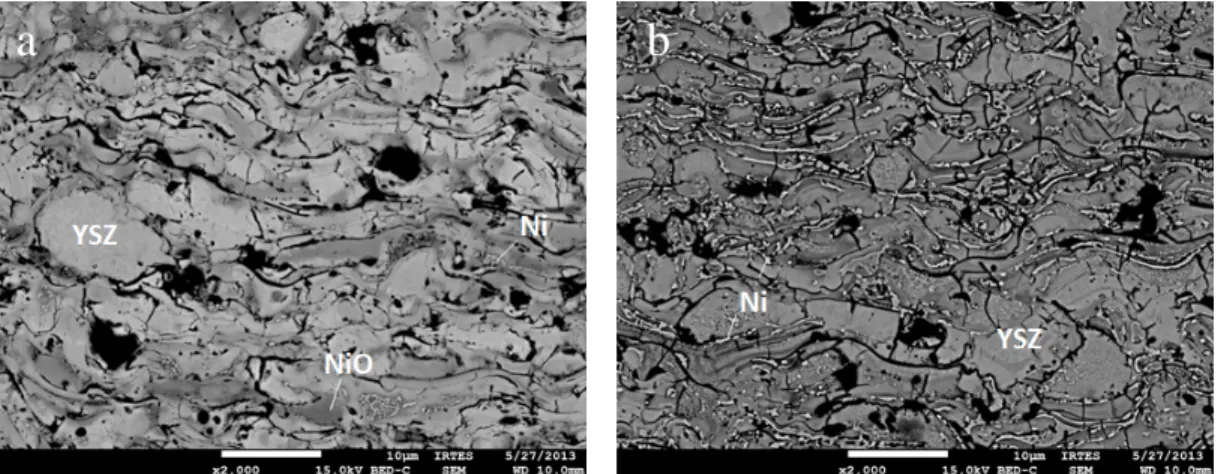
Figure 4. Microstructure of anode coatings deposited in the operating condition 2 as-deposited (a) and after reduction under 90 Ar / 10 H2 mixture at 773 K for 3h (b).
Figure 5 presents the electronic conductivity of the sample prepared in the operating condition 2 and then reduced, measured by the four points probe method from 293 to 1173 K. The conductivity of the sample at the IT-SOFC operating temperatures is about 10 S/cm at 973 K, this value is relatively low for the employment as an anode in IT-SOFC (minimum 100 S/cm) due to the low rate of Ni (≈ 25 vol %).
Figure 5. Conductivity of reduced anode deposited in the operating condition 2.
a
b
SEM observations on the BSE mode of the coating deposited by condition 2 morphology before and after reduction in an Ar (90 sccm) - H2 (10 sccm) mixture at 773
K for 3h is presented in figure 4. Analyses of these micrographs confirmed the presence of NiO and YSZ phases in addition to few quantities of metallic Ni in the form of thin strips. It should be noted that the porosity of the coatings is about 12% for the as-deposited film and 15% for the reduced sample. In fact, the NiO initially present in the powder is believed to be strongly reduced in the anode. The porosity was calculated by averaging over 20 photos by image analysis from the ImageJ software. XRD analysis of the reduced sample exhibited only the presence of metallic Ni highlighting the reduction of the anode (figure 3). In addition, this treatment did not significantly deteriorate the roughness of the anode (figure 2).
Elaboration of the Electrolyte Layer by Reactive Magnetron Sputtering
These coatings were made from a metallic ZrN target (84/16 at %). Table III sunnnarizes the preparation conditions of the electrolyte. The objective is to obtain a dense and high temperature resistant coating in the view of the cathode elaboration. Samples were deposited on glass slides and on commercial Niü-YSZ anodes produced by Jülich. Sputtering a metal target in an argon-oxygen plasma generally leads to a sputtering instability regime phenomenon with a low deposition rate to obtain ceramic film. To li.mit this behavior, control of oxygen levels in the room via closed loop control was employed in order to contrnl the optimum deposition rates (10).
TABLE III. Magnetron Sputtering Deposition Conditions
Draw distance (mm) 110 Cun-ent applied on target (A) 2.5 Ar flow rate (sccm) 25 Setpoint (%) 15-35 Deposition rate (µm/h) 0.4-0.9
The analysis of the optical transmission of coatings (figure 6) allowed defining if the film is transparent or absorbing. An absorbent coating (setpoint 35% in figure 6) presents few oxygen while a non-absorbent coating is oxygen saturated (setpoint 15% in Figure 6). Samples were then annealed at 973 K for 2 h in order to saturate the coating in oxygen and also to allow it having an increase of volume which improves the densification (11 ).
Figure 6 shows the surface m01phology of the samples after annealing at 1523 K for 2 h.
The coating made with a setpoint of 20% presented large cracks while the one deposited at 35% did not exhibited the same m01phology. The annealing at 1523 K causing severe constraints in coatings. 100 l glass 90 -y---;�---=----�---::-� ro 70 " 30 20 10 35% 0 ---==:;:::==:::;::::::==::===:;:::==:::;::::::==::===:;:::= -380 430 480 530 580 630 680 730 780 Wavelength (nm)
Figure 6. Optical transmission and SEM to surface micrographs of samples deposited with different setpoints.
Ni-YSZNSZ Half-cell Analyses
Samples (ITM/Ni-YSZNSZ) were oxidized at 923 K for 2 h and then reduced in the
same conditions. They were analyzed by means of X-ray diffraction (figure 3) exhibiting
Figure 7. XRD measurements of half-cell sample after mechanical polishing with 10 µm steps from the surface to the interface with the metal support.
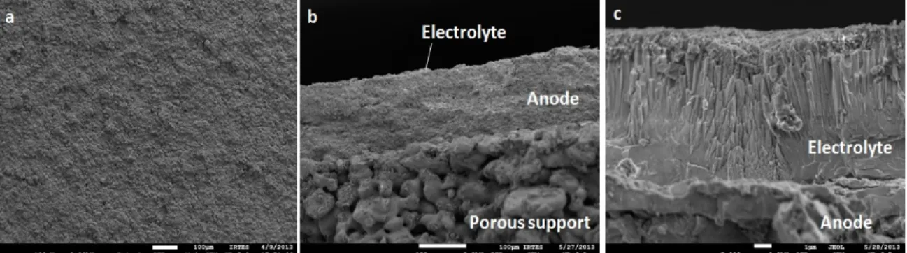
Figure 8. Micrography of half-cell elaborated in the operating condition 2. top view (a); fracture of the half-cell (b, c).
behavior is ascribed to the electrolyte thickness which was about 11µm. The response of the anode and the porous support are not clearly visible (figure 3). The structure of a half cell sample was analyzed by XRD after mechanical polishing with 10 microns steps from the surface of the coating to the interface with the metal support (figure 7).
Ni, YSZ and un-oxidized ITM were only observed (figure 7), reflecting the effectiveness of the reduction treatment of the stack. Figure 8 showed the surface (figure 8a) and half-cell rupture (Figure 8b and c) observation. In spite of the disturbed surface condition, electrolyte coating was covering the entire surface (Figure 8a). The different layers were adherent (Figure 8b, c), anode and electrolyte layers thicknesses were 95 and 11 µ m, respectively. The electrolyte coating presented a columnar morphology caused by the surface of the anode after annealing and reduction (Figure 8c). This behavior had been already described on commercial anodes (7).
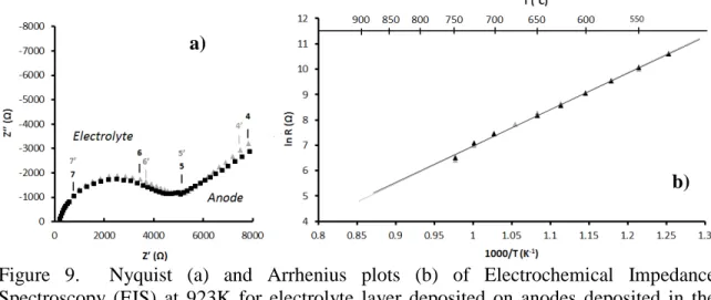
Figure 9. Nyquist (a) and Arrhenius plots (b) of Electrochemical Impedance Spectroscopy (EIS) at 923K for electrolyte layer deposited on anodes deposited in the operating conditions 1 and 2.
Polarization resistances of the anodes are very important. The emploted values are comparable to those made in the literature on a half-cell NiO-GDC/GDC (12). Analysis by X-ray diffraction of samples after the test effectively indicates anode and porous metal support oxidation. A test was performed under the same conditions on the metal support alone with a sweeping of the sample under nitrogen for 2 hours before measurements. The resistance of this sample was reduced, which means that if was oxidized during the test. Regarding these results, it is necessary to perform electrochemical tests of the half cells after sweeping 2 h under N2 in order to ensure the absence of oxygen in the
deposition chamber, or to work in a reducing environment. However, electrolyte resistance measurements (figure 9b) allowed to define the activation energy which was about 1.2 eV, being slightly higher than the literature (7, 13).
Conclusion
The different layers were deposited on the surface of the ITM porous metal supports provided by Plansee by the means of dry deposition techniques. The anode layer was deposited on the porous support by plasma spraying in atmospheric conditions. This technique allowed covering the surface porosity and limiting the half-cell roughness. Structure of the powder was modified during the deposition. On one hand nickel was reduced during the deposition of the powder in the plasma which created coatings with few porosity even after reduction. On the other hand, the elaboration condition 2 is the one that provided the best results since the initial roughness was reduced in a half order. The electrical conductivity of the samples was evaluated by four points probe measurements. In the IT-SOFC operating temperature, the conductivity was below the
a)
b)
Figure 8 showed the Nyquist diagram (Fig. 9a) and the Arrhenius plot (Figure 9b) of the half-cell with an anode produced by condition 1 or 2. Measurements were performed from 773 to 1173K under 60 sccm of nitrogen in order to prevent the anode and porous oxidation support. The response of the half-cell was imputed to three R-CPE elements in series. The first element corresponded to electrolyte response at high frequency (10 MHz). The other two were assigned to anode response at medium frequency (1 kHz) and low frequency (10 Hz).
1. E. Ivers-Tifée, A. Weber, D. Herbstritt, Journal of the European Ceramic Society,
21, 1805 (2001).
2. J.B. Goodenough, Y-H. Huang, Journal of Power Sources, 173, 1 (2007).
3. J. Molenda, K. Swierczek, W. Zajac, Journal of Power Sources, 173, 657 (2007). 4. M.C; Tucker, Journal of Power Sources, 195, 4570 (2010).
5. M. Brandner, M. Bram, J. Froitzheim, H.P. Buchkremer, D. Stöver, Solid State Ionics, 179, 1501 (2008).
6. R. Vaβen, D. Hatiramani, J. Mertens, V.A.C. Haanappel, I.C. Vinke, Surface and Coatings Technology, 202, 499 (2007).
7. P. Briois, A. Billard, Surface and Coatings Technology, 201, 1328 (2006). 8. F. Perry, A. Billard, C. Frantz, Surface Coatings Technology 94-95 681 (1997). 9. M. Poon, O. Kesler, Journal of Power Sources, 210, 204 (2012).
10. P. Briois, L. Yu, M. Arab Pour Yazdi, S. Georges, A. Billard, Proceedings of SOFC XIII conference (2013).
11. P. Briois, C. Mazataud, S. Fourcade, F. Mauvy, J-C. Grenier, A. Billard, Journal of the Electrochemical Society, 35, 1275 (2011)
12. M.G. Chourashiya, L.D. Jadhav, International Journal of Hydrogen Energy, 36, 14984 (2011).
13. H. Wang, W. Ji, L. Zhang, Y. Gong, B. Xie, Y. Jiang, Y. Song, Solid State Ionics,
192, 413 (2011).
required minimum because of the few proportion of nickel in the coating. The electrolyte was deposited by reactive magnetron sputtering. This technique allows depositing a layer that accommodates the surface defects of the anode. This coating is also resistant to annealing performed at very high temperatures. Half-cells were successfully built by the means of two different dry deposition techniques with very good adhesion and interesting microstructures. They were then tested by electrochemical impedance measurements under nitrogen flow. Resistance measurements of the anode were abnormally high, and are certainly due to the presence of NiO phase in the anode during the test. After impedance measurements, anode layer and porous support were partially oxidized. Measurements on the electrolyte were used to determine the activation energy of 1.2 eV which is higher than the value of 1.0 eV found in the literature. As a future activity, electrochemical measurements in a reducing environment are envisaged with the aim of getting rid of the oxidation of the anode. Finally, it would be interesting to refine structural analysis of cells by means of Raman spectroscopy.
Acknowledgments
This study was granted by the Pays de Montbéliard Agglomeration. Authors acknowledge Plansee by their contribution of the porous metal support employed in this study.