Publisher’s version / Version de l'éditeur:
Vous avez des questions? Nous pouvons vous aider. Pour communiquer directement avec un auteur, consultez la
première page de la revue dans laquelle son article a été publié afin de trouver ses coordonnées. Si vous n’arrivez pas à les repérer, communiquez avec nous à [email protected].
Questions? Contact the NRC Publications Archive team at
[email protected]. If you wish to email the authors directly, please see the first page of the publication for their contact information.
https://publications-cnrc.canada.ca/fra/droits
L’accès à ce site Web et l’utilisation de son contenu sont assujettis aux conditions présentées dans le site LISEZ CES CONDITIONS ATTENTIVEMENT AVANT D’UTILISER CE SITE WEB.
Student Report; no. sr-2009-21, 2009-01-01
READ THESE TERMS AND CONDITIONS CAREFULLY BEFORE USING THIS WEBSITE. https://nrc-publications.canada.ca/eng/copyright
NRC Publications Archive Record / Notice des Archives des publications du CNRC :
https://nrc-publications.canada.ca/eng/view/object/?id=77962add-5bf6-4c9e-bda1-caeb48ec0765 https://publications-cnrc.canada.ca/fra/voir/objet/?id=77962add-5bf6-4c9e-bda1-caeb48ec0765
NRC Publications Archive
Archives des publications du CNRC
For the publisher’s version, please access the DOI link below./ Pour consulter la version de l’éditeur, utilisez le lien DOI ci-dessous.
https://doi.org/10.4224/18253435
Access and use of this website and the material on it are subject to the Terms and Conditions set forth at Communication Interface Development of the Ice Hull Interaction (IHI) Bridge Version
National Research Council Canada Institute for Ocean Technology Conseil national de recherches Canada Institut des technologies oc ´eaniques
SR-2009-21
Student Report
Communication Interface Development of the Ice Hull
Interaction (IHI) Bridge Version.
Zhao, F.; Lau, M.
Zhao, F.; Lau, M., 2009. Communication Interface Development of the Ice Hull Interaction (IHI) Bridge Version. St. John's, NL : NRC Institute for Ocean Technology.
DOCUMENTATION PAGE REPORT NUMBER
SR-2009-21
NRC REPORT NUMBER DATE
December 22, 2009
REPORT SECURITY CLASSIFICATION
Unprotected
DISTRIBUTION
Unlimited
TITLE
Communication Interface Development of the Ice Hull Interaction (IHI) Bridge Version
AUTHOR(S)
Feng Zhao and Michael Lau
CORPORATE AUTHOR(S)/PERFORMING AGENCY(S)
Institute for Ocean Technology
PUBLICATION
SPONSORING AGENCY(S)
Centre for Marine Simulation, Marine Institute
IOT PROJECT NUMBER
PJ2200
NRC FILE NUMBER KEY WORDS
Simulation, IHI, OSIS, Polaris, Integration, Communication interface, Communication protocol, User manual
PAGES 16 FIGS. 10 TABLES 7 SUMMARY
As part of the joint project between the Centre for Marine Simulation (CMS) and the Institute for Ocean Technology (IOT) under PJ2200, this report documents the integration of the Ice Hull Interaction (IHI) module with the Ocean Structure Interaction Simulator (OSIS) and Polaris system. The report also describes the development of the IHI-OSIS and the IHI-Polaris
communication interfaces. A user manual for the communication interface is also given in this report.
ADDRESS: National Research Council
Institute for Ocean Technology Arctic Avenue, P. O. Box 12093 St. John's, NL A1B 3T5
National Research Council Conseil national de recherches Canada Canada
Institute for Ocean Institut des technologies
Technology océaniques
COMMUNICATION INTERFACE DEVELOPMENT OF THE ICE HULL
INTERACTION (IHI) BRIDGE VERSION
SR-2009-21
Feng Zhao and Michael Lau
ACKNOWLEDGEMENT
The investigations presented in this report were partially funded by the Centre for Marine Simulation (CMS) of Marine Institute and the Institute for Ocean Technology (IOT) of National Research Council of Canada. The funding for this work is gratefully
acknowledged.
The first author thanks his supervisor Dr. Michael Lau for his guidance throughout the project. Thanks also due to the supervisor of IOT’s software group, Mr. Mike Sullivan, and our colleagues Dr. Shaoyu Ni and Mr. Wayne Pearson. All their work and support for this project are gratefully acknowledged.
ABSTRACT
As part of the joint project between the Centre for Marine Simulation (CMS) and the Institute for Ocean Technology (IOT) under PJ2200, this report documents the
integration of the Ice Hull Interaction (IHI) module with the Ocean Structure Interaction Simulator (OSIS) and the Polaris system. The report also documents the development of the IHI-OSIS and the IHI-Polaris communication interface. A user manual for the communication interface is given at the end of the report.
SUMMARY
As a part of the joint project between the Center for Marine Simulation (CMS) and the Institute for Ocean Technology (IOT) under PJ2200, this report documents the
integration of the Ice Hull Interaction (IHI) module with the Ocean Structure Interaction Simulator (OSIS) and Polaris system. The report also includes the development of the communication interface of the IHI-OSIS and the IHI-Polaris. A user manual for the communication interface of the IHI bridge version is given at the end of the report. The integration section shows how to use the IHI-OSIS module to develop IHI module and then use that module to integrate into the Polaris system as the final product. The bridge software was developed for the IHI-OSIS and IHI-Polaris system by using different communication protocols. The communication interface will allow the IHI module to communicate with OSIS or Polaris, in order to transmit data through each other. The current version of the bridge software was designed based on the Polaris interconnection application with User Datagram Protocol/Internet Protocol (UDP/IP). It supports the IHI-Polaris simulation system to provide stable, and fast real time based simulation performance. For further application of the IHI module with bridge version, a user manual is given in the appendix.
TABLE OF CONTENTS
ACKNOWLEDGEMENT ... ii
ABSTRACT...iii
SUMMARY ... iv
1.0 INTRODUCTION ... 1
2.0 TECHNICAL AND OPERATIONAL FEASIBILITY ... 3
2.1 EQUIPMENT AND SOFTWARE ...3
2.2 STANDARD DESIGN PROCESS...5
3.0 INTEGRATION ... 6
3.1 IHI-OSIS INTEGRATION ...6
3.2 IHI-POLARIS INTEGRATION...7
4.0 COMMUNICATION INTERFACE DEVELOPMENT... 9
4.1 TCP AND UDP TRANSPORT SERVICES ...9
4.2 IHI-OSIS BRIDGE SOFTWARE...10
4.3 POLARIS INTERCONNECTION ...11
5.0 CONCLUSION ... 16
6.0 REFERENCES ... 16
Appendix A THE USER MANUAL... 17
LIST OF FIGURES
FIGURE 1, KONGSBERG POLARIS SYSTEM... 1
FIGURE 2, OSIS OPERATING WINDOW... 2
FIGURE 3. THE STAGES IN SOFTWARE DEVELOPMENT... 5
FIGURE 4, IHI-OSIS MODEL... 6
FIGURE 5, FLOW CHART OF IHI-OSIS PROGRAM CIRCLE... 7
FIGURE 6, IHI-POLARIS MODULE... 8
FIGURE 7. SERVER/CLIENT NETWORK... 9
FIGURE 8. IHI-OSIS TCP STRUCTURE... 10
FIGURE 9. IHI-OSIS UDP STRUCTURE... 11
FIGURE 10. DATAGRAM STRUCTURE... 13
LIST OF TABLES TABLE 1, IHI COMPUTER SYSTEM SPECIFICATION... 4
TABLE 2, MESSAGES AND PORTS... 12
TABLE 3, NORCONTROL HEADER FORMAT... 12
TABLE 4, RECORD HEADER... 13
TABLE 5. CMS ACTIVE RECORD... 13
TABLE 6. MOVE RECORD FORMAT... 14
COMMUNICATION INTERFACE DEVELOPMENT OF
THE ICE-HULL INTERACTION (IHI) BRIDGE VERSION
1.0INTRODUCTIONAs part of the joint project between the Institute for Ocean Technology (IOT) and the Centre for Marine Simulation (CMS), the Ice-Hull Interaction (IHI) module was developed for inclusion in the Kongsberg’s Polaris system for ship manoeuvring in ice simulation (Figure 1).
Figure 1, Kongsberg Polaris system
The Ocean Structure Interaction Simulator (OSIS) is a simple computer simulation tool designed for showcasing any dynamic interaction system (Figure 2). This program was upgraded to provide a full ship manoeuvring in ice simulation capability by incorporating modules for hydrodynamic, propulsion and ice-hull interaction (IHI) modeling and a sophisticated manoeuvring motion solver. It is designed by IOT in MATLAB
environment, which is able to help in repackaging the IHI module for Full-Bridge
simulator application as well as developing the communication interface between IHI and the Polaris.
Since the Polaris system is not available in IOT, the OSIS-IHI program was used to assist in the communication interface development. The OSIS program was able to do similar simulation as the Polaris system. This allows IOT to go ahead with the communication interface development and try out the IHI module without connecting to the Polaris system. Furthermore, the OSIS-IHI could provide independent validation of force data
transfer. The OSIS-IHI program can be run as stand-alone version, or bridge version with communication interface.
2.0 TECHNICAL AND OPERATIONAL FEASIBILITY
The technical and operational feasibilities of developing a communication interface between IHI and the Polaris were considered at start of this project. Can the objective of this project be achieved with current equipment and existing software support? Does it require new additions? Will the design be used if it is developed and implemented? 2.1 Equipment and Software
• Equipments
There are two basic configurations for the integration, the IHI-OSIS version and the IHI-Polaris version. The IHI-OSIS is able to run as a stand-alone version that requires only a single computer.
With two sessions of MATLAB activated on the same computer, the IHI-OSIS can be tested on a local host. In order to separate IHI and OSIS into two
independent applications for testing on the IOT LAN, two computers and a network switch are needed.
A powerful computer has been ordered by CMS for the IHI-Polaris integration. The IHI module will be installed on this computer for ice force computation. Table 1 shows the hardware specification recommended for the IHI installation. • MATLAB:
OSIS and IHI are developed by IOT in MATLAB environment. In order to run the programs, MATLAB software is required. An executable of the IHI Bridge version will be supplied to CMS so to allow the user to run the software without acquiring the Matlab license.
• Instrument Control Toolbox
The Instrument Control Toolbox is used for the UDP communication protocol implemented in this project. This software is a collection of M-file functions built on the MATLAB technical computing environment. For the application of this project, the toolbox provides a framework for communicating with instruments that support the GPIB interface, the VISA standard, and the TCP/IP, and UDP protocols. The toolbox extends the basic serial port features included with the MATLAB software. The toolbox also has the functions that transferring data between the MATLAB workspace and the instrument in binary (numerical) or text.
For more details of the software or a list of the toolbox functions, type help
• Python
A python application was designed by Mr. Wayne Pearson in order to test the communication interface of the IHI module at IOT prior to its integration with the Polaris system. The software includes a data library, which is the same as the Polaris data format, and it mimics the way Polaris broadcasting and receiving data. For the test of IHI-Polaris program, the Python software is used for listening and sending data to the IHI.
Table 1, IHI computer system specification
Item Model # # of
items Description Motherboard ASUS P6TD Deluxe 1
ASUS P6TD Deluxe LGA 1366 Intel
X58 ATX Intel Motherboard
Chip 1
Intel Core i7 975 Extreme Processor BX80601975 - 3.33GHz, LGA 1366, 6.4GT/s QPI, 8MB L3 Cache, Quad-Core, HyperThreading, Bloomfield Memory (RAM) CMD12GX3M6A1600C8 2 CORSAIR DOMINATOR 12GB (6 x 2GB) 240-Pin DDR3 SDRAM DDR3 1600 (PC3 12800) Storage - SSD/HDD SSDSA2SH032G1 3
Intel X25-E Extreme SSDSA2SH032G1
2.5" 32GB SATA II SLC Internal Solid
state disk (SSD) Video Cards 896-P3-1257-AR 2
EVGA GeForce GTX 260 Core 216 Superclocked Video Card - 896MB GDDR3, PCI Express 2.0
Case HAF 932
RC-932-KKN1-GP 1
COOLER MASTER HAF 932 RC-932-KKN1-GP Black Steel ATX Full Tower Computer Case
Cooling Domino A.L.C 1 CoolIT SYSTEMS Domino A.L.C Advanced Liquid Cooling
Power Supply
XHA4-1200W-135F-BKT 1
Ultra X3 ULT40070 1600-Watt Power
Supply - ATX, SATA-Ready, PCI-E Ready, Energy Efficient, Modular, Lifetime Warranty
Operating
System Windows 7 1
Microsoft Windows 7 Professional 64BIT
2.2 Standard Design Process
A standard development process was followed in order to ensure good quality of the final product. Figure 3 shows the stages in the software development. The developmental process was based on those steps. Research and design were conducted prior to programming of the software.
If new additions are to be introduced in the system
Preliminary Investigation Design Testing Coding Finish Implementation Analysis Start
3.0 INTEGRATION
The Polaris system is not available at IOT. Thus if any test is needed to access the Polaris system, the developer would has to bring the software to CMS with the necessary
hardware and software. Two pieces of software are available at IOT to assist in the development of the IHI-Polaris system. One is the IHI-OSIS program. Instead of using the real IHI-Polaris system, IOT developed the IHI-OSIS model for the simulation and communication interface testing at IOT. Another application (based on Python) was used for the Polaris interconnection test, which was designed by Mr. Wayne Pearson.
3.1 IHI-OSIS Integration
In the IHI-OSIS program, the IHI is an ice force module embedded in OSIS that provides a motion solver for the motion computation. Both IHI and OSIS are running
independently and are able to run on the same physical LAN with the communication interface. OSIS simulates the ship motion in ice, and sends the data to IHI through the network. Then IHI picks up the ship motion data, and provides ice force computation results back to the OSIS. OSIS will generate new ship motion data based on the ice force results received from IHI, and sends the updated motion data back to IHI again. (See Figure 4.)
IHI OSIS
IHI Ice Force
Ship Motion
Figure 4, IHI-OSIS model
The IHI-OSIS system is able to run as a stand-alone version without the communication interface. The main m-file named osisSimulationShipInIce.m allows the programmer to set the IHI-OSIS to run as a stand-alone (without the communication interface) or a bridge (with communication interface) version. The programmer may set the value of the variable server_client equals to 1 that enables the bridge option; or set server_client equals to 0, which forces the program to run as a stand-alone version. The purpose of availing the option of running as stand-alone version is that the results of this version could be used as a reference to check the validity of the bridge version.
For the IHI-OSIS program running with the communication interface, two
communication models were successfully implemented. Each model has been designed with different communication protocols, and the communication protocol development
will be discussed in details in the next section. Disregarding to the type of
communication protocol implemented in the IHI-OSIS, same algorithmic circle is followed. Figure 5 shows a flow chart of the IHI-OSIS’ algorithmic circle.
IHI Start Computation Receive Sending Data Computation Receive Computation Sending Data OSIS Start
Figure 5, Flow chart of IHI-OSIS program circle
In the IHI-OSIS version, it doesn’t matter if IHI starts first or OSIS starts first, since either component reaches the ‘receive’ status, it will hibernate and wait for the data to come until the input from the other side activates the process again.
3.2 IHI-Polaris Integration
After the IHI module had been completely re-packaged and verified with the IHI-OSIS program, it was integrated into the Polaris system as the final product.
There are two possible means to connect IHI to the Polaris system: (1) the SETGET software provided by Kongsberg for data passing between Polaris and external
applications and (2) the Polaris’ existing interconnection facility. Currently, the SETGET software does not allow passing of external forces, and its usage for data passing is not
clear with the associated documentation lacking. Furthermore, since the Polaris’ interconnection facility has been set up to provide successful and well defined mean of data transfer, this option was selected for implementation. In order to integrate with Polaris by its interconnection, the IHI module was upgraded to match the Polaris interconnection requirements.
The IHI-Polaris is similar to IHI-OSIS in many ways, but with one significant difference. According to CMS, Polaris can only accept environment data such as current velocity. It uses these current data to compute current load on the ship. The only way to pass IHI ice force to the Polaris is to convert IHI ice forced to a set of ‘equivalent’ currents that in turn are used by Polaris to compute an ‘equivalent’ current load on the ship to mimic external ice force. Hence, in the IHI-Polaris version IHI computes ice force using the motion data passed from Polaris, and the ice force is then converted to current velocity and passed back to the Polaris with a pre-set format of current message that it can accept (Figure 6).
4.0 COMMUNICATION INTERFACE DEVELOPMENT
Both IHI-OSIS and IHI-Polaris communicate through a Server/Client networking system (Figure 7). Two types of protocols are used in both systems: Transmission Control Protocol/Internet Protocol (TCP/IP), and User Datagram Protocol/Internet Protocol (UDP/IP).
Communication
Channel
Computer#2:
CLIENT
Computer#1:
SERVER
Figure 7. Server/Client Network
OSIS plays the role of server in the IHI-OSIS system, and Polaris replaces OSIS as the server for the IHI-Polaris system. The IHI is always the client in the networking system. The server and client communicate with each other through the communication channel configured according to standard protocol.
4.1 TCP and UDP Transport Services
Both the TCP and UDP protocols use the connectionless packet network service provided by IP. TCP provides for reliable transfer of byte streams between processes activated in hosts, which are connected to the Internet. The processes write bytes into a buffer for transfer across the Internet by TCP. TCP is considerably more complex than UDP. TCP involves the establishment of a connection between the two processes, whereas, UDP provides port numbering to identify the source and destination processes activated in each host. UDP is simple and fast but provides no guarantees in terms of delivery or sequence addressing (Leon-Garcia and Widjaja, 2003).
To provide the service, TCP entities implement error detection and retransmission as well as flow control algorithms. For example, when an error occurs during the transmission, the data will be retransmitted to guarantee all data are successfully delivered. This may cause a time lagging problem, especially for time based communication applications. UDP is used for applications that require quick but not necessarily reliable delivery. The UDP client attaches a header to the user information to provide port information and encapsulates the resulting block in an IP packet. Contrary to the TCP, there is no
requirement to set up hand-shaking dialogues and the datagram can be sent immediately. The UDP protocol is commonly used for simulator communication. Since the IHI-Polaris system requires real time simulation and the Polaris broadcasting the data every tens of
millisecond, the current design for the IHI-Polaris communication software uses the UDP protocol.
4.2 IHI-OSIS Bridge Software
The bridge version of IHI-OSIS runs with the communication interface. Both TCP and UDP protocols were designed for this version.
The TCP version of the IHI-OSIS bridge software was written in MATLAB environment with embedded Java classes. The Java.io and java.net packages were used for the TCP communication interface with the software opens two ports for data transmission. When OSIS sends ship motion to IHI, the data is sent through port 3000; and another port is opened for the data ID in order to ensure the receiving end could get all the data in the correct order. Figure 8 shows the TCP communication structure of the IHI-OSIS program. ID Data MSG size Result
Client
(IHI)
Server
(OSIS)
Figure 8. IHI-OSIS TCP structure.
In order to keep both the server and client running in synchronization, “hand-shaking dialogues” are applied to ensure mutual agreement of the state of operation modes prior to information exchange. This is required for any data communications that are governed by hardware or software.
The UDP version of IHI-OSIS was also developed in MATLAB environment with the Instrument Control Toolbox. It works differently from that of the TCP version. Instead of using two ports to send data with data ID, prior to sending the ship motion information, the data are packed and sent from OSIS to IHI as a bytes array through Port 3000. After computation, IHI packs up the result values and sends the binary block to the OSIS through Port 3002. Figure 9 shows the UDP communication structure of the IHI-OSIS program.
Server
(OSIS)
Data PacketClient
(IHI)
Result PacketFigure 9. IHI-OSIS UDP structure
4.3 Polaris Interconnection
The Polaris Interconnection facility is described in details in the CMS document named "Unit Development Folder Polaris CMS Interconnection" (CMS, 2009). Thus, this section discusses only how to use the Polaris Interconnection facility to develop the communication interface of the IHI bridge version.
The IHI module provides ice force as output; however, this ice force cannot be directly passed to Polaris. Polaris’ interconnection facility was set up to read environmental information such as the current velocity. Through this current information, Polaris can accept external data. The CMS has a time varying current chart. The chart is organized as cells in a grid. The size of each cell is typically 300x300 m. Close to shore the cells may be smaller. Polaris is not able to handle current charts with a large number of current vectors. Polaris is specified to handle 500 current vectors. Hence, IHI has to convert the ice force results into equivalent current messages. Ni and Lau (2009) described details of this conversion.
To send information from Polaris to IHI, UDP broadcast messages are used. The
broadcast address in the Polaris network is 172.16.255.255. There are two different kinds of messages, system configuration messages and exercise messages. The system
configuration messages are sent from specific port. Only one port is used for this, and it can be considered as the base port. The exercise messages use a range of ports. The range for each exercise is 1000. Polaris defines the base port, and the exercise port range is found by listening to the system configuration messages. The different exercise messages use different offsets from the base port. Table 2 gives a listing of messages and associated ports.
Table 2, Messages and ports
Message Name Source Recipient Comment Port offset System Config Polaris CMS Information about existing
exercises.
Base port Own Ship Polaris CMS Position and length 50
Target Polaris CMS Target position 34
Time Polaris CMS Start, stop, time synchronization 30
Buoy Polaris CMS Buoy position 42
Area Polaris CMS Terrain file name 40
Target CMS Polaris Missing Objects 34
Area CMS Polaris Current chart 40
Area CMS Polaris Wind chart 40
Area CMS Polaris Booms 40
Area CMS Polaris Oil and chemical pollution 40
A Pyphon application was supplied by Wayne Pearson (2009) to locate the base port number, with which IHI can be activated with the user manually input the base port number. The different port offsets has been built into the source code in order to match different messages.
The maximum physical size of a message on the LAN is about 1600 bytes. The
underlying UDP protocol adds some header information to the message. The maximum message size available for the application programmer is 1536 bytes. All Polaris
broadcast messages contains a header. The size of the header is 28 bytes. Table 3 shows the Norcontrol header format. That means the maximum message size available for the Polaris and CMS programmes is 1508 bytes. The message that IHI sends to Polaris is the current message with a size of 28 bytes. Hence, 53 vectors are the maximum number of current vectors that IHI is able to send to Polaris.
Table 3, Norcontrol header format
Name No of bytes Value Data type
Message sync1 4 0x55555555 int32
Message sync2 4 0xaaaaaaaa int32
ByteOrder 2 0x0101 int16
Header format Version 2 0 int16
Header Size 2 28 int16
Body Size 2 The size of the message in bytes. int16
Message control 2 0 int16
Destination process 2 0 int16
Source process 2 0 int16
Source Product ID 2 0 int16
Command group 2 2222 int16
Command number 2 The ID of the message int16
Only the body size and the ID of the message have configurable values. The header should be present in all messages and all information in the messages has to be packed. Following the Norcontrol header is the 4 bytes record header, which includes the record ID and the record length of the record header and the record message in bytes. Table 4 shows the format of the record header.
Table 4, Record header
Name No of bytes Value Data type
Identification 2 Record identification int16
Length 2 Record length, included record header, in bytes. int16
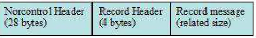
All messages are constructed into datagrams for transmission, and the datagram structure is shown in Figure 10 below.
Figure 10. datagram structure
When IHI sends multiple current vectors to the Polaris system, the datagram is constructed of multiple records. Based on the datagram structure in Figure 10, the datagram packet with multiple records starts with the Norcontrol header followed by the record header with its record message as the first record. The second record is
constructed after the first record with its record header and record message. Addition records can be added to the datagram packet until it reaches the maximum physical size of 1536 bytes.
Before IHI can send message data to the Polaris system, it is required to send a CMS active message to Polaris to enable it to receive external messages. Table 5 shows the format of the CMS Active record.
Table 5. CMS Active record
Type Name Description
RecHdr Record header Record ID 3022
uint16 Active 1 = Active, 0 = Inactive
Due to the characteristic of the UDP protocol, the data may loss during transmission via the Internet. Thus, this message should be sent more than one times to ensure the
message successfully activate the Polaris system.
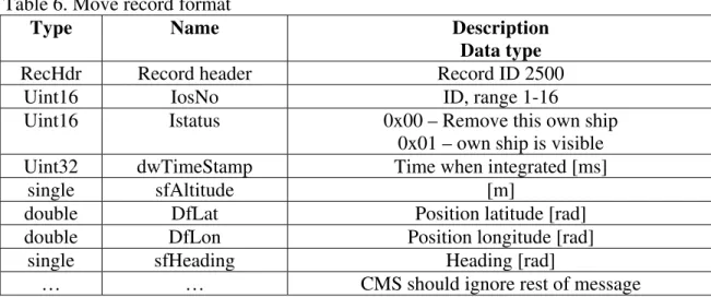
The Own Ships message is sent by Polaris to inform IHI about the own ships positions and size. Two records are used in the communication, the Move and the Hull records. The Move record has a port offset of 50 and a command number of 2500. The Move record is the first record in this Own Ships message. This single message contains information about a particular own ship. The IHI module is able to generate the hull geometry by itself during its self-initialization process; therefore, it only needs to capture the Move record for the ship motion information. Table 6 shows the format of the Move record.
Table 6. Move record format
Type Name Description
Data type
RecHdr Record header Record ID 2500
Uint16 IosNo ID, range 1-16
Uint16 Istatus 0x00 – Remove this own ship 0x01 – own ship is visible Uint32 dwTimeStamp Time when integrated [ms]
single sfAltitude [m]
double DfLat Position latitude [rad]
double DfLon Position longitude [rad]
single sfHeading Heading [rad]
… … CMS should ignore rest of message
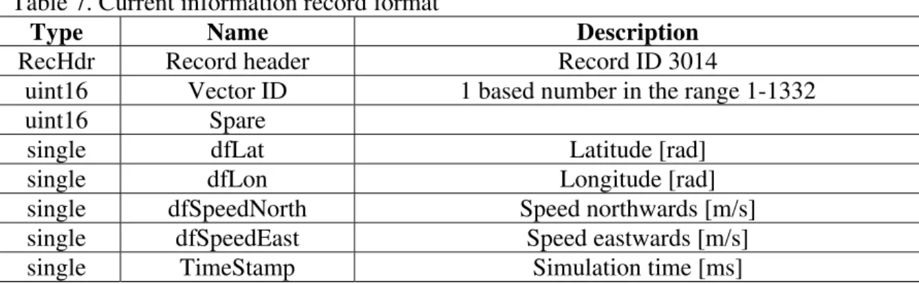
Subsequent to the ice force calculations and force-current conversion, IHI sends the current vectors information back to Polaris. Although the maximum number of current vectors that can be sent is 1332, only 52 current vectors can be packed and sent at one time due to the maximum physical size restriction for a message. The current vector records should be sent as part of the area message (see Table 2). Port offset for the area message is 40 and the associated command number is 3000. Each record contains the position and velocity of one current vector, and the message could be constructed with multiple vectors.
Table 7 shows the format of the Current information record. Latitude and longitude are sent with float32 instead of float64 to save some message size. The precision for latitude and longitude with float32 is about 1 meter that is good enough for the current vector; however, in order to declare the type in MATLAB environment, it has to be defined as single (float32) or double (float64).
Table 7. Current information record format
Type Name Description
RecHdr Record header Record ID 3014
uint16 Vector ID 1 based number in the range 1-1332 uint16 Spare
single dfLat Latitude [rad]
single dfLon Longitude [rad]
single dfSpeedNorth Speed northwards [m/s] single dfSpeedEast Speed eastwards [m/s] single TimeStamp Simulation time [ms]
5.0 CONCLUSION
The Bridge version of the IHI module and its integration into the Polaris system are completed. The final integration test of the IHI module and the Polaris system is successful. With different ship models, preliminary assessment demonstrated that IHI module successfully receives broadcasting from the Polaris simulator and sends current update back to it. The IHI bridge version is designed in MATLAB environment. It
provides standard UDP protocol to set up the communication interface in between the IHI module and the Polaris system.
6.0 REFERENCES
Centre for Marine Simulation, 2009. “UDF Polaris CMS Interconnection”, CMS document, St. John's, Newfoundland.
Zhang, E.Z. and Lau, M. 2009. “Preliminary Communication Protocol Assessment and Interface Development for IHI - Polaris Integration”, IOT report SR-2009-15, Institute for Ocean Technology, National Research Council of Canada, St. John's, Newfoundland.
JavaTM, Java TM Platform web source, Standard Edition 6, API Specification, http://java.sun.com/javase/6/docs/api/
Leon-Garcia, A. and Widjaja, I, 2003. Communication Networks, Fundamental
Concepts and Key Architectures, second edition, McGraw-Hill Companies, New York,
NY.
Ni, S.Y. and Lau, M., 2009. “Status Report of IHI Bridge Version for Integration with Polaris December 18, 2009 Contract Reference: #718855” Status report to the Center of marine Simulation from Institute for Ocean Technology, National Research Council of Canada, St. John’s, Newfoundland.
Appendix A THE USER MANUAL
The latest IHI bridge version is located in the directory
"IHI-OSIS UDP Dec.14\IHI_OPTION_1". The m-file client_ihi.m is the main function of the IHI module. All IHI computation routines are located in the IHI_Module folder, and the communication interface files are located in the Comm_Client folder. Both folders are linked to the client_ihi.m as shown in the following figure.
Comm_Client IHI_Module client_ihi.m
IHI_ownship_get.m client_ current_send.m
To start the IHI application, the user needs to enter the Polaris IP address, base port number, current value scale, and the ship name. The following figure gives an example of the process.
To set up the communication, the program displays the default IP addresses for both the listening and sending and an input request will pop up to let the user input the server’s IP address. If the default IP address is not correct, the user can manually input the new IP address. After the user confirms the IP address, the program will let the user to set the base port. Currently, for the IHI-Polaris application, the base port could be detected with application designed by Wayne Pearson. Then, the user can enter the current vector calibration factor that scales the current vector values before sending them to Polaris. This calibration factor (i.e., the current_scale) is implement to better match the IHI current model to its counterpart in the Polaris (Ni and Lau, 2009). Finally, the user is asked to select the initialization file that contains information on ship geometry and ice properties for the exercise, and the program starts running.
Function client_ihi()
This is the main communication routine for the IHI module. When the Polaris starts simulation, it will wait for the connection request from the IHI. The users need to start the IHI application on a separate computer. If the connection performed successfully, IHI computation will start. IHI fetches the ship motion data from Polaris by calling the function IHI_ownship_get(), and then activates the Polaris system to accept the external data. Then, IHI module starts the ice force computation to generate the global ice force and the individual ice force acting at each point defining the hull’s waterline profile. Each individual ice force is then converted to equivalent current data and sent back to the Polaris as current record using the function client_current_send().
Function IHI_ownship_get()
This function is called at the start of the main while loop of the client_ihi() function. The Move record of the own ship message is the data that IHI receives from Polaris system. This function is in charge of looking for the correct Move record and decoding them into MATLAB application data. If the received data do not match the requirement of the Move record format, the function will discard the data and keep checking for the next one. The input and output of this function are given as follows:
Input: the UDP object, udpIHI
Output: latitude, longitude, ship heading, and time stamp
At the beginning of the function, it flushes the input buffer in order to ensure the
datagram packet received is the latest one. This function will check whether the Internet packets received meet the requirement of the IHI module. If any correct datagram packet was detected, the data is recorded and decoded from binary number to numerical number. According to the data format of the Move record, the function is able to separate the packed data into different variables.
If no matching data comes from the Internet, the IHI program will be held in hibernate status, and waits for the incoming data to activate the program moving to the next step.
Function client_current_send()
This function is called after the IHI module finishes the ice force calculation, and converting the ice force into current with a format understood by the Polaris. This
function converts the current information into bytes array prior to sending them to Polaris. It also constructs the bytes array to match the datagram structures that Polaris
interconnection can accept. Finally, it sends the datagram packet to Polaris by UDP protocol. The input and exit of this function are given as follows:
Input: index number, UDP object udpSend, latitude, longitude, current speed of north, current speed of east, and time stamp
Return: to the main function client_ihi()
Before the IHI module can send data to Polaris, an active message has to be sent to enable Polaris to receive external messages. The index number passes in the current time step, if it is the first time step, the active message will be sent. All input data are in the format of numerical number, which need to be converted into a bytes array. The bytes array is constructed based on the format of current information message record discussed in Section 4.3.
At start of the function, it detects the input values in order to figure out how many current vectors will be constructed for the message packet. The maximum number of current vector that one message can accommodate is 53.
Trouble shooting issues
(1). The latest IHI bridge version is located in the directory
"IHI-OSIS UDP Dec.14\IHI_OPTION_1 " that has been compiled as an executable that does not need MATLAB environment to run the program. Double click the client_ihi.exe activates the IHI module that includes the communication functions and computation functions. It is important to compile the files before bringing it to CMS to run with the Polaris system. Both IOT and CMS do not have an individual licence for the Instrument Control Toolbox, only the network licence is available, therefore the IHI module can not be run or modified outside the IOT network. In order to test with the Polaris system at CMS, the code has to be compiled using the MATLAB compiler. (The procedure is shown in Appendix B).
(2). A laptop is required to do the integration test with the Polaris system in CMS. Laptop is available from the IOT HELPDESK group. All files should be stored in the C:\ drive of the laptop, and then log in as the user name of "IOTuser".
Before starting the IHI module, some network settings need to be done. Since IOT currently using the Windows XP operating system, the step-by-step instruction is showing below based on Windows XP OS.
1, Go to Start and click on Control Panel
2, Control Panel window will appear. Double click on Network Connections
3, Network Connections window will appear. Right click correct Local Area Connection by identifying correct network card and click Properties.
4, Select Internet Protocol(TCP/IP). Click on Properties.
5, Choose Use the following IP address and input the IP address. Input the IP address that the Polaris network is currently using. NOTE:
(3). If the IHI module is terminated by the user (such as Ctrl+C, or close the window) or error report, the UDP object would not be cleared and deleted correctly. The user has to manually delete the UDP object, otherwise the program cannot run again properly. To delete the object, type the following code in MATLAB’s command window. (The compiled version do not need this process.)
Obj=instrfindall Delete(Obj)
Or
Appendix B MATLAB’S COMPILER DIRECTION
MATLAB Compiler lets you run your MATLAB application outside the MATLAB environment. This architecture significantly reduces application development time by eliminating the need to manually translate your code into a different language. If you are building a standalone application, MATLAB Compiler produces an executable for your end users. If you need to integrate into C or C++, MATLAB Compiler provides an interface to use your code as a shared library.
Before You Start
Before you can use the MATLAB Compiler product, you must have it installed and configured properly on your system. Refer to Installation and Configuration of Matlab product documentation for more information. Run the following command at least once after installing a new version of the MATLAB Compiler product:
mbuild -setup
Then select the local compiler and confirm your selection. If you need information about writing the M-files that you plan to compile, see MATLAB Programming, which is part of the MATLAB product documentation.
Example of Compile the IHI application
If we want to compile the IHI module, select the corresponding directory as your MATLAB working directory, i.e., C:\IHI_OSIS UDP\IHI_OPTION_1. This will
show all files and folders located in the IHI_OPTION_1 directory as shown in the above diagram. In the command window, you need to type in the following command: mcc –m client_ihi.m –a ./Comm_Client/*.m -a ./IHI_Module/*.m
The client_ihi.m is the main function of the IHI application, it is stored under the directory IHI_OPTION_1. You need to store all other files of the IHI application in a sub-folder. In this example, the folder “IHI_Module” includes all the IHI computation functions. All files with the extension .m within the ./IHI_Module subdirectories are added to the CTF archive, and the subdirectories of ./IHI_Module are not processed recursively. Hence, the option –a ./IHI_Module/*.m adds the path of all m-file under the "IHI_Module" folder.
Perform the same operation for the folder "Comm_Client", which includes all the
communication function files. By executing the above command, the client application is compiled after Matlab finishes its process. It will generate a client_ihi.exe file in the same directory. This exe file can be run as a stand-alone application.
Note: For the folders that contain the m-files to be compiled, the folder name cannot have any space, such as "IHI MODULE". It has to be changed to a name without any space, such as "IHI_Module" or "IHIModule"
Example of P-code
When running a m-file in MATLAB, the m-file will be convert to p-file. It could increase the running speed if all m-files have already compiled to p-files. Furthermore, if all the related m-files are converted to p-file, the program is able to run correctly with all the related p-files. The p-file cannot be viewed or edited by common users. If we do not want users to touch our source code, convert all the m-file to p-file will help.
Select the target folder in MATLAB directory, then in the command window type: pcode *.m. Keep doing that for all related folders. At the end of conversion, delete all the m-files.
Note:
1. Make sure backup your files before doing it.
2. If p-files already exist in your program folder, anytime after any change of your code, make sure you pcode your program again, otherwise, MATLAB will keep running the old p-files. Or, you may delete all your p-files to ignore the issue.